General structure and operation of the KAMAZ cab tilting mechanism
The cabover layout inherent in Kama trucks makes it difficult to some extent to carry out maintenance and repair work on units located under the cab. Therefore, these trucks use a tilting cab and a special autonomous system - a cab tilting mechanism, or MOC. On some truck models, this system is also used to raise and lower the spare tire mounted behind the cab.
The IOC includes a small number of components:
- Manual hydraulic pump;
- Oil tank (in modern truck models, the tank is combined with a pump, since the system uses a small amount of oil);
- Double acting hydraulic power cylinder;
- A system of piping for supplying oil from the pump to the cylinder (usually metal tubes).
The cab tilting mechanism functions simply: using a pump, hydraulic oil is pumped into a power cylinder, the rod of which comes out and raises the cab to one or another angle (41° or 61°). The return of the cabin to the horizontal (transport) position is also carried out by means of the MOC; in this case, a special handle on the pump is moved to another position, as a result, the oil flow is reversed, and the power cylinder rod is retracted, lowering the cabin. Manipulations with the spare wheel are carried out in a similar way; for this, the pump spool (using the handle) is moved to the appropriate position.
The components of the mechanism are located on the frame side member (in early truck models, parts were most often located on the right side member; in many current models, parts are located on the left side member): the hydraulic cylinder is in the front part, directly under the cab, the pump is above or immediately behind the rear cab suspension, which provides free access to this unit. Metal oil pipes are laid along the frame between the pump and the power cylinder.
The MOC system may include a separate control valve located behind the pump on a special bracket. However, this solution was used on early KAMAZ trucks, but today all controls are located directly on the pump.
To ensure smooth tilting of the cabin and reduce the load on the IOC, an additional balancing mechanism is used. It consists of two torsion bars twisted in different directions, which are connected to the cabin and frame side members. When the cabin is raised, one torsion bar is twisted and the other is untwisted, which ensures the equilibrium position of the cabin at all angles of its elevation.
The main part of the IOC is the pump; we should dwell on it in more detail.
Cabin. Part 1
Section 7. CABIN
Kamaz 4308 vehicles have a three-seater cabin without a berth.
The cabin has a sprung suspension, providing reliable insulation from the influence of the road. To service the engine, the cabin tilts forward. In the operating position, the cabin is held in place by two lever-type locking devices.
The cabin doors are equipped with roll-down windows and rotating windows. The windshield glass is safety glass, triplex type. The device for cleaning and washing windshields is electrically driven and consists of an electric motor with a gearbox, rods and brushes, a reservoir with an electric pump located in the cabin under the instrument panel, tubes, jets and control keys.
Natural ventilation carried out through windows and door vents, a ventilation hatch in the roof, as well as a heating system powered by an engine cooling system with forced air supply, to the feet of the driver, passengers, windshields and door windows, allow you to set the optimal temperature in the cabin in any time of year and protect glass from freezing.
The cabin is equipped with reliable multi-layer thermal and noise insulation and soft upholstery. The driver's seat is adjustable, which provides optimal working conditions for the driver. The cabin has seat belts for all three seats in the cabin.
Special aerodynamic devices: side fairings, roof fairings, the installation of which is provided on cabs, reduce the aerodynamic resistance to movement of the KamAZ 4308 vehicle, increase fuel efficiency, and reduce pollution of the KamAZ 4308 vehicle when driving on wet roads.
The cab of the KamAZ 4308 vehicle consists of the following main parts: body, doors, glazing, seats, thermal and noise insulation and interior parts, equipment, as well as tail parts (wings, running boards, facing panel, etc.) and cab mounting parts.
| Cabin specifications | |
| Cabin weight, three-seater, without sleeper, kg: | 550 |
| Overall dimensions of the cabin, mm: | |
| - length (along the wings) - width (along the wings) | 1890 2482 |
| - internal width at shoulder level | 2040 |
| — height (with wings) | 2040 |
| Cabin tilt angles, degrees: | — |
| — allowed by the limiter | 41 |
| — maximum when removing the engine* | 61 |
| Angle of rotation of windshield wipers from horizontal, degrees: | 8-98 |
| Wiper speed, double strokes per minute | 30, 70 |
| Pressing force of the windshield wiper blade to the glass, N (kgf) | 3,43-3,92 (0,35-0,4) |
| Windshield washing | from an electric centrifugal pump built into the tank |
| Windshield washer reservoir capacity, l | 2 |
| Angle of inclination of the driver's seat back from the vertical, degrees. | 9…19 |
| Longitudinal travel of the driver's seat, mm | 135 |
| Angle of inclination of the right passenger seat back from the vertical, degrees. | 12 |
| Seat belts: | — |
| driver | diagonal-waist RB 3-44 |
| average passenger | diagonal-waist RB 3-45 |
| last passenger | belt RB ZS-45 |
| Rear view mirrors | flat or spherical, with two degrees of freedom, mounted on the outer panel of the door |
| * To tilt the cab at 61°, first remove the buffer (or headlights) and lift the trim panel. | |
Cabin body
The cabin body is the power part of the cabin and the basis for fastening all components and equipment.
The cabin body is all-metal, assembled by spot welding from stamped panels, pre-assembled into assembly units: base, front, two side panels, rear and roof. Moreover, cabins without a berth and with a berth are maximally unified with each other. For cabins with one and two berths, only the roof differs and sidewall extensions and a middle rear panel (the berth itself) are added. All cabin panels are made of thin sheet steel with a thickness of 0.9 to 1.2 mm. The rigidity of the panels is provided by the ribs stamped into the panels and the panel frames.
At the junction of the panels, complex closed sections of the beams of the cabin frame are formed, which, together with the frames of the panels themselves and the panels, create the power structure of the cabin and provide high rigidity and strength of the cabin.
Cabin mounting
The cab is attached to the frame at four points using two front hinge supports and two rear sprung supports with a locking mechanism.
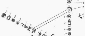
The front hinge supports (Fig. 7-1) consist of lower brackets 1, bolted to the first frame cross member, and upper brackets 5, which are attached to the floor cross member. The articulated connection between them allows the cabin to be tilted forward.
To soften vibrations transmitted from the frame to the cab through the front supports, rubber cushions are built into the upper brackets. The torsion bars 12 of the cab balancing mechanism are fixed in the lower brackets of the front cab mounting.
The rear mounting of the cab (Fig. 7-2) is combined with a soft cab suspension and consists of two longitudinal leaf springs 1, which are attached to brackets 13, rigidly mounted on the frame spar 14, and two hydraulic telescopic shock absorbers 11, which are fixed to the bracket with the lower eye , and the upper eye is in the spring cage 9. Bracket 6 of the locking mechanism is attached to the spring cage, to which the locking device attracts the cabin. The downward movement of the cabin is limited by a rubber buffer, which is built into the shock absorber.
The shock absorber of the cab suspension mechanism is similar in design to the shock absorbers of the front suspension of the Kamaz 4308 car. At a piston speed of 0.25 m/s, control data for the shock absorber resistance forces during the compression stroke are 94.2...259 N (9.6...26.4 kgf), during the stroke rebound - 895-1271 N (91.2-129.6 kgf).
The cab tilting mechanism (Fig. 7-3) serves to facilitate tilting the cab forward when servicing the engine and should ensure almost complete balancing of the cab in any inclined position.
The cabin tilting mechanism consists of two interchangeable torsion bars 12 (Fig. 7-1), which are fixed with square ends in the lower brackets 1 of the front supports, and with splined ends are loosely installed in rubber bushings 13 of opposite brackets. At the splined ends, interchangeable levers 7 torsion bars are secured with coupling bolts 2, whose upper ends rest against the bushings 9 of the supports 8 torsion bars.
The torsion bars in the transport position of the cab are twisted at an angle of 53°.
The cabin tilts 41° and, if necessary (to remove the engine), can tilt 61°. To do this, release the extension of the cab lift limiter.
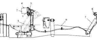
Kamaz-4308 vehicles have a mechanism for raising and lowering the cab (Fig. 7-3) with hydraulic drive and manual control. The mechanism consists of a hand pump, a cylinder for raising and lowering the cabin, and oil supply pipes connecting the pump and the cylinder. A mounting blade for tires or a wrench for a wheel wrench is used as a handle for the pump drive shaft.
Rice. 7-1. Front fastening and cockpit balancing mechanism: 1 — lower bracket; 2 — coupling bolt: 3 — lock washer; 4 — finger (axis); 5 — upper bracket; 6 — front floor beam; 7 — torsion bar lever; 8 — torsion bar lever support; 9 — support bushing; 10 - floor reinforcement; 11 — cross member of the first frame; 12 — torsion bar; 13 — torsion bar bushing; 14 - plate; 15 - insert of the floor cross beam.
Rice. 7-2. Rear cab support: 1 — leaf spring; 2 - bolt; 3 — spring pad; 4 — spring stepladder; 5 — spring clamp; 6 — locking bracket; 7 — rubber cushion; 8 — locking bracket; 9 — clip; 10 — rubber buffer; 11 — shock absorber; 12 — shock absorber bracket; 13 — bracket; 14 — frame spar.
Rice. 7-3. Mechanism for raising and lowering the cabin: 1 — cabin tilting pump; 2 — cabin lowering tube; 3 — cabin lift tube; 4 — right frame spar; 5 - hydraulic cylinder.
The cabin lifting and lowering pump (manual, plunger type, single-acting) is attached to the right side member of the vehicle frame.
The maximum pressure developed by the pump is 18 MPa (180 kgf/cm2).
The pump is controlled by setting the spool in one of two positions - LIFTING - LOWERING. The spool is installed using a handle.
The drive shaft has a hole with a diameter of 20 mm for the mounting blade or wrench included in the tool kit for the car. The force on the handle at a distance of 600 mm from the longitudinal axis of the drive shaft at a pressure of 20 MPa (200 kgf/cm2) should be no more than 38 kgf.
The level of working fluid in the pump (cabin in transport position) is limited by the lower edge of the filler neck. MGE-10A oil is used as the working fluid.
Rice. 7-5. Cylinder for raising and lowering the cabin: 1 — rod wiper; 2, 7 — cuffs; 3 - plug; 4 — cylinder glass; 5 - rod; 6 — rod half-rings; 8 — washer; 9 - nut; 10 — traffic jam; 11 - pin; 12, 14 — sealing rings; 13 — bushings of cuffs; 15 — cylinder cover; 16 — cover nut.
The cabin raising and lowering cylinder (Fig. 7-5) is equipped with safety valves (Fig. 7-6). On the cabin lifting and lowering cylinder, the valves are installed on the outlet holes, closed with plugs.
Rice. 7-6. Safety valve: 1 - body; 2 - spring; 3 - ball; 4 - plug.
Safety valves, which are check throttle valves, close when a hose ruptures or other damage to the system causes the car to drop quickly and stops lowering the car. The valves can also close if the oil supply is too sudden; in this case, to open the valve, the spool handle must be turned to the position opposite to the operation being performed (if the cabin was lowered, then set the handle to the lifting position, and then to the previous position and continue lowering).
Raising the cabin. Before lifting the cab, it is necessary to brake the KamAZ 4308 vehicle with the parking brake system and set the gear shift lever to the neutral position. Then you need to turn the handles of both cab locks to the uppermost position and disengage the safety hook of the right lock.
To raise the cabin to the first position (at an angle of 41°), set the spool handle on the pump to the “Lift” position and, shaking the drive shaft with a mounting blade, raise the cabin. To prevent accidental lowering of the cab, it is necessary to secure the limiter posts with safety pin 8 (Fig. 7-7).
To lower the cabin, remove the locking (safety) pin, set handle 6 on the pump to the “Lowering” position and, pumping drive shaft 2 with a mounting blade, lower the cabin.
To raise the cabin to the second position (at an angle of 61°), it is necessary to remove the front buffer, lift the front facing panel and raise the cabin to the first position; Unscrew and remove pin 2 of the extension. Then, pumping the pump drive shaft with a mounting blade, raise the cabin to the second position.
The cab lift limiter is located on the right side of the cab. The lower post 7 (Fig. 7-7) of the limiter rotates in the lower bracket 6, mounted on the right side member of the frame. The upper rack 9 is attached through an extension to the upper bracket 3, fixed to the longitudinal beam 1 of the cabin floor. When the cab is raised, both pillars create a stop that prevents the cab from spontaneously lowering. To prevent accidental folding of the limiter, there is a safety pin 8 between the lower and upper posts.
Rice. 7-7. Cabin lift limiter: 1 — cabin longitudinal beam; 2 — extension finger; 3 — upper bracket; 4 - hydraulic cylinder; 5 — hydraulic drive; 6 — bottom bracket; 7 — lower stop of the limiter; 8 — safety pin; 9 — upper stop of the limiter.
Possible malfunctions of the cab raising and lowering system and ways to eliminate them
| Cause of malfunction | Remedy |
| Stiff swinging of the pump handle or complete jamming of the injection plunger. System operation does not correspond to the position of the control levers | |
| Incorrect connection of hose tips or incorrect installation of pump spools in their sockets | Inspect the system, rearrange the hose tips correctly. Check and, if necessary, sort out the spool assemblies |
| Clogged nozzle or filter | Clean and rinse the filter and nozzle |
| Water entering the working fluid and the formation of ice plugs, use of non-recommended oil in the system | If there is ice, warm up and clean the pump, rinse with fresh oil, change the oil in the pump. Remove oil from the entire system, refill the system with the recommended oil |
| While raising or lowering the cab or the spare wheel, the system is jammed (usually after a sharp pump swing of the handle) | |
| The safety valve is closed and does not open | Turn the reversing spool handle to the position opposite to the operation being performed, and then to the desired position and continue the operation |
| The pump works (there is supply), but the cabin does not rise (does not lower) | |
| Pump safety valve malfunction (does not provide required pressure) | Remove the valve, preventing oil from pouring out of the cylinder or hose, disassemble, clean, wash, adjust to the required pressure of 15-17 MPa (150-170 kgf/cm2). Valve filters can be removed without replacing them |
| The pump does not work (no flow), pump parts move without jamming | |
| Malfunction of the pump suction valve (does not close at all or does not close tightly) | Unscrew plug 3 (Fig. 243), remove spring 2 and suction valve ball. Inspect the parts and valve seat (inside the body). Eliminate the cause of the problem |
| Oil leakage at the joints of the fuel pipes, from under the elbows and the suction valve plug | |
| Leaks, wear or damage to sealing parts, worn threads | Tighten the leaking connection, check the sealing parts, replace if necessary |
The cab locking mechanism (Fig. 7-8) fixes the cab on the rear supports in the transport position and consists of two mechanical locks with a safety hook on the right locking device.
The lock housing 6 is attached to the rear beam and the longitudinal beam of the cabin floor. The lock handle 11 rotates on the axis 9 of the lock. Hook 10 rotates on pin 8 of the axis. When fixing the cabin, the body with its groove fits into bracket 12, welded to bracket 14, fixed to the spring cage, and hook 10 engages with the bracket. The design of the hook ensures that when closing the lock, the body 6 of the lock is pulled towards the rubber cushion 13 on the bracket bracket. The safety hook 5 is automatically snapped into the bracket using a spring 4.
To open the lock before tilting the cab, turn the handles of both locks from the lower position towards you, to the upper position, while the hook disengages from the bracket, then disengage the safety hook.
Rice. 7-8. Cabin locking device: 1 — safety hook bracket; 2 — cabin lock body; 3 — handle of the locking handle; 4 - spring; 5 — safety hook; 6 — lock body; 8 - finger; 9 — constipation axis; 10 - hook; 11 — locking handle; 12 — bracket; 13 — rubber cushion; 14 — bracket.
Cabin doors
The cab doors open forward, are suspended from the A-pillar, and are locked with a lock at the rear. The door consists of outer and inner panels, which are spot welded along the perimeter and along the window contour.
At the bottom of the interior panel there is a hatch for draining water from the door, closed with a polyethylene plug. In the middle part of the inner panel there are two hatches intended for installation and dismantling of the window regulator, glass and door lock, covered with a plastic panel. Attached to the bottom of the inner door panel is a plastic pocket for small items.
The door seal consists of two seals. The first is a door seal made of sponge rubber, glued to the inner door panel along the entire perimeter. With its petal it presses against the side when closing the door. The second is the door opening seal, made of an elastic rubber-metal profile that fits onto the door flange, which, with its spongy part, made in the shape of a tube, is pressed against the inner panel of the door.
The door is suspended from the front pillar of the cab on two hinges. Each hinge consists of two-ear and three-ear loops connected by an axis. The two-ear hinge is welded to the inner panel of the door, and the three-ear hinge is attached with four bolts to the front pillar of the cab, inside of which there are special floating plates that allow adjustment of the door hinge. Limits the door when opening and locks it in the open position with a door stop, which is an arched lever hinged on the inner panel of the door, with a rubber buffer and leaf springs at the other end, which engage with the latch when the door is fully opened.
The door locking device consists of a door lock, a lock retainer, an internal drive with a handle and an external handle with a handle lock button. A rotary-type door lock (Fig. 7-9) with a safety lock and a push-button drive is attached to the end of the door with three screws. When you press the button on the outside door handle, the button rod presses the latch flag 4, which, turning, disengages from the ratchet 2, which leads to the rotation of the rotor 5 and the opening of the door.
Rice. 7-9. Rotary door lock: 1 - springs; 2 - ratchet; 3 - latch; 4 — latch flag; 5 - rotor; 6 — traction lever; 7 - traction.
The inner door handle is connected to the lock using a drive and rod 7. The drive housing is attached to the inner door panel with three screws. When turning towards you (upwards) the inner handle, sitting on the splines of the drive arm axis, the latter, turning and compressing the springs 1, through the drive rod 7, turns the lock rod lever 6, which, in turn, turns the latch 3, ratchet 2, rotor 5 castle When you turn the inner door handle away from you (down), the locking spring enters the recess of the lock rod lever and fixes this position of the latch.
Now, when you press the outside handle button, the lock will not open. When opening the doors from the inside, the lock is released from the safety lock by turning the inside handle toward you.
The door is locked from the outside using a lock built into the button on the outside door handle. When turning the key (locking), the locking plate of the button with its protrusions fits into the grooves of the handle and does not allow the button to move. The door can be opened from the inside.
When the door is closed, the lock rotor turns and enters the latch, which is attached to the rear side pillar with four screws. A tight fit of the door to the opening is ensured by two ratchet positions; in intermediate and fully closed positions.
The door windows include roll-down glass and rotary windows, which are separated by fixed pillars. Door glass is tempered and polished. Heat treatment ensures the strength of the glass, and upon impact, the glass breaks into small blunt fragments. Rolling down door windows move up and down along guides in which rubber seals are installed.
The lower end of the glass, being the supporting one, is pressed into a holder with a rubber gasket. The window lifter link is welded to the frame in the middle.
The rotary window in the opening rotates on two axes. The lower axis and the socket of the upper axis of the window are welded to the glass through a special film using high-frequency currents. The window lock handle is also welded to the glass. The window opens by turning the handle 90°, and the tongue of the handle disengages from the locking cylinder.
The door window window regulator (Fig. 7-10) is cable driven and is attached to the inner door panel with six screws. The mechanisms of the right and left window lifters are interchangeable.
When the window lifter handle rotates, the force through the drive roller 2 is transmitted to the drive gear, which rotates the drum 1 with the cable 3 wound on it. The movement of the cable causes the movement of the sliding window clip, attached to the vertical branch of the cable.
The drive has a large gear ratio (nine to ten turns of the handle to move the glass in one direction), so the ease of moving the glass is ensured. The force on the window lifter handle is approximately three times less than the weight of the glass. The glass is fixed in any position by a brake mechanism mounted on the drive roller. The brake mechanism can withstand a load of up to 75 kg applied to the glass in the vertical direction.
Wind and rear cab windows
The cockpit wind window consists of a V-shaped glass arrangement. The windshield glass is flat, three-layer, triplex type (two polished glasses with a transparent, colorless plastic film between them). The use of such glass increases safety for the driver and passengers, since upon impact the glass cracks, but the fragments do not separate from the plastic film.
Rice. 7-10. Cable window lifter: 1 — drum; 2 — drive roller; 3 - cable.
The windshield glass is reinforced along the window opening with a special rubber seal. The cross-section and hardness of the seal are selected in such a way that reliable fastening of the glass and tightness of the connection are ensured. The seal fits tightly to the glass and the opening along the entire contour and does not allow water to pass through. In addition, for better sealing, the sealing points with the glass and with the wind window opening along the entire contour (or in the lower half of the contour) are coated with sealing paste.
The lock and the edge of the seal protect the glass from falling out of the seal. The two rear cab windows have tempered polished glass.
Rice. 7-11. Device for cleaning and washing windshields: 1 - gear motor; 2 - jet; 3 - pump; 4 — washer reservoir; 5 — brush lever; 6 - transmission unit.
The device for cleaning and washing windshields (Fig. 7-11) includes an electric wiper and washer. The windshield wiper and washer are controlled by the right lever of the combination switch (Fig. 4) and the windshield wiper relay. To activate windshield washer pump 2, lift the windshield wiper switch lever up and hold it in this position for no more than 10 s. In this case, liquid from tank 4 is supplied to jets 2, through which it is sprayed onto the windshields. After lowering, the lever returns to its original position.
To turn on the windshield wiper, move the windshield wiper switch lever to one of the fixed positions. In the first position of the switch lever, gear motor 1 provides 20...45 double strokes of the levers with brushes per minute, in the second position - at least 45 with a difference between the first and second speeds of at least 15 double strokes per minute, in the third - intermittent operation of the windshield wiper.
In the off position of the switch, the brushes are automatically placed in their original position.
Cabin ventilation and heating
The ventilation of the cab is natural, carried out by using the counter flow of air when the KamAZ 4308 vehicle is moving. For ventilation, you can use the rotating windows and roll-down windows of the cab doors, and there is also a special ventilation hatch in the roof.
The roof ventilation hatch (Fig. 7-13) can have four fixed positions, creating either forced or ejection ventilation.
Cabin heating (Fig. 7-12) is water, from the engine cooling system, with forced air supply to the windshields, door windows, legs and face of the driver and passengers. Heater radiator 8 is placed in a niche in the front panel on the outside of the cabin, and two fans with air distributors are placed on the front panel on the inside and covered with a plastic casing.
The heater radiator is included in the engine cooling system. Hot liquid enters the heater radiator from the cylinder head through supply pipes and hoses 11, 16, 17 through heater valve 10, located on the front panel next to the radiator. Through the supply hose 11, the liquid enters the lower part of the radiator, and through the drain hose 12 from the upper part of the radiator it enters the suction cavity of the water pump. Heater valve 10 regulates the amount of liquid entering the radiator from the engine cooling system and is activated by a flexible cable from the upper lever on the drive panel under the instrument panel to the left of the driver. When the lever is in the extreme left position, the tap is completely closed. Liquid from the engine cooling system does not flow into the heater radiator - the heating is turned off. By moving the lever to the extreme right position, we gradually increase the amount of liquid supplied to the radiator, thereby increasing the heating intensity.
It is impossible to completely turn off the heater valve at negative ambient temperatures in winter to avoid freezing of the radiator, and at lower temperatures it is recommended to open the heater valve completely.
The efficiency of the heater depends on the temperature of the coolant in the engine cooling system. When the liquid temperature is below plus 75 °C, the heater efficiency drops sharply.
Outside air through the grille of the facing panel enters the radiator 8 of the heater, is heated and supplied by fans through the air distributor through hoses 4, 5 to the windshield blower nozzles 3, to the rotating air distributors 1 on the instrument panel and, with the distributor flap raised, to the feet of the driver and passengers. The air ducts on the instrument panel can be rotated horizontally by 360°, allowing air to be directed to the door windows, the driver and passengers, or additionally to the windshield.
The air distributor flaps are actuated by flexible rods from two lower levers on the drive panel to the left of the driver. The lower lever controls the left air distributor, the upper - the right.
Rice. 7-12. Cabin heating and ventilation system: 1 — hot air distributor; 2 - heating control drive; 3 — windshield blower nozzle; 4 — side window blower hose; 5 — windshield blower hose; 6 — control cable for the left distributor flap; 7 — control cable for the right distributor flap; 8 — heater radiator; 9 — heater valve cable; 10 — heater valve; 11 — front heater supply hose; 12 — heater outlet hose; 13 — drain hose; 14 — engine radiator; 15 - drain valve; 16 — heater supply pipe; 17 — middle heater supply hose; 18 — water intake pipe; 19 — electric motors; 20 — ventilation hatch.
When the levers are in the extreme left position, the air diffuser flaps are raised, air is supplied to the windshields, deflectors and to the feet of the driver and passengers. When the levers are in the extreme right position, the flap closes the hole in the lower part of the air distributors and air flows only to the windshield blower nozzles and to the rotating deflectors on the instrument panel. Intermediate positions of the levers can achieve optimal distribution of air flows throughout the cabin. The power of the air flow entering the cabin through the radiator can be adjusted by changing the speed of the electric motors of the 19 heater fans. Electric motors 19 are controlled by the upper left button on the switch panel of the instrument panel. The button has three fixed positions; fans are off, first speed and second speed of fan rotation. When the outside air temperature is down to minus 10 ° C, the counter pressure of air is sufficient to heat the cabin, and only at very low temperatures is it necessary to turn on the electric motors of the fans at maximum frequency (this ensures normal temperature conditions in the cabin and increases the service life of the electric motors). When operating a KamAZ 4308 vehicle in the summer, when the heater valve is turned off, you should block the air supply through the heater radiator into the cabin with the radiator cap.
Rice. 7-13. Roof ventilation hatch: 1 — ventilation hatch cover; 2 — lever spring; 3 — hatch cover lever; 4 — movable roller of the lever; 5 — lever stop; 6 — hatch lining; 7 — hatch handle; 8 — hatch cover bracket; 9 — visor of the ventilation hatch; 10 — hatch bracket; 11 — amplifier for the ventilation hatch; 12 — cabin cover. I — closed position of the hatch cover; II, III, IV - three open positions of the hatch cover.
Cabin seats
The driver's seat (Fig. 7-14) is single, with a torsion-type suspension mechanism and a hydraulic shock absorber, with adjustments for suspension stiffness, longitudinal movement and backrest angle. The driver's seat is suspended by a plate torsion bar installed in pipe 7. One end of the torsion bar is tightly fixed, the other is connected to the lever of the suspension stiffness adjustment mechanism.
When the adjustment handle 2 is rocked, either the torsion bar is twisted to increase the stiffness of the suspension, or, conversely, the torsion bar twist is reduced. To do this, after sitting on the seat, you need to pull handle 2 and turn it around its axis so that the “+” or “—” sign is visible, respectively. When driving on an uneven road, the vibrations of the seat are dampened by a hydraulic telescopic shock absorber 6, installed behind the back of the seat and fixed at one end to the base of the seat, and the other in the cross member of the seat frame. The shock absorber is of a monopipe design, gas-filled, non-removable. The downward sagging of the seat is limited by rubber buffers. Seat suspension travel is 88 mm. The suspension is designed for a driver weight of 491-1275 N (50-130 kgf).
The longitudinal movement of the driver's seat is carried out by moving the upper guides 17 together with the suspension mechanism and the seat along the lower guides 11 attached to the cabin floor. The seat position is fixed by a stopper 15, which holds the seat in one of ten fixed positions. When you press the stopper lever 16, it comes out of the corresponding groove of the comb 12 and releases the seat. The spring returns the stopper to the reverse position. Seat travel -135 mm.
The angle of the driver's seat backrest can be adjusted by choosing one of three fixed backrest positions: 9, 14 and 19° from the vertical. The position of the backrest is fixed by the tongues of the backrest brackets, which fit into the grooves of the combs on both sides of the backrest. When you press the comb lever 5, the backrest is released and fixed in the new position. The driver's seat cushion 1 and backrest 8 are made of latex rubber or molded polyurethane foam with a thickness of 50-70 mm, on a cup-shaped base made of sheet steel. The upholstery of the pillow and backrest is made in two versions: from embossed artificial leather or from fabric with cross stitching of the loaves. The upholstery is secured to the base flange with spring clips.
The driver's seat is installed in the holes of the cab floor and secured with bolts welded to the lower guides 11 and self-locking nuts on the outside of the cab.
Rice. 7-15. Passenger seat: 1 — back; 2 — side of the seat; 3 - pillow; 4 - tool box.
Rice. 7-14. Driver's seat: 1 - cushion; 2 — handle for adjusting the rigidity of the seat suspension; 3 - back; 4 — side of the seat; 5 — comb lever; 6 — shock absorber; 7 — torsion bar pipe; 8 — seat frame; 9,10 — suspension joint arms; 11 — lower guides; 12 - comb; 13 — return spring; 14 - thrust; 15 - stopper; 16 — stopper lever; 17 — upper guides; 18, 20 — crossbars of levers; 19 - base.
The middle passenger seat has no suspension and is not adjustable. The middle seat cushion (united with the driver's seat) is attached to a rigid stand, and the backrest, also unified with the driver's seat, folds forward to provide access to the berth. The backrest is held in the upper position by two coil springs. The seat is secured to the floor by four bolts welded to the base of the seat base.
The outboard passenger seat (Fig. 7-15) is mounted on the toolbox. To access the tool box, the backrest can be folded forward. Next, the backrest with a cushion reclines on hinges towards the driver.
Types, features and models of MOK pumps
On early and current models of Kama cars, only one type of MOK pump is used - manually driven plunger pumps. The choice of a hand pump was not made in vain - it ensures the operation of the system when the engine is stopped and in any conditions.
There are two large groups of pumps that differ in design and purpose - single-circuit and double-circuit.
Single-circuit pumps are most often used in IOC, but can also be installed on trucks with a hydraulic spare wheel lift - in this case, the system is equipped with an additional control valve (spool), through which the pump is connected either to the cab tilting hydraulic cylinder or to the spare wheel hydraulic lift.
Double-circuit pumps are used on vehicles with a hydraulic lift for a spare wheel installed behind the cab. The use of this type of pump makes an additional control valve unnecessary, as a result the entire system is simplified. Structurally, double-circuit pumps differ slightly from single-circuit pumps, as discussed below.
Currently, the Kama Automobile Plant uses MOK hydraulic pumps of two brands:
- BAGU - produced by OJSC Borisovsky, Borisov, Belarus;
- PPT - produced by the Prva Petoletka plant, Republic of Serbia.
Serbian and Belarusian pumps have some design differences and different characteristics, so in most cases they are not interchangeable.
Types and applicability of MOK hydraulic pumps
Today, manual plunger-type pumps are used in cab tilting mechanisms of Kama trucks (the same ones are used in hydraulic jacks). Regardless of the model, all plunger pumps are designed the same; the design of the pump is described below.
There are two main types of pumps used in Kama plant trucks:
• Cab tilting mechanism pump; • Cab tilt and spare wheel lift pump.
In the first case, the pump is designed most simply, and it is always connected only to the circuit of the cab tilting mechanism. The second type of pump provides the ability to switch between the MOC and spare wheel hydraulic lift circuits. That is, one pump can operate in two systems, which makes the car cheaper, and its maintenance and operation easier. Let us remind you that in a number of KAMAZ vehicle models (for example, KAMAZ-4310), the spare wheel is installed behind the cab on a special hydraulic lift - this facilitates the process of removing and storing the wheel, which has a fairly large mass and dimensions.
Currently, several models of pumps from two main manufacturers are installed on KAMAZ vehicles:
• Pumps Prva Petoletka (PPT), Serbia; • Pumps of JSC Borisovsky (BAGU), Republic of Belarus.
Pumps from different manufacturers have different characteristics, differ in installation dimensions and other parameters, which must be taken into account when purchasing a new pump.
But all pumps, regardless of model and applicability, have a fundamentally identical design.
Design and operation of MOK pumps
Structurally, all models of hydraulic pumps are not fundamentally different; the following parts can be distinguished:
- Plunger pair - pump section, which ensures oil injection into the system;
- The valve mechanism is a tube with two ball valves. The suction valve ball simply sits in its seat and can be easily lifted, the second valve is formed by a ball and a spring, it opens only when the required oil pressure is reached;
- The pump section (plunger) drive handle is a short handle, pivotally mounted on the pump housing cover, and connected to the plunger by a rod;
- The reversible spool is the main pump control element; it helps reverse the direction of oil flow from the pump section to the hydraulic cylinder. The spool is equipped with a handle that has two fixed positions - “Raise the cabin” and “Lower the cabin”. In the first position, oil from the pump is supplied under the cylinder piston, as a result of which it rises and tilts the cabin, at which time oil from the above-piston cavity returns to the tank. In the lowering position, oil from the pump is supplied to the above-piston cavity, and from the under-piston cavity it freely returns to the tank - the rod lowers and returns the cabin to a horizontal position;
- Oil tank - in PPT pumps, the oil tank is attached to the housing in which the plunger pair, spool and valves are located; in BAGU pumps, the functions of the tank are performed by the pump body itself, and the plunger pair and valves are always immersed in oil.
How to install a KAMAZ cab lift cylinder
KAMA3-4310 (43101).
REPLACING THE HYDRAULIC CYLINDER OF THE CAB LIFTING AND LOWERING MECHANISM The hydraulic cylinder must be replaced if the following malfunctions occur:
1. Cracks, breaks, cylinder dents, thread failure in threaded holes.
3. Oil leakage due to wear or damage to the rod seal lip.
Tools and accessories: keys 17X19, 22X24, screwdriver, pliers, hammer, spatula-wrench 594416, liquid containers, M18X 1.5 plugs, funnel with double mesh. Removing the hydraulic cylinder
1. Raise the cab to the first position and lock it
2. Unscrew the union nuts 2 (Fig. 66) and disconnect the hoses 1 from the cylinder 5. Install plugs in the hoses
3. Unpin and remove pin 6 securing the cylinder to bracket 7 of the cabin
4. Take out the cotter pin and remove cylinder 5 from frame bracket pin 4
5. Place the cylinder 5 with the eye on the bracket pin 4 and pin it
6. Install the cylinder into the eyes of bracket 7, insert pin 6 and pin
7. Connect hoses 1 to cylinder 5, screw and tighten nuts 2
8. Fill the reservoir of the cabin lifting and lowering pump with MGE-10A hydraulic fluid to the lower edge of the filler neck and pump the hydraulic system of the cabin raising and lowering mechanism in the following order:
— set the handles of the cabin raising and lowering pump to the position
pump oil into the cylinder cavity by pumping the pump handle. Pump until the force on the lever increases to 24.5-29.4 N (2.5-3 kgf);
— set the pump handles to the CAB LOWER position;
loosen union nut 8 by
pump the pump handle 2-3 times and, shaking the weakened end of hose 1, release the air;
repeat the previous operation several times until the release of air through nut 2 stops;
When pumping, monitor the fluid level in the reservoir of the cabin lifting and lowering pump, and add if necessary. Note. When pumping, strictly ensure that the cab is locked in the raised position.
Rice. 67. Cabin heating and ventilation system
Source
Issues regarding the operation of the MOK pump
The procedure for operating the IOC is described in the vehicle operating instructions; in general, it boils down to the following: open the cab locks and disconnect the hook that protects the cab from accidental lifting, move the pump spool handle to the “Lift” position, and rhythmically swing the handle (using any convenient tool) to tilt the cab. After completing the lifting, it is imperative to install the safety pin in the stopper post. To return the cab to the transport position, the pump spool handle is moved to the opposite position, and all actions are performed in the reverse order.
However, this way you can only raise the cabin to an angle of 41°. To tilt the cab 61°, you must first lift the front panel of the cab and completely remove the bumper, then lift it 41°, unscrew and remove the extension pin, and then continue lifting until it stops. Lowering the cabin is carried out in the reverse order.
Cabin
Cabin structure of the KamAZ 6520 vehicle
The cabin is all-metal, located above the engine, three-seater or two-seater, depending on the model and configuration of the car . The cars are equipped with a bumper-spoiler that turns into additional running boards, plastic front fenders, and a quick-release side guard between the front and rear wheels. The design of the vehicles provides for a hydraulic cabin lift.
At the buyer's request, an aerodynamic visor can be installed and super graphics applied.
has the ability to regulate suspension stiffness, backrest tilt and longitudinal movement.
Adjust the stiffness of the suspension using the stiffness adjustment handle (see Fig. Adjusting the driver's seat). To increase rigidity, turn the handle so that the “+” sign is visible and make a few rocking movements with it. By swinging the handle in the “–” position, you can reduce the rigidity of the seat suspension.
Recommendations for operation, maintenance and repair of MOK pumps
Although the MOK pump does not have the most complex device, it is necessary to follow some simple recommendations for its operation. The main thing is to make all movements smoothly, without jerks or impacts, only in this case all parts of the unit will work without excessive loads and will last for a long time.
Maintenance of the pump and the entire system comes down to periodic inspection for leaks, as well as checking and replenishing the level of working fluid in the tank.
Over time, the parts of the unit are subject to serious wear and tear, as a result of which its operation is disrupted or becomes completely impossible. If the pump's performance deteriorates, it is usually disassembled, faulty parts are checked and replaced; most often, problems arise in the valves; you also often have to deal with clogged nozzles and filters. If all parts are damaged or significantly worn, it is easier to replace the complete unit.
With proper operation, regular maintenance and timely repair of the pump, the entire IOC will operate without interruptions or any problems.
For unobstructed access to the engine compartment and transmission of trucks from the Kama Automobile Plant, it is necessary to raise the cab. The KamAZ cab tilting pump is part of the tilting mechanism (MTM). On older models of KamAZ vehicles, tipping was carried out manually. This required great physical effort. Modern models have a hydraulic lifting system.
Raising and lowering the cab
A pump mounted on the vehicle frame is used to raise and lower the cab Depending on the model and configuration of the vehicle, it is possible to install a tipping pump of various models. The position of the control handle for raising and lowering the cabin is indicated on the plate located on the pump body (see Fig. Plaque options).
During operation, it is necessary to ensure control over the oil level in the hydraulic lift system. The oil level should be between the marks indicated on the pump dipstick mounted in the pump reservoir housing.
Raising the cab to the first position provides access to the engine during its maintenance.
Before raising the cab:
1. The cab tilting area must be free. 2. Brake the car with the parking brake system. 3. Set the gear shift lever to the neutral position (for the ZF 9S1310 gearbox, to the neutral middle position for engaging 3rd and 4th gears). 4. Turn off the additional heating (cabin air heater) or air conditioning. 5. Turn the key of the instrument switch and starter switch to position “0” - “Everything is off”. 6. Lower the steering column to the lower position (to prevent damage to parts of the adjustable steering column with pneumatic control). 7. Secure or remove all loose objects from the cab. Close all doors, drawers and compartments in the cabin. 8. Install wheel chocks to prevent the vehicle from rolling away. 9. Check that the towing forks have been removed. 10. Raise the front trim panel.
Cabin lift
1. Set the control knob on the hydraulic cab lift pump (see Fig. Tilting mechanism pump), depending on its model, to the CAB LIFT or UP ARROW position and, shaking the pump handle with a mounting blade, begin lifting the cab.
Tipping mechanism pump 1 - control handle; 2 — pump handle; 3 - pump probe
2. To prevent accidental lowering of the cab, secure the limiter posts with a locking pin. Remove the locking pin from the transport position (from the hole in the lower pillar) until it touches the upper pillar (see Fig. Cab tilt limiter).
Cabin tilt limiter 1 – upper stand; 2 – lower stand; 3 – locking pin
3. While pumping the pump handle with a mounting blade, continue lifting the cabin until the holes in the lower and upper pillars coincide. If these holes coincide, stop raising the cabin. For cabins with hydraulic locks, the hydraulic locks open automatically when the pump is running. For vehicles equipped with a gearbox with a telescopic drive, the lock of the telescopic elements opens automatically when the cab is raised. 4. Secure the limiter posts with a locking pin to prevent accidental lowering of the cab.
Attention! When the engine is running and the cab is raised, the cooling system fan can be turned on automatically. It is strictly prohibited to carry out any work in the fan area while the engine is running.
Operating principle of the mechanism
The heavy weight of the cabin of modern KamAZ trucks makes manual lifting difficult. Therefore, it is equipped with a hydraulic mechanism. This allows you to lift and lower without using much physical effort.
REFERENCE: The hydraulic lifting system in some modifications of trucks is used to lower the spare wheel located behind the cab.
The tipping mechanism consists of several components:
- Double-sided hydraulic cylinder. The direction of movement of the hydraulic cylinder working rod depends on which input the oil pressure is applied to;
- Manual pump for lifting the KamAZ cab. Necessary for pumping oil into the system;
- High pressure hoses or metal pipelines.
Design and operating principle of a hand pump
The KamAZ cab lift pump, the design of which is shown below, may differ depending on the modification of the vehicle.
The pump consists of the following components:
- Inlet valve. Made in the form of a ball installed inside a tube. When oil is sucked in, the ball rises above the seat, allowing liquid to pass through;
- Exhaust valve. It consists of a ball pressed to the seat by a spring. The valve opens when the required pressure is reached;
- Piston section. It consists of a cylinder in which a piston moves, connected to a drive handle. The piston is equipped with a rubber seal. This prevents oil leakage from the pump;
- Oil container. The oil tank is made in the same housing as the pump or is attached to it. It is connected to the piston section through the inlet valve;
- Spool. Necessary to control the system when turning the handle to a certain position. The spool directs oil pressure to the required input of the hydraulic cylinder;
- Handle for driving the piston section. The pumps are equipped with a handle connected to a piston and fixed to the device body.
IMPORTANT: To reduce physical effort when working with the KamAZ cab lift pump, a lever is installed in the handle.
How to raise the cab on KAMAZ 43118
Repair) We raise the Kamaz cab by 5 cm.) The cabin elevator is due to the subsidence of Chinese springs from the hova)
Review of restyled KamAZ 65115
Cabin structure of KamAZ 43114
A truthful review from drivers to the designer who invented the air suspension for the KAMAZ cab)))
Design and maintenance of the KAMAZ 4310 vehicle part 4
Euro-1 cabin on a KAMAZ dump truck
Kamaz 43118, new, 2012 in Chelny
- KAMAZ repair head video
- Ignition system of the KAMAZ 5511 vehicle
- Repair kit for KAMAZ steam generator unit of a new model
- Installation of MAZ engine on KAMAZ video
- All-wheel drive KAMAZ trucks
- Grinding in the KAMAZ valve
- Three KAMAZ trucks with money
- List of works for 1 KAMAZ 43114
- Production of Oka at KAMAZ
- KAMAZ enterprise characteristics
- New KAMAZ gearbox plug
- KAMAZ ratchet winch with electric drive
Pump operating principle
When the plunger pump handle moves upward, the piston rises along the tube. Under the influence of vacuum, oil enters the piston section, lifting the intake valve ball. When the handle moves down, the piston presses on the oil located in the piston section. Under oil pressure, the intake valve ball is pressed against the seat and disconnects the channel connecting the section to the oil tank.
After closing the inlet valve, the pressure in the piston section of the KamAZ cab pump increases. When the required value is reached, the pressure compresses the exhaust valve spring. The exhaust valve ball comes off the seat and releases oil under pressure into the pipeline leading to the hydraulic cylinder. Thus, the rhythmic movement of the handle up and down allows you to pump oil pressure into the hydraulic cylinder.
Not available:
| № | Part code | Name | Part Information |
| 4310-5004016 | Housing assembly | Quantity for KamAZ 43118 1 Model 4310 Group Cabin (Body) Subgroup Upholstery and casings Part number 016 | Not available |
| 4310-5004054 | Pen | Quantity for KamAZ 43118 2 Model 4310 Group Cabin (Body) Subgroup Upholstery and casings Part number 054 | Not available |
| 4310-5004103 | Tank | Quantity for KamAZ 43118 1 Model 4310 Group Cabin (Body) Subgroup Upholstery and casings Serial part number 103 | Not available |
| 4310-5004075 | Pump reservoir | Quantity for KamAZ 43118 1 Model 4310 Group Cabin (Body) Subgroup Upholstery and casings Part serial number 075 | Not available |
| 4310-5004108 | Filler plug | Quantity for KamAZ 43118 1 Model 4310 Group Cabin (Body) Subgroup Upholstery and casings Serial part number 108 | Not available |
| 4310-5004120 | safety valve | Quantity for KamAZ 43118 1 Model 4310 Group Cabin (Body) Subgroup Upholstery and casings Serial part number 120 | Not available |
| 4310-5004130 | safety valve | Quantity for KamAZ 43118 1 Model 4310 Group Cabin (Body) Subgroup Upholstery and casings Serial part number 130 | Not available |
| 4310-5004018 | Instruction plate | Quantity for KamAZ 43118 1 Model 4310 Group Cabin (Body) Subgroup Upholstery and casings Part number 018 | Not available |
| 4310-5004023 | Sleeve | Quantity for KamAZ 43118 1 Model 4310 Group Cabin (Body) Subgroup Upholstery and casings Part number 023 | Not available |
| 4310-5004025 | Washer | Quantity for KamAZ 43118 1 Model 4310 Group Cabin (Body) Subgroup Upholstery and casings Part serial number 025 | Not available |
| 4310-5004027 | screw | Quantity for KamAZ 43118 1 Model 4310 Group Cabin (Body) Subgroup Upholstery and casings Part serial number 027 | Not available |
| 4310-5004031 | Wiper | Quantity for KamAZ 43118 1 Model 4310 Group Cabin (Body) Subgroup Upholstery and casings Part number 031 | Not available |
| 4310-5004035 | Discharge plunger | Quantity for KamAZ 43118 1 Model 4310 Group Cabin (Body) Subgroup Upholstery and casings Part number 035 | Not available |
| 4310-5004037 | Bracket | Quantity for KamAZ 43118 1 Model 4310 Group Cabin (Body) Subgroup Upholstery and casings Part number 037 | Not available |
| 4310-5004041 | Lever | Quantity for KamAZ 43118 1 Model 4310 Group Cabin (Body) Subgroup Upholstery and casings Part serial number 041 | Not available |
| 4310-5004043 | Pressure finger | Quantity for KamAZ 43118 1 Model 4310 Group Cabin (Body) Subgroup Upholstery and casings Part serial number 043 | Not available |
| 4310-5004047 | Reversible spool | Quantity for KamAZ 43118 1 Model 4310 Group Cabin (Body) Subgroup Upholstery and casings Part number 047 | Not available |
| 4310-5004051 | Ring sealing | Quantity for KamAZ 43118 5 Model 4310 Group Cabin (Body) Subgroup Upholstery and casings Part number 051 | Not available |
| 4310-5004057 | Spool | Quantity for KamAZ 43118 1 Model 4310 Group Cabin (Body) Subgroup Upholstery and casings Part number 057 | Not available |
| 4310-5004061 | Spring | Quantity for KamAZ 43118 1 Model 4310 Group Cabin (Body) Subgroup Upholstery and casings Part number 061 | Not available |
| 4310-5004063 | Cork | Quantity for KamAZ 43118 1 Model 4310 Group Cabin (Body) Subgroup Upholstery and casings Part number 063 | Not available |
| 4310-5004077 | Pipe | Quantity for KamAZ 43118 1 Model 4310 Group Cabin (Body) Subgroup Upholstery and casings Part number 077 | Not available |
| 4310-5004083 | Suction filter | Quantity for KamAZ 43118 1 Model 4310 Group Cabin (Body) Subgroup Upholstery and casings Part serial number 083 | Not available |
| 5320-6105120 | Finger 8x35 | Quantity for KamAZ 43118 1 Model 5320 Group Cabin door (front) Subgroup Lock and handles (front) door Serial part number 120 | Not available |
| 864707 | Blank ball | Quantity for KamAZ 43118 1 Coating without coating | Not available |
| 864723 | Ball B IV 9.525N | Quantity for KamAZ 43118 1 Coating without coating | Not available |
| 243180 | Screw M6x30 | Quantity for KamAZ 43118 2 Coating without coating | Not available |
| 1/09024/21 | Bolt M6-6gх20 | Quantity for KamAZ 43118 4 Fastening part yes Material steel 80 (steel with tensile strength 784-980 (80-100) MPa (kg/mm2) Coating galvanized | Not available |
| 1/32764/01 | Screw M6-6gx20 | Quantity for KamAZ 43118 4 Fastening part yes Material steel 40 (steel with tensile strength 333-490 (34-50) MPa (kg/mm2) Coating galvanized | Not available |
| 1/37461/01 | Screw M6-6gx8 | Quantity for KamAZ 43118 2 Fastening part yes Material steel 40 (steel with tensile strength 333-490 (34-50) MPa (kg/mm2) Coating galvanized | Not available |
| 1/07259/11 | Nut low M6 | Quantity for KamAZ 43118 3 Fastening part yes Material steel 50 (steel with tensile strength 490-784 (50-80) MPa (kg/mm2) Coating galvanized | Not available |
| 1/34010/76 | Retaining ring 20 | Quantity for KamAZ 43118 2 Fastening part yes Material other metal materials, i.e. not steel, not brass, not light alloy, not copper Coating oxidation | Not available |
| 1/05196/01 | Flat washer 8x17 | Quantity for KamAZ 43118 1 Fastener yes Material steel 40 (steel with tensile strength 333-490 (34-50) MPa (kg/mm2) Coating galvanized | Not available |
| 1/26012/71 | Wavy washer 6 | Quantity for KamAZ 43118 4 Fastening part yes Material other metal materials, i.e. not steel, not brass, not light alloy, not copper Coating galvanized | Not available |
| 1/26241/40 | Flat washer 5x22 tab. VAZ 10172 | Quantity for KamAZ 43118 2 Fastener yes Material brass Coating uncoated | Not available |
| 1/07964/01 | Cotter pin 3x20 | Quantity for KamAZ 43118 1 Fastener yes Material steel 40 (steel with tensile strength 333-490 (34-50) MPa (kg/mm2) Coating galvanized | Not available |
| 1/41641/71 | Elastic pin 4x25 | Quantity for KamAZ 43118 1 Fastener yes Material other metal materials, i.e. not steel, not brass, not light alloy, not copper Coating galvanized | Not available |
| 862524 | Washer | Quantity for KamAZ 43118 2 Coating without coating | Not available |
| 862824 | Resistant ring | Quantity for KamAZ 43118 1 Coating without coating | Not available |
| 864202 | Steering wheel cross seal ring | Quantity for KamAZ 43118 1 Coating without coating | Not available |
| 864211 | Ring sealing | Quantity for KamAZ 43118 1 Coating without coating | Not available |
| 864231 | Ring sealing | Quantity for KamAZ 43118 1 Coating without coating | Not available |
| 864232 | Ring sealing | Quantity for KamAZ 43118 5 Coating without coating | Not available |
| 864233 | Ring sealing | Quantity for KamAZ 43118 1 Coating without coating | Not available |
| 4310-5004017 | Frame | Quantity for KamAZ 43118 1 Model 4310 Group Cabin (Body) Subgroup Upholstery and casings Part number 017 | Not available |
| 4310-5004021 | Earring | Quantity for KamAZ 43118 1 Model 4310 Group Cabin (Body) Subgroup Upholstery and casings Part number 021 | Not available |
| 1/03369/10 | Pin 6x38 | Quantity for KamAZ 43118 1 Fastener yes Material steel 50 (steel with tensile strength 490-784 (50-80) MPa (kg/mm2) Coating uncoated | Not available |
Types of pumps and their applications
On trucks of the Kama Automobile Plant, regardless of modification. plunger type pumps are installed. They are distinguished by their reliability and unpretentiousness to ambient temperature.
The pumps of the KamAZ cab tilting mechanism are manually driven. This allows you to rollover when the power plant is not working.
All pumps are divided into two types:
- Single-circuit. Used only for the mechanism for raising and lowering the cabin. They are equipped with one spool that distributes oil pressure in the system;
- Dual-circuit. Used on vehicles with a spare wheel located behind the cab. They have two spools and two control handles. The operating principle of both spool valves is identical.
ATTENTION: The Kama Automobile Plant equips trucks with pumps from two manufacturers:
- PRT – made in Serbia;
- BAGU – produced in the Republic of Belarus.
Devices from different manufacturers have different mountings, technical characteristics, and are not interchangeable. This should be taken into account when selecting a replacement pump.
From the above it follows that the pump of the KamAZ cab tilting system is used to pump oil pressure into the hydraulic cylinder. Together with the balancing mechanism, the hydraulic cylinder smoothly raises the cab until it reaches the required angle relative to the truck frame.
To raise and lower the KamAZ cab, a pump mounted on the vehicle frame is used (see Fig. Mechanism for raising and lowering the cab). The position of the handles for raising and lowering the cabin is indicated on the plate located on the pump body, see fig. Control knob position plate or Control knob position plate (option) ).
Raising and lowering the KamAZ-5490 cab.
Raising and lowering the KamAZ-5490 cab.
Other notes on the operation of the KAMAZ-5490 vehicle: Raising and lowering the cab.
To raise and lower the cabin the following are used:
- hydraulic cabin lift pump installed on the starboard side behind the cabin;
- electric pump for the cab tilting mechanism (depending on the vehicle configuration, it may be absent).
The position of the control handle for raising and lowering the cabin is indicated on the plate located on the pump body.
Pump plate.
During operation, it is necessary to ensure control of the oil level in the hydraulic lift system. The oil level should be between the marks indicated on the pump dipstick mounted in the pump reservoir housing.
Before lifting the cabin.
- The cab tilt area must be clear.
- Brake the vehicle using the parking brake system.
- Set the gear shift lever to neutral.
- Turn the instrument and starter switch key to the “O – everything is off” position.
- Turn off the additional heating (cab air heater) or air conditioning.
- If you need to start the engine after tilting the cab, turn the instrument and starter switch key to the “Drive position”.
- Secure or remove all loose objects from the cab. Close all doors, drawers and compartments in the cabin.
- Install wheel chocks to prevent the vehicle from rolling away.
- Check that the towing forks have been removed.
- Raise the front trim panel.
Raising the cabin.
Control of raising and lowering the cabin.
1 - pump; 2 — control knob; 3 — pump handle; 4 - dipstick; 5 - electric pump; 6 — electric pump control button; 7 – battery.
- Disable the cab tilt lock: press the top cab tilt lock switch located on the instrument panel. The control LED built into the switch will light up.
- Set control knob 2 on pump 1 to the arrow up position, turning it clockwise until it stops.
- install the mounting blade into the pump handle 3, and by pumping it, raise the cabin;
- when installing the electric pump: press the non-fixed button 6, the cabin rises.
The hydraulic locks open automatically when the pump is running.
Prevention of accidental lowering of the cabin is ensured by the design of the hydraulic cylinder.
Lowering the cab.
- Set control knob 2 on pump 1 to the downward arrow position by turning it counterclockwise until it stops.
- pump pump handle 3 with a mounting spatula;
- When installing the electric pump, turn on the electric pump control button 6.
- Lower the cab until the hydraulic locks of the rear cab suspension are activated.
For vehicles equipped with a transmission with a telescopic drive (except for automatic transmissions), after lowering the cab, the lock of the telescopic elements must snap into place to ensure a rigid connection between the lever and the rod. If the lock does not engage, sharply push the gear shift lever forward until the telescope lock engages.