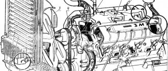
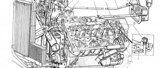
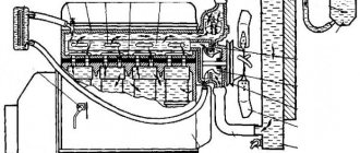
Motor design
The cylinder blocks of the YaMZ-238 diesel engine are made of gray cast iron. The cylinder liners are also made of a special carbide material. The power unit has two heads (one in each row of cylinders). Also inside the motor housing, the designers placed a forged crankshaft along with counterweights and supports. All eight engine pistons are made of aluminum alloy. Each of them has three compression rings and two oil scraper rings. Retaining rings are necessary to limit the movement of the floating piston pins. Also in the cylinder block are forged steel connecting rods with an oblique connector on the lower head. To start the engine, a starter is used, in the housing of which there is a flywheel with a ring gear.
MAZ lubrication system: design features and operating principle
A properly functioning MAZ lubrication system increases engine life
The internal combustion engines of multi-ton trucks use the MAZ mixed lubrication system. It is designed to ensure effective lubrication of the parts of the cylinder-piston group of the power unit by spraying and supplying under pressure. In addition, parts are lubricated when oil flows by gravity into the engine crankcase. Motor oil cools bearings and other parts that heat up during friction, and also removes wear products into the oil pan, extending the life of the parts.
Main device of the system
To perform the assigned functions, the MAZ lubrication system consists of the following parts:
Pressurized oil is supplied through oil lines to lubricate the camshaft main and connecting rod bearings, piston pins, bearings on which the camshaft rotates, rocker arm and pusher bushings, rod ends, as well as the oil pump drive and its bearings. Thanks to the spraying of oil, the mirror surface of the cylinder block liners, camshaft cams, drive gears and rolling bearings is lubricated.
Principle of operation
To create pressure in the line, the oil poured into the engine is sucked by a gear-type oil pump from the sump through a special intake with a filter mesh. The pump consists of a radiator and a discharge (main) section. The discharge part is designed to pump lubricant into the main line through a series-connected filter, which provides rough cleaning. Structurally, the filter is equipped with a bypass valve, which is activated when there is a difference in pressure in the inlet and outlet pipes, which occurs in the event of contamination of the filter element. After opening the valve, the oil flows directly into the line, bypassing the filter element.
After undergoing rough cleaning, the lubricant is pumped into the central line. Next, through special channels made in the cylinder block, it is supplied to the bearings on which the engine crankshaft rotates. Through a system of channels in the crankshaft and connecting rods, oil is pumped under pressure to the camshaft bearings, supplied to the axles of the pushrods and along the rods to lubricate the valve actuators.
A centrifugal-type fine filter element is connected parallel to the main line, through which the lubricant is supplied to the parts of the cylinder-piston group. The element is designed to allow no more than 10% of the lubricant circulating in the system to pass through. After cleaning, the technical fluid is drained into the crankcase (sump) of the power unit. The filter centrifuge is driven by a flow of working fluid under high pressure. The oil, purified by centrifugal force, flows into the oil pan through two nozzles. Mechanical impurities and microparticles are thrown towards the plane of the body and form a sediment. When servicing the filter elements, the resulting contamination is removed.
To cool the working medium circulating in the engine lubrication system, a radiator is connected. An air-cooled tubular type unit is used. It is mounted in front of the radiator of the engine cooling system. The radiator is activated using a special tap. The need for lubricant cooling arises when the truck is operated at air temperatures above 15°C, as well as in severe conditions involving high loads and low speeds.
System protection
In order to ensure stable operation of the MAZ lubrication system, the design includes valves. The pressure reducing valve is installed in the discharge part of the oil pump. Its task is to return the lubricant to the pan at increased pressure at the outlet pipe, exceeding 7.5 kg/sq.cm. A safety valve is mounted in the radiator part of the oil pump. It is adjusted to operate at a pressure of 0.80 -1.2 kg/sq.cm.
The drain valve is mounted at the bottom of the cylinder block and is designed to stabilize the pressure. The device opens when the pressure level in the line reaches 5.0 kg/sq.cm.
Typical faults and troubleshooting methods
When operating a MAZ truck, the following lubrication system malfunctions characteristic of a diesel engine are possible:
- increasing the oil level to a critical value;
- increased lubricant consumption;
- a sharp drop in pressure in the main line;
- smooth reduction in pressure during engine operation.
The main defect of the system is increased or decreased pressure of the circulating oil. The readings are monitored using a pressure indicator mounted on the instrument panel. Before checking parts, you must make sure that the standard measuring device is working properly. For this purpose, a lubricant pressure control indicator is connected to the circuit to verify the readings.
Motor lubrication system
The lubrication system of the diesel engine at the Yaroslavl plant operates in mixed mode. Its main element is the oil cooler, which is installed next to the engine housing. This system also includes two filter elements:
- Full flow oil filter with replaceable filter element.
- Fine oil filter operating by centrifugal force. It is equipped with a jet drive.
At the same time, the manufacturer allows the installation of a coarse filter instead of a full-flow one. Under high pressure, the lubricant is supplied to:
- crankshaft connecting rod and main bearings;
- camshaft bearings;
- bushings of the upper heads of connecting rods;
- pusher bushings;
- rod supports;
- oil pump bushing;
- valve rocker arm bushing.
Lubricant for the fuel pump and speed controller comes from the engine lubrication system. Gears, camshaft cams, and rolling bearings are lubricated by splash lubricant. In this case, the following pressure is created in the oil system during engine operation:
- At nominal speeds - from 400 to 700 kPa.
- At rated speed during idle - not less than 100 kPa.
TRUCKS GAZ, ZIL, KAMAZ, URAL, MAZ, KRAZ
_________________________________________________________________________________________
Design and details of cooling and lubrication systems of the YaMZ-238 engine
Cooling system of the YaMZ-238 diesel engine The cooling system of the YaMZ-238 diesel engine of the MAZ-5516, MAZ-64229, 6303 and Kraz-255, 6510, Kraz-65101, 65055 vehicles (Fig. 17) is liquid, circulating, including a water pump , liquid-oil heat exchanger, fan, thermostats.
Rice. 17. Diagram of the cooling system of the YaMZ-238 diesel engine 1 – water pump; 2 – cavity of the liner cooling block; 3 – water cavity in the block head; 4 – longitudinal water channel; 5 – turbocharger; 6 – right water pipe; 7 – connecting pipe; 8 – inlet pipe; 9 – thermostat; 10 – tee with connecting tubes; 11 – bypass tube; 12 – plug; 13 – inlet pipe of the liquid-oil heat exchanger; 14 – fan; 15 – transverse water channel; A – coolant supply from the water radiator; B – to the cabin heater; B – air release; G – supply of charge air to the air-to-air cooler; D, F – to the radiator; E - from the air-to-air charge air cooler to the cylinders. In addition, the cooling system of the YaMZ-238 diesel engine includes a water radiator, an air-to-air charge air cooler and a remote thermometer installed on the vehicle. During operation of the YaMZ-238 diesel engine, the circulation of coolant in the cooling system is created by a centrifugal pump. From the water pump of the YaMZ-238 engine of the MAZ-5516, MAZ-64229, 6303 and Kraz-255, 6510, Kraz-65101 cars (1), the liquid enters the transverse channel 15 and then along the right longitudinal channel 4 into the water cavity of the right row of cylinders, and into the left row of cylinders - through the inlet pipe of the liquid-oil heat exchanger 13, cooling the oil in two elements, then into the left longitudinal channel. In order for the coolant to pass through the liquid-oil heat exchanger, a plug 12 is pressed into the front cover of the distribution gears. Next, the coolant from the water cavities of the cylinders through the guide channels enters the cylinder heads to the most heated surfaces - the exhaust channels and injector cups and is then collected in the drainage basins. pipes 6. When a cold YaMZ-238 engine is heated, the channels connecting the drainage pipes to the radiator are closed by thermostat valves 9. The coolant circulates through the tee with connecting pipes 10 and the bypass pipe 11 to the water pump, bypassing the radiator, which speeds up engine warming up. When the YaMZ-238 water cooling system reaches a temperature of 80°C, the thermostat valves open, the heated liquid enters the water radiator, where it gives off heat to the air flow created by fan 14, after which it again goes to the water pump. When coolant temperature drops, thermostats automatically direct all coolant flow directly to the water pump, bypassing the radiator. Thus, through thermostats, the optimal thermal operating conditions of the YaMZ-238 engine are ensured. Diesel water pump YaMZ-238 The water pump (pump) YaMZ-238 is of centrifugal type, installed on the front wall of the cylinder block and driven by a V-belt from a pulley mounted on the front end of the crankshaft. The design of the YaMZ-238 diesel pump for MAZ-5516, MAZ-64229, 6303 and Kraz-255, 6510, Kraz-65101 vehicles is shown in Figure 18.
Rice. 18. Water pump (pump) of diesel engine YaMZ-238 1 – drive pulley; 2 – retaining ring; 3 – bearings; 4 – roller; 5 – water release; 6 – end seal; 7 – pump housing; 8 – sealing ring; 9 – water pump pipe; 10 – impeller; 11 – impeller plug; 12 – sealing ring; 13 – sealing ring bushing; A – mechanical seal; B – drainage hole In the cast iron pump casing 7, an impeller 10 pressed onto roller 4 rotates, creating a flow of coolant. The YaMZ-238 water pump roller is mounted on two ball bearings 3 with a one-sided seal. When assembling the pump, the bearing cavity is filled with Litol lubricant for the entire service life of the pump without additional lubrication. The bearing cavity of the YaMZ-238 pump is sealed with a self-clamping end seal. To monitor the tightness of the mechanical seal, there is a drainage hole “B” in the pump housing. Drive pulley 1 is pressed onto the pump shaft. The water pump of the YaMZ-238 diesel engine is marked on the housing 236-1307010-B1. The YaMZ-238 diesel engines of the MAZ-5516, MAZ-64229, 6303 and Kraz-255, 6510, Kraz-65101 vehicles are equipped with a friction fan drive designed to turn the fan on and off depending on operating conditions. The use of friction drive of the YaMZ-238 diesel engine makes it possible to: Ensure optimal thermal conditions of the engine. Reduce fuel consumption by reducing power losses due to fan operation. Increase the reliability of the gear drive of the engine by reducing dynamic loads on the gears. Reduce engine warm-up time. Improve comfort by maintaining an appropriate cabin climate and reducing noise. Lubrication system of the YaMZ-238 diesel engine The lubrication system of the YaMZ-238 diesel engine of the MAZ-5516, MAZ-64229, 6303 and Kraz-255, 6510, Kraz-65101 vehicles is mixed, with a “wet” sump (Fig. 19).
Rice. 19. Diagram of the lubrication system of the YaMZ-238 diesel engine with a single-section oil pump and liquid-oil heat exchanger 1 – oil sump; 2 – oil intake; 3 – oil pump; 4 – pressure reducing valve; 5 – liquid-oil heat exchanger; 6 – oil filter; 7 – bypass valve; 8 – filter signal lamp; 9 – centrifugal oil purification filter; 10 – camshaft; 11 – pusher axis; 12 – crankshaft; 13 – differential valve; 14 – piston cooling nozzle; 15 – valve of the piston cooling system; 16 – turbocharger; 17 – heat exchanger bypass valve; 18 – fan drive switch; 19 – fan drive; 20 – Injection pump Oil pump 238B-1011014-A with a capacity of 140 l/min (Fig. 20) sucks oil from the crankcase through a suction pipe with an intake and supplies it to the system through a series-connected liquid-oil heat exchanger. Rice. 20. Oil pump YaMZ-238 1 – intermediate gear; 2 – axis of the intermediate gear; 3 – drive shaft; 4 – housing cover; 5 – driven shaft-gear; 6 – body; 7 – drive gear; 8 – key; 9 – thrust flange A bypass valve is installed in the heat exchanger body (plate). When the pressure difference before and after the heat exchanger reaches 274±40 kPa (2.8±0.40 kgf/cm2), the valve opens and part of the oil is supplied directly to the oil line. From the liquid-oil heat exchanger, oil enters the channels of the block through a differential valve designed to maintain constant pressure in the system. When the pressure rises above 520 kPa (5.2 kgf/cm2), part of the oil is drained into the crankcase. Next, through the channels in the block, part of the oil through the valve of the YaMZ-238 diesel piston cooling system flows to the piston cooling nozzles and then drains into the crankcase. The valve of the piston cooling system of cars MAZ-5516, MAZ-64229, 6303 and Kraz-255, 6510, Kraz-65101 stops the oil supply to the injectors when the oil pressure in the lubrication system is below 130 - 165 kPa (1.30 - 1.65 kgf/ cm2). The other part goes into the oil filter (Fig. 21). Rice. 21. Oil filter YaMZ-238 1 – filter housing; 2 – cap gasket; 3 – lock cover; 4 – filter cap; 5 – filter element; 6 – cap head; 7 – filter element gasket; 8 – valve plunger; 9 – valve spring; 10 – alarm spring; 11 – moving contact of the signaling device; 12 – fixed contact; 13 – terminal A bypass valve is installed in the filter housing. When the pressure difference before and after the filter reaches 200 - 250 kPa (2.0 - 2.5 kgf/cm2), the valve opens and part of the crude oil is supplied directly to the oil line. By the time the bypass valve begins to open, the moving and fixed contacts of the alarm will close. At this moment, a warning light connected to the signaling device terminal lights up in the driver’s cabin. Such an increase in pressure can occur when the filter element is clogged or the oil has a high viscosity (for example, when starting the engine in the cold season). The filter element of the YaMZ-238 oil filter is made either of non-woven material stretched over a metal frame, or of special filter paper. From the filter, oil flows into the central oil channel, and from there, through a system of channels in the block, to the bearings of the crankshaft and camshaft. From the YaMZ-238 crankshaft bearings of MAZ-5516, MAZ-64229, 6303 and Kraz-255, 6510, Kraz-65101 vehicles, oil is supplied through oil channels in the crankshaft and connecting rods to the bearings of the upper connecting rod heads. From the YaMZ-238 camshaft, oil is directed in a pulsating flow to the axis of the pushers, and from there, through the pusher channels, cavities of the rods and rocker arms, it flows to all the rubbing pairs of the valve drive, and through the outer pipe to the bearings of the turbocharger, speed controller and high-pressure fuel pump. The bearing of the intermediate gear of the YaMZ-238 oil pump drive is also lubricated under pressure. Unit drive gears, camshaft cams, rolling bearings, and cylinder liners are splash lubricated. A pressure reducing valve is installed on the front flange of the outlet pipe of the YaMZ-238 oil pump, which transfers oil back into the crankcase at a pressure at the pump outlet above 700 - 800 kPa (7.0 - 8.0 kgf/cm2). To stabilize the pressure, a differential valve is included in the lubrication system of the YaMZ-238 engine, adjusted to start opening at 490 - 520 kPa (4.9 - 5.2 kgf/cm2). Oil pressure is monitored in the central oil channel. Rice. 22. Centrifugal oil purification filter YaMZ-238 1 – filter cap; 2, 7 – washers; 3 – cap nut; 4 – rotor fastening nut; 5 – thrust washer; 6 – rotor nut; 8, 14 – rotor bushings; 9 – rotor cap; 10 – rotor; 11 – reflector; 12 – sealing ring; 13 – cap gasket; 15 – rotor axis; 16 – filter housing; 17 – rotor nozzle; A – from the system under pressure; B – draining oil into the crankcase The YaMZ-238 centrifugal oil purification filter (Fig. 22), included in the lubrication system in parallel after the oil filter, allows up to 8% of the oil passing through the lubrication system. The YaMZ-238 filter for cars MAZ-5516, MAZ-64229, 6303 and Kraz-255, 6510, Kraz-65101 is designed for fine filtration of oil. The oil is cleaned under the action of centrifugal forces when the rotor rotates. Jets of oil coming out of the nozzle at high speed create a torque that causes the rotor to rotate. Mechanical impurities in the oil are thrown “to the wall” of the rotor cap 9 under the influence of centrifugal forces, forming a dense layer of deposits on its internal surfaces, which should be periodically removed. The purified oil is drained into the crankcase. Additional centrifugal oil purification is also carried out in the cavities of the connecting rod journals of the YaMZ-238 crankshaft. YaMZ-238 diesel turbocharger The YaMZ-238 diesel engine of MAZ-5516, MAZ-64229, 6303 and Kraz-255, 6510, Kraz-65101 vehicles is equipped with a turbocharger that uses the energy of exhaust gases to supercharge the engine. By increasing the mass of air entering the cylinders, the YaMZ-238 turbocharger promotes more efficient combustion of the increased dose of fuel. This increases engine power at moderate thermal stress. The design of the YaMZ-238 diesel engine turbocharger The YaMZ-238 diesel engine turbocharger (Fig. 23) consists of a single-stage centrifugal compressor and a radial centripetal turbine.
Rice. 23. Turbocharger YaMZ-238 1 – compressor wheel fastening nut; 2 – thrust bearing; 3 – bolt; 4 – compressor housing; 5 – insert; 6 – compressor housing cover; 7 – sealing ring; 8 – compressor plate; 9 – bolt; 10 – bolt-stopper; 11 – turbine plate; 12 – bearing housing; 13 – turbine housing spacer; 14 – turbine wheel with shaft; 15 – turbine housing; 16 – sealing rings; 17 – bushing; 18 – bolt; 19 – oil discharge screen; 20 – thrust washers; 21 – sealing ring; 22 – screw; 23 – compressor wheel The turbine wheel 14 and the compressor wheel 23 are located at opposite ends of the rotor shaft in cantilever relative to the bearing sleeve 17. The impeller 23 of the centrifugal compressor is a semi-open type, with blades curved against rotation, cast from an aluminum alloy. It is pressed onto the shaft and secured with nut 1 installed with sealant. Turbine impeller 14 is a semi-open type, with radial blades, made by casting from a heat-resistant alloy. It is connected to the shaft using friction welding. The YaMZ-238 turbine housing is made of heat-resistant cast iron. Gas is supplied to the turbine wheel through two tapering channels. At the end of the turbine housing there are studs for fastening the exhaust pipeline. The compressor housing 4, insert and bearing housing cover 6 are made of aluminum alloy. The bearing housing cover 6 is attached to the bearing housing with bolts 3 using sealant. The turbocharger of the YaMZ-238 diesel engine uses a plain bearing 17 in the form of a sleeve made of aluminum alloy. It is installed in the bore of the cast iron bearing housing 12 and is held against axial movements by a stopper bolt 10. The YaMZ-238 turbocharger bushing is lubricated under pressure from the engine lubrication system. A carefully balanced rotor is installed in a sleeve 17. The axial forces acting on the rotor are absorbed by a thrust bearing 2. At each end of the rotor shaft, split sealing rings 16, made of special cast iron, are installed. The YaMZ-238 diesel turbocharger is attached to the exhaust manifolds by the turbine housing. The outlet pipe of the compressor housing is connected through pipes and the charge air cooler to the engine intake manifolds.
_________________________________________________________________________________________
- GAZ-3307 clutch maintenance
- Steering system GAZ-3307
- Gearbox parts for GAZ-3307
- Maintenance of the rear axle GAZ-3307
- Maintenance of the fuel system of the D-245 diesel engine
- Clutch GAZ-3309 with a diesel engine
- Operations for disassembling the GAZ-3309 gearbox
- GAZ-3309 front axle service
- Repair of cardan shafts of GAZ-3309 cars
_________________________________________________________________________________________
_________________________________________________________________________________________
- Operations for assembling basic components of the ZIL-130 engine
- Service and repair operations for the ZIL-130 gearbox
- Maintenance and repair of ZIL-130 clutch
- Repair and adjustment of the rear axle ZIL-130
_________________________________________________________________________________________
- KAMAZ-4310, 43118, 43114
- KAMAZ-5320, 55111, 53212, 5511, 55102
- KAMAZ-65115, 6520, 65117
- KAMAZ-4308
- Engine KAMAZ-740
_________________________________________________________________________________________
- Parts of the cylinder block and head of the YaMZ-236 engine
- Service maintenance of the YaMZ-236 piston group and crankshaft
- Diagnostics and technical adjustments of the YaMZ-236 engine
- Design and adjustment of fuel injection pump and injectors of the YaMZ-236 engine
- Cylinder block and piston YaMZ-238
- Components of the YaMZ-238 diesel fuel supply system
- Design and adjustment of the fuel injection pump of the YaMZ-238 diesel engine
- Technical design of the YaMZ-239 gearbox
_________________________________________________________________________________________
- Components of the front axle and steering rods of the Maz-5516, 5440
- Steering system of Maz-5516, 5440 cars
- Clutch and gearbox parts Maz-5516, 5440
- Maintenance of drive axles of MAZ-5516, 5440 vehicles
- Power steering for Maz-5551, 5335 cars
- Maintenance of cardan transmission of Maz-5551, 5335 cars
- Maintenance and adjustment of clutch MAZ-5551, 5335
- Repair and service of the rear axle of MAZ-5551, 5335 cars
_________________________________________________________________________________________
- Gearbox Ural-4320
- Construction and adjustment of Ural-4320 bridges
- Maintenance of transfer case Ural-4320
- Steering components Ural-4320
_________________________________________________________________________________________
- Servicing the KRAZ-255, 260 gearbox
- Steering mechanism and power steering Kraz-255, 260
- Adjustments and repairs of the power steering cylinder and steering rods of the Kraz car
- Drive axle components and drive shafts Kraz-255, 260
Cooling system elements
The cooling system in YaMZ-238 (photo attached in the article) is liquid, circulation. It includes a number of basic elements, such as:
- pump for pumping liquid;
- heat exchanger;
- several thermostats that regulate the supply of cooling to the cylinders;
- a fan that supplies air to the cabin and to the engine.
The YaMZ-238 engine has a turbo cooling system (a photo of the power unit is in the article) consists of the following components:
- A pump designed for constant circulation of water.
- The cavity where the cartridge cooling unit is located.
- Water cavity in the block head.
- A channel for the passage of water.
- Compressor.
- Right cooling pipe.
- Connecting tube.
- Inlet pipe.
- Thermostat.
- Tee with tubes.
- Bypass tube.
- Stub.
- Oil heat exchanger pipe.
- Fan.
- Water channel located transversely.
- The supply of fluid used to cool the engine from the radiator to the heater in the cabin, to the air exhaust system, to the radiator.
- Charge air supply system to the cooler and radiator.
- A system for moving cooling air from the cooler to the engine cylinders.
In addition to the above, the cooling system of the YaMZ-238 unit consists of a radiator, a charge air cooler, and a thermometer. All this equipment is installed on the car.
Design + maintenance of the YaMZ-238 diesel cooling system
The engine cooling system (Fig. 1) is liquid, circulation, including a water pump, liquid-oil heat exchanger, fan, thermostats
In addition, the cooling system includes a water cooler, an air-to-air charge air cooler and a vehicle-mounted remote thermometer.
During engine operation, the circulation of coolant in the cooling system is created by a centrifugal pump.
From the water pump 1, the liquid enters the transverse channel 15 and then through the right longitudinal channel 4 into the water cavity of the right row of cylinders, and into the left row of cylinders through the inlet pipe of the liquid-oil heat exchanger 13, cooling the oil in two elements, then into the left longitudinal channel .
In order for the coolant to pass through the liquid-oil heat exchanger, a plug 12 is pressed into the front cover of the distribution gears.
Next, the coolant from the water cavities of the cylinders through the guide channels enters the cylinder heads to the most heated surfaces - exhaust channels and nozzle cups and then collects in drainage pipes 6.
When a cold engine is heated, the channels connecting the drainage pipes to the radiator are closed by thermostat valves 9.
The coolant circulates through the tee with connecting pipes 10 and bypass pipe 11 to the water pump, bypassing the radiator, which speeds up engine warming up.
When the coolant reaches a temperature of 80˚ C, the thermostat valves open, the heated liquid enters the water radiator, where it gives off heat to the air flow created by fan 14, after which it again goes to the water pump.
When coolant temperature drops, thermostats automatically direct all coolant flow directly to the water pump, bypassing the radiator.
Thus, through thermostats, the optimal thermal operating conditions of the engine are ensured.
Water pump
The water pump is a centrifugal type, mounted on the front wall of the cylinder block and driven by a V-belt from a pulley mounted on the front end of the crankshaft.
The design of the water pump is shown in Figure 2. In the cast iron housing 7 of the pump, an impeller 10 pressed onto roller 4 rotates, creating a flow of coolant.
The pump shaft is mounted on two ball bearings 3 with a one-sided seal.
When assembling the pump, the bearing cavity is filled with Litol-24 lubricant GOST 21150-87 for the entire service life of the pump without additional lubrication.
The bearing cavity of the pump is sealed with a self-clamping end seal.
To monitor the tightness of the mechanical seal, there is a drainage hole “B” in the pump housing. Drive pulley 1 is pressed onto the pump shaft.
The water pump is marked on the body 236-1307010-B1.
For repairing a water pump, see the article “Repairing a MAZ water pump.”
Cooling System Maintenance
To ensure normal engine operation, fulfill the following requirements:
1. Fill the cooling system with the recommended special low-freezing liquids or, in exceptional cases, for a short time with clean soft water.
2. Pour coolant through a funnel with a mesh using clean containers.
3. Monitor the temperature of the coolant, maintaining it within 75 – 90ºС.
4. To avoid the occurrence of deformations of the heads and jacket of the cylinder block, add coolant to the cooling system of a warm engine gradually and always during operation.
5. If the cooling system is filled with water, then regularly flush the cooling system with clean water using a special flushing gun, and if it is not available, with a strong stream of clean water, preferably pulsating.
Systematically remove scale from the cooling system.
6. When using Antifreeze as a coolant, it is necessary to periodically monitor its color.
If “Antifreeze” acquires a red-brown color, this indicates its aggressiveness towards the structural materials of engine parts. In this case, the “Antifreeze” must be replaced, having first flushed the cooling system.
7. Monitor the serviceability of the mechanical seal of the water pump impeller, keeping in mind that coolant leaking into the water pump bearings damages them.
A malfunction of the mechanical seal is indicated by water leaking from the drain hole (Fig. 4) on the water pump housing, which must not be clogged.
A pump with a faulty seal must be repaired.
8. In case of temperature violation, check the serviceability of thermostats and their gaskets.
The starting temperature of the main thermostat valve should be 80 ± 2ºС (indicated on the thermostat body).
The valve must open completely, moving at least 8 mm from its seat. Replace the faulty thermostat with a new one.
9. To prevent the radiator from defrosting, when operating in winter conditions, the engine cooling system when using thermostats with a drain valve must be filled only with low-freezing liquid.
These thermostats are designated T117-06 or TS107-06M1, are made of stainless steel (instead of brass on previously used thermostats) and have been installed on engines since March 2007.
Removing scale from the cooling system
Remove scale from the cooling system with a solution of technical Trilon B (TU 6-01-634–71) in water with a concentration of 20 g/l.
Trilon is a white powder, non-toxic, easily soluble in water, and does not cause foaming of water when it is heated and boiled.
Pour Trilon solution into the cooling system.
After one day of engine operation (at least 6–7 hours), drain the used solution and refill with fresh one.
Continue washing for four to five days. After finishing the flushing, pour water containing 2 g/l Trilon into the cooling system.
In the absence of Trilon B, scale can be removed from the cooling system with a solution consisting of soda ash (washing soda) in an amount of 0.5 kg per 10 liters of water and kerosene 1 kg per 10 liters of water.
Pour the solution into the cooling system for 24 hours, of which the engine must be in operating mode for at least 8 hours, then drain the solution while hot, and after cooling the engine, flush the cooling system with clean water.
Checking the coolant (water) level in the cooling system.
Open (with the engine cool) the radiator caps and heater filler pipe. The normal fluid level (with the cabin heater valve open) should be at the level of the upper edge of the radiator cooling tubes.
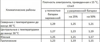
Concentrated low-freezing Tosol-A is used as a coolant (it is poisonous), diluted with soft and clean water in a proportion depending on the climatic zone of the vehicle’s operation (see table).
| Temperature surrounding air, ˚s | Name liquids | Liquid composition by volume, in% | Liquid density at a temperature mixture +20˚s, g/cm3 | |
| Antifreeze-A concentrated | The water is clean | |||
| Up to -40 | Antifreeze A-40 | 56 | 44 | 1,077…1,085 |
| Up to -65 | Antifreeze A-65 | 65 | 35 | 1,085…1,095 |
Draining coolant from the cooling system and heater
To drain the coolant from the system, place the car on a horizontal platform or on a platform inclined forward. Open the four taps located on the heater boiler 3 (Fig. 1), the heater pump unit 5, the lower radiator tank 4, the lower pipe 2 of the engine water pump.
In this case, the heater valve, radiator filler plugs and heater filler pipe must be open.
If one of the taps is clogged, clean it with wire.
To drain fluid from the expansion tank, lift it.
If water was used in the cooling system, turn on the heater pump unit for 10... 15 s to remove it from the pump.
To avoid overheating, starting the engine without coolant is prohibited.
Filling the cooling system with low-freezing liquid
Close the coolant drain valves.
Open the filler pipe/heater plug, then the cabin heater valve and fill the cooling system through the radiator filler neck.
Check its tightness.
Adjusting the tension of drive belts
Check the tension of the drive belts of the water pump, generator and hydraulic coupling of the fan drive by pressing the middle of the largest branch of the belt with a force of 4 kgf (Fig. 3).
The belts should bend by 15... 22 mm. If they sag more or less, adjust their tension.
Adjust the tension of the drive belts of water pump 3 and generator I by changing the position of the generator relative to the axis of its fastening, releasing nuts 7 and 2.
Adjust the tension of the hydraulic coupling drive belts 6 using the tensioning device 4, loosening the nut 5 securing the lever and moving it with the pulley around the axis, inserting a knob into the hole at the end of the lever.
Adjusting fan operating modes
If valve 4 (Fig. 4) of the fluid coupling switch is set to position “B” (mark on the switch body), the temperature of the coolant in the system is automatically maintained within 80...95°C.
When the tap is set to position "O", the fan is turned off. At the same time, it can rotate at a low frequency.
If the tap is set to the “P” position, the fan is constantly on (blocked).
The use of this mode is permissible only for a short time in case of possible malfunctions of the fluid coupling or its switch.
If, when the fan is operating in automatic mode, the temperature of the coolant in the system rises above 105 °C, it is necessary to adjust the stroke of the switch rod by shifting the adjusting washers 1.
On the new switch, all the washers are located above the thermal power sensor 3; in case of violations of the thermal regime, they must be sequentially transferred under the sensor, and after moving all the washers and the need for the next adjustment, the thermal power sensor must be replaced.
The tightening torque of nut 2 securing the thermal power sensor should not exceed 2 ... 2.3 kgf.m.
Check the blinds and their drive.
If necessary, establish the reason for their incomplete opening or closing. Eliminate possible delays.
Cooling principle
During normal operation of the YaMZ-238 engine from MAZ, liquid circulation in the cooling system is created due to the operation of a centrifugal pump. The pump pumps coolant into the transverse channel, and then it passes through the longitudinal channel and enters the water cavity of the cylinders located in the right row. Cooling fluid enters the remaining cylinders of the engine through the inlet pipe. In this way, it is possible to cool the oil in two elements of the power unit at once.
Next, the antifreeze enters the left longitudinally located channel. To allow coolant to flow into the liquid-oil heat exchanger, engineers pressed a plug into the front gear cover for distribution. Then the antifreeze enters the cylinder heads through the tubes, cooling the most heated surface, such as exhaust channels and injector cups. The liquid is then drained into several drainage pipes. During the warm-up of a newly started engine, the cooling system does not function.
The movement of antifreeze is prevented by thermostat valves. The liquid, which serves to cool the engine from overheating, circulates through the connecting tubes, the bypass pipe through the water pump. At the same time, it does not enter the radiator, due to which the power unit heats up to operating temperature. After the antifreeze heats up to 80 degrees Celsius, the thermostat valves open. The liquid heated to the required temperature enters the cavities of the water radiator, where it heats the flow of air entering due to the operation of the fan. The antifreeze then flows back to the water pump.
At the moment when the temperature of the coolant decreases, the thermostats direct it to the pump, bypassing the radiator. Thus, thanks to the blocking of the thermostats, optimal thermal conditions are ensured in the engine.
Cooling system of YaMZ-238PM and YaMZ-238FM engines
Fuel efficiency, engine power and engine service life largely depend on the efficiency of the cooling system. Increased demands are placed on the cooling system of a turbocharged engine, in which the thermal operating conditions of the engine are more intense. The optimal temperature of the coolant at the outlet of the cylinder head is 75 - 98°C. The engine under this thermal regime develops maximum power, consumes the least amount of fuel and operates with minimal wear.
At temperatures below 75°C, the fuel combustion process worsens and the wear of piston group parts increases. Fuel injected into the combustion chamber does not burn completely. Some of the unburned fuel turns into small solid particles of coke (black smoke), some condenses and washes away the oil film from parts and the engine. When the engine overheats, the pressure in the lubrication system drops, the lubricating properties of the oil deteriorate, scuffing of friction surfaces, warping and cracks of parts with a high operating temperature (block head) are possible.
The cooling system of the YaMZ-238PM and YaMZ-238FM engines (Fig. 10) is liquid, closed type, with forced circulation of coolant. A special all-season liquid based on TOCOL-A concentrate is used as a coolant. The main units of the cooling system are a tubular-band, four-row radiator 7, expansion tank 5, water pump 70, fan, thermostats 7, remote thermometer and radiator shutter.
Rice. 10. Cooling system: 1 — thermostat; 2 — steam pipe; 3 — plug of the filler neck of the tank; 4 — radiator connecting hose with the tank; 5 - expansion tank; b - neck for filling coolant; 7 - radiator; 8 — connecting hose of the tank with the water pump pipe; 9 — water pump pipe; 10 - water pump; 11 — bypass tube; 12 — hole for installing a thermometer sensor; I - air release when filling the cooling system during warming up with a pre-heater; II - coolant drain to the radiator; III - supply of coolant from the radiator; IV - supply of coolant to the air brake compressor; U - hot water outlet to the cabin heater
The cooling system works as follows. The water pump takes fluid from the lower radiator tank and pumps it through the channels in the cover of the timing gears into the water jackets of the right and left rows of cylinders, respectively. Then, through the channels of each of the water jackets, the liquid rises up, washes off the outer surface of the cylinder liners and absorbs heat and heats up. Under the pressure created by the pump, the liquid rises higher and enters the water jackets of the cylinder heads through the guide holes and, first of all, to the hottest areas - the exhaust valves and injector cups. By washing and cooling the outer surfaces of the combustion chambers, exhaust pipes, guide valves and injector cups, the liquid is additionally heated.
From the cylinder head, the heated liquid exits through two channels into the drainage pipelines located on both rows of cylinders of the block. From the drainage pipelines through thermostats, the heated liquid flows through two hoses into the upper radiator tank, from which it descends through tubes into the lower tank. Passing through the radiator tubes, the liquid is cooled by the air flow created by the fan. The liquid cooled in the radiator is again pumped from the lower tank by a water pump into the engine water jackets.
When the coolant temperature is below 70°C, as well as at the beginning of the engine warm-up (the fluid temperature has not yet reached 70°C), the thermostats automatically direct the flow of fluid to the water pump through the bypass tube (bypassing the radiator). With such fluid circulation with the radiator turned off, the engine quickly warms up due to the heat released during fuel combustion. When the fluid temperature rises above 70° C, the thermostats open and the fluid from the drainage pipes flows back into the radiator and then into the water pump.
The coolant temperature is also regulated (except for thermostats) using a radiator shutter, which is controlled from the driver's cab. The coolant temperature is controlled by a remote fluid temperature indicator mounted on the instrument panel in the driver's cabin.
The expansion tank is designed to improve the thermal operating conditions of the engine by increasing the static pressure on the suction of the water pump and thereby increasing its flow as a result of preventing cavitation. To do this, the expansion tank is connected to the water distribution pipe of the pump via a hose. The expansion tank also serves to compensate for changes in the volume of coolant during its expansion, allows you to control the degree of filling of the system with coolant, and also ensures the removal of air from the system.
A steam-air plug with two valves is installed on the expansion tank - inlet (air) and outlet (steam). The exhaust valve maintains an excess pressure of 50 kPa in the cooling system, and the intake valve prevents the creation of vacuum in the system when the engine cools. The inlet valve opens and communicates the cooling system with the atmosphere at a vacuum of 1 - 13 kPa.
The water pump (Fig. 11) is centrifugal type; driven by a belt from the crankshaft pulley. An impeller 9, cast from gray cast iron, rotates inside an aluminum alloy housing. The impeller is pressed onto roller 11, from. in which, on the opposite side, a collapsible adjustable pulley is fixed, consisting of a hub 23 and a sidewall 24 of the pulley. Between the hub and the sidewall, steel shims 25, 1 mm thick, are installed, through which the tension of the pump drive belt is adjusted.
Rice. 11. Water pump: 1 — oil seal; 2 - pump housing; 3 - bushing; 4 — stud for fastening the inlet pipe; 5 - seal retaining ring; 6 — thrust ring of the oil seal; 7 — oil seal spring; 8 — oil seal cuff; 9 — impeller; 10 - cover; 11 — roller; 12 - nut; 13 — lock washer; 14 — bypass nipple of the water thermostat tube; 15 and 16 — ball bearings; 17 — gaskets; 18 — oil seal housing; 19 — oil seal bushing; 20 — nut for fastening the pulley sidewall; 21 — lock washer; 22 - nut; 23 — pulley hub; 24 - sidewall of the pulley; 25 — adjusting shims; 26 - grease fitting
To prevent liquid from entering the cavity with lubricant, an end-type seal (cuff 8) is installed on the part of the shaft located inside the impeller. The thrust ring 6 has four projections that fit into the corresponding slots in the impeller and rotates together with the shaft 11. The ring is pressed by a spring 7 to the polished end of the sleeve 3 made of corrosion-resistant steel, pressed into the housing, and creates a movable seal. The oil- and petrol-resistant rubber cuff is pressed against the shaft on one side by clips, and on the other by spring 7 to ring b. This reduces the gap between the ring and the shaft. The cuff, spring and ring inserted into the impeller are secured with a retaining spring ring 5.
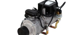
Water pump
In the KAMAZ cooling system with YaMZ-238, the water pump (also called a “pump”) is placed on the front wall of the cylinder block. It rotates via a belt pulley that is mounted on the end of the crankshaft. The pump in the YaMZ-238 cooling system for MAZ-54322 and MAZ-64227 vehicles consists of the following parts:
- drive pulley;
- retaining ring;
- several bearings;
- roller;
- water dumper;
- mechanical seals;
- pump body;
- O-rings;
- a pipe connected to the water pump;
- impeller;
- impeller plug;
- bushing to the O-ring;
- drainage hole.
Spare parts for Ural, Kraz, MAZ, Kamaz trucks. Engine parts YaMZ-236, YaMZ-238
__________________________________________________________________________
__________________________________________________________________________
Cooling and lubrication systems for diesel engine YaMZ-238
___________________________________________________________________________ Cooling system of the YaMZ-238 diesel engine The cooling system of the YaMZ-238 diesel engine of the MAZ-5516, MAZ-64229, 6303 and Kraz-255, 6510, Kraz-65101, 65055 vehicles (Fig. 17) is liquid, circulating, including water pump, liquid-oil heat exchanger, fan, thermostats. Rice. 17. Diagram of the cooling system of the YaMZ-238 diesel engine 1 – water pump; 2 – cavity of the liner cooling block; 3 – water cavity in the block head; 4 – longitudinal water channel; 5 – turbocharger; 6 – right water pipe; 7 – connecting pipe; 8 – inlet pipe; 9 – thermostat; 10 – tee with connecting tubes; 11 – bypass tube; 12 – plug; 13 – inlet pipe of the liquid-oil heat exchanger; 14 – fan; 15 – transverse water channel; A – coolant supply from the water radiator; B – to the cabin heater; B – air release; G – supply of charge air to the air-to-air cooler; D, F – to the radiator; E - from the air-to-air charge air cooler to the cylinders. In addition, the cooling system of the YaMZ-238 diesel engine includes a water radiator, an air-to-air charge air cooler and a remote thermometer installed on the vehicle. During operation of the YaMZ-238 diesel engine, the circulation of coolant in the cooling system is created by a centrifugal pump. From the water pump of the YaMZ-238 engine of the MAZ-5516, MAZ-64229, 6303 and Kraz-255, 6510, Kraz-65101 cars (1), the liquid enters the transverse channel 15 and then along the right longitudinal channel 4 into the water cavity of the right row of cylinders, and into the left row of cylinders - through the inlet pipe of the liquid-oil heat exchanger 13, cooling the oil in two elements, then into the left longitudinal channel. In order for the coolant to pass through the liquid-oil heat exchanger, a plug 12 is pressed into the front cover of the distribution gears. Next, the coolant from the water cavities of the cylinders through the guide channels enters the cylinder heads to the most heated surfaces - the exhaust channels and injector cups and is then collected in the drainage basins. pipes 6. When a cold YaMZ-238 engine is heated, the channels connecting the drainage pipes to the radiator are closed by thermostat valves 9. The coolant circulates through the tee with connecting pipes 10 and the bypass pipe 11 to the water pump, bypassing the radiator, which speeds up engine warming up. When the YaMZ-238 water cooling system reaches a temperature of 80°C, the thermostat valves open, the heated liquid enters the water radiator, where it gives off heat to the air flow created by fan 14, after which it again goes to the water pump. When coolant temperature drops, thermostats automatically direct all coolant flow directly to the water pump, bypassing the radiator. Thus, through thermostats, the optimal thermal operating conditions of the YaMZ-238 engine are ensured. Diesel water pump YaMZ-238 The water pump (pump) YaMZ-238 is of centrifugal type, installed on the front wall of the cylinder block and driven by a V-belt from a pulley mounted on the front end of the crankshaft. The design of the YaMZ-238 diesel pump for MAZ-5516, MAZ-64229, 6303 and Kraz-255, 6510, Kraz-65101 vehicles is shown in Figure 18.
Rice. 18. Water pump (pump) of diesel engine YaMZ-238 1 – drive pulley; 2 – retaining ring; 3 – bearings; 4 – roller; 5 – water release; 6 – end seal; 7 – pump housing; 8 – sealing ring; 9 – water pump pipe; 10 – impeller; 11 – impeller plug; 12 – sealing ring; 13 – sealing ring bushing; A – mechanical seal; B – drainage hole In the cast iron pump casing 7, an impeller 10 pressed onto roller 4 rotates, creating a flow of coolant. The YaMZ-238 water pump roller is mounted on two ball bearings 3 with a one-sided seal. When assembling the pump, the bearing cavity is filled with Litol lubricant for the entire service life of the pump without additional lubrication. The bearing cavity of the YaMZ-238 pump is sealed with a self-clamping end seal. To monitor the tightness of the mechanical seal, there is a drainage hole “B” in the pump housing. Drive pulley 1 is pressed onto the pump shaft. The water pump of the YaMZ-238 diesel engine is marked on the housing 236-1307010-B1. YaMZ-238 diesel engines of MAZ-5516, MAZ-64229, 6303 and Kraz-255, 6510, Kraz-65101 vehicles are equipped with a friction fan drive designed to turn the fan on and off depending on operating conditions. The use of friction drive of the YaMZ-238 diesel engine makes it possible to: Ensure optimal thermal conditions of the engine. Reduce fuel consumption by reducing power losses due to fan operation. Increase the reliability of the gear drive of the engine by reducing dynamic loads on the gears. Reduce engine warm-up time. Improve comfort by maintaining an appropriate cabin climate and reducing noise. Lubrication system of the YaMZ-238 diesel engine The lubrication system of the YaMZ-238 diesel engine of the MAZ-5516, MAZ-64229, 6303 and Kraz-255, 6510, Kraz-65101 vehicles is mixed, with a “wet” sump (Fig. 19). Rice. 19. Diagram of the lubrication system of the YaMZ-238 diesel engine with a single-section oil pump and liquid-oil heat exchanger 1 – oil sump; 2 – oil intake; 3 – oil pump; 4 – pressure reducing valve; 5 – liquid-oil heat exchanger; 6 – oil filter; 7 – bypass valve; 8 – filter signal lamp; 9 – centrifugal oil purification filter; 10 – camshaft; 11 – pusher axis; 12 – crankshaft; 13 – differential valve; 14 – piston cooling nozzle; 15 – valve of the piston cooling system; 16 – turbocharger; 17 – heat exchanger bypass valve; 18 – fan drive switch; 19 – fan drive; 20 – Injection pump Oil pump 238B-1011014-A with a capacity of 140 l/min (Fig. 20) sucks oil from the crankcase through a suction pipe with an intake and supplies it to the system through a series-connected liquid-oil heat exchanger. Rice. 20. Oil pump YaMZ-238 1 – intermediate gear; 2 – axis of the intermediate gear; 3 – drive shaft; 4 – housing cover; 5 – driven shaft-gear; 6 – body; 7 – drive gear; 8 – key; 9 – thrust flange A bypass valve is installed in the heat exchanger body (plate). When the pressure difference before and after the heat exchanger reaches 274±40 kPa (2.8±0.40 kgf/cm2), the valve opens and part of the oil is supplied directly to the oil line. From the liquid-oil heat exchanger, oil enters the channels of the block through a differential valve designed to maintain constant pressure in the system. When the pressure rises above 520 kPa (5.2 kgf/cm2), part of the oil is drained into the crankcase. Next, through the channels in the block, part of the oil through the valve of the YaMZ-238 diesel piston cooling system flows to the piston cooling nozzles and then drains into the crankcase. The valve of the piston cooling system of the MAZ-5516, MAZ-64229, 6303 and Kraz-255, 6510, Kraz-65101 cars stops the oil supply to the injectors when the oil pressure in the lubrication system is below 130 - 165 kPa (1.30 - 1.65 kgf/ cm2). The other part goes into the oil filter (Fig. 21). Rice. 21. Oil filter YaMZ-238 1 – filter housing; 2 – cap gasket; 3 – lock cover; 4 – filter cap; 5 – filter element; 6 – cap head; 7 – filter element gasket; 8 – valve plunger; 9 – valve spring; 10 – alarm spring; 11 – moving contact of the signaling device; 12 – fixed contact; 13 – terminal A bypass valve is installed in the filter housing. When the pressure difference before and after the filter reaches 200 - 250 kPa (2.0 - 2.5 kgf/cm2), the valve opens and part of the crude oil is supplied directly to the oil line. By the time the bypass valve begins to open, the moving and fixed contacts of the alarm will close. At this moment, a warning light connected to the signaling device terminal lights up in the driver’s cabin. Such an increase in pressure can occur when the filter element is clogged or the oil has a high viscosity (for example, when starting the engine in the cold season). The filter element of the YaMZ-238 oil filter is made either of non-woven material stretched over a metal frame, or of special filter paper. From the filter, oil flows into the central oil channel, and from there, through a system of channels in the block, to the bearings of the crankshaft and camshaft. From the YaMZ-238 crankshaft bearings of the MAZ-5516, MAZ-64229, 6303 and Kraz-255, 6510, Kraz-65101 vehicles, oil is supplied through the oil channels in the crankshaft and connecting rods to the bearings of the upper connecting rod heads. From the YaMZ-238 camshaft, oil is directed in a pulsating flow to the axis of the pushers, and from there, through the pusher channels, cavities of the rods and rocker arms, it flows to all the rubbing pairs of the valve drive, and through the outer pipe to the bearings of the turbocharger, speed controller and high-pressure fuel pump. The bearing of the intermediate gear of the YaMZ-238 oil pump drive is also lubricated under pressure. Unit drive gears, camshaft cams, rolling bearings, and cylinder liners are splash lubricated. A pressure reducing valve is installed on the front flange of the outlet pipe of the YaMZ-238 oil pump, which transfers oil back into the crankcase at a pressure at the pump outlet above 700 - 800 kPa (7.0 - 8.0 kgf/cm2). To stabilize the pressure, a differential valve is included in the lubrication system of the YaMZ-238 engine, adjusted to start opening at 490 - 520 kPa (4.9 - 5.2 kgf/cm2). Oil pressure is monitored in the central oil channel. Rice. 22. Centrifugal oil purification filter YaMZ-238 1 – filter cap; 2, 7 – washers; 3 – cap nut; 4 – rotor fastening nut; 5 – thrust washer; 6 – rotor nut; 8, 14 – rotor bushings; 9 – rotor cap; 10 – rotor; 11 – reflector; 12 – sealing ring; 13 – cap gasket; 15 – rotor axis; 16 – filter housing; 17 – rotor nozzle; A – from the system under pressure; B – draining oil into the crankcase The YaMZ-238 centrifugal oil purification filter (Fig. 22), included in the lubrication system in parallel after the oil filter, allows up to 8% of the oil passing through the lubrication system. The YaMZ-238 filter for cars MAZ-5516, MAZ-64229, 6303 and Kraz-255, 6510, Kraz-65101 is designed for fine filtration of oil. The oil is cleaned under the action of centrifugal forces when the rotor rotates. Jets of oil coming out of the nozzle at high speed create a torque that causes the rotor to rotate. Mechanical impurities in the oil are thrown “to the wall” of the rotor cap 9 under the influence of centrifugal forces, forming a dense layer of deposits on its internal surfaces, which should be periodically removed. The purified oil is drained into the crankcase. Additional centrifugal oil purification is also carried out in the cavities of the connecting rod journals of the YaMZ-238 crankshaft. YaMZ-238 diesel turbocharger The YaMZ-238 diesel engine of MAZ-5516, MAZ-64229, 6303 and Kraz-255, 6510, Kraz-65101 vehicles is equipped with a turbocharger that uses the energy of exhaust gases to supercharge the engine. By increasing the mass of air entering the cylinders, the YaMZ-238 turbocharger promotes more efficient combustion of the increased dose of fuel. This increases engine power at moderate thermal stress. The design of the YaMZ-238 diesel engine turbocharger The YaMZ-238 diesel engine turbocharger (Fig. 23) consists of a single-stage centrifugal compressor and a radial centripetal turbine. Rice. 23. Turbocharger YaMZ-238 1 – compressor wheel fastening nut; 2 – thrust bearing; 3 – bolt; 4 – compressor housing; 5 – insert; 6 – compressor housing cover; 7 – sealing ring; 8 – compressor plate; 9 – bolt; 10 – bolt-stopper; 11 – turbine plate; 12 – bearing housing; 13 – turbine housing spacer; 14 – turbine wheel with shaft; 15 – turbine housing; 16 – sealing rings; 17 – bushing; 18 – bolt; 19 – oil discharge screen; 20 – thrust washers; 21 – sealing ring; 22 – screw; 23 – compressor wheel The turbine wheel 14 and the compressor wheel 23 are located at opposite ends of the rotor shaft in cantilever relative to the bearing sleeve 17. The impeller 23 of the centrifugal compressor is a semi-open type, with blades curved against rotation, cast from an aluminum alloy. It is pressed onto the shaft and secured with nut 1 installed with sealant. Turbine impeller 14 is a semi-open type, with radial blades, made by casting from a heat-resistant alloy. It is connected to the shaft using friction welding. The YaMZ-238 turbine housing is made of heat-resistant cast iron. Gas is supplied to the turbine wheel through two tapering channels. At the end of the turbine housing there are studs for fastening the exhaust pipeline. The compressor housing 4, insert and bearing housing cover 6 are made of aluminum alloy. The bearing housing cover 6 is attached to the bearing housing with bolts 3 using sealant. The turbocharger of the YaMZ-238 diesel engine uses a plain bearing 17 in the form of a sleeve made of aluminum alloy. It is installed in the bore of the cast iron bearing housing 12 and is held against axial movements by a stopper bolt 10. The YaMZ-238 turbocharger bushing is lubricated under pressure from the engine lubrication system. A carefully balanced rotor is installed in a sleeve 17. The axial forces acting on the rotor are absorbed by a thrust bearing 2. At each end of the rotor shaft, split sealing rings 16, made of special cast iron, are installed. The YaMZ-238 diesel turbocharger is attached to the exhaust manifolds by the turbine housing. The outlet pipe of the compressor housing is connected through pipes and the charge air cooler to the engine intake manifolds.
_________________________________________________________________________
_________________________________________________________________________
_________________________________________________________________________
- Cardan shafts and power take-off Ural-4320
- Transmission gearbox Ural-4320
- Bridges Ural-4320
- Transfer case Ural-4320
- Steering Ural-4320
- Truck cranes and cranes based on trucks
_________________________________________________________________________
_________________________________________________________________________
- Cylinder block and cylinder head YaMZ-236 HE2, YaMZ-236 BE2
- Checking and adjusting YaMZ-236
- Power system and lubrication system YaMZ-236
- Driven and driven clutch discs YaMZ-236, 238
- Cooling and lubrication systems YaMZ-238
- Fuel injection pump YaMZ-238
_________________________________________________________________________
- Kamaz diesel engine
- Repair and adjustment of Kamaz power steering
- Kamaz-152 gearbox with divider
- Gearbox parts for Kamaz-5320 gearbox
- Kamaz transfer case and driveshafts
- Kamaz gearbox repair
- Clutch KamAZ-5320
- Construction of Kamaz-4310 drive axles
- Power steering MAZ-5551, 5549, 5335, 5336, 5337
- Front axle and steering rods MAZ-5551, 5549, 5335, 5336, 5337
- Clutch adjustment MAZ-5551, 5549, 5335, 5336, 5337
- Adjustment and repair of gearboxes MAZ-5551, 5549, 5335, 5336, 5337
- Repair and maintenance of the rear axle MAZ-5551, 5549, 5335, 5336, 5337
- Front axle parts and steering rods MAZ-5516, 5440
- Steering Maz-5516, 5440
- Details of driving axles Maz-5516, 5440
- Clutch device ZIL-130
- Repair of ZIL-130 gearbox
- Repair of rear axle ZIL-130
- Basic parts of the ZIL-130 engine
- Transfer case and power take-off ZIL-131
- Drive axles ZIL-131
- Steering ZIL-131
- Maintenance of ZIL-645 engine parts
Pump operating principle
The cooling system in the YaMZ-238 turbo operates due to its main element - a pump (water pump). Inside its body, made of cast iron, an impeller rotates, which is pressed onto a roller. This creates an air flow.
To ensure rotation of the roller in the YaMZ-238 cooling system, it is mounted on two ball bearings. The bearing cavities are tightly packed with lubricant (lithol), which is designed for the entire service life of the pump. Replacement of this material is not required.
To ensure a tight mechanical seal in the pump body, a drainage hole is made. The drive pulley is pressed onto the shaft.
Each water pump, which powers the cooling system in the YaMZ-238, is marked with a digital and letter designation.
Choosing a pump for the engine
To operate the oil cooling system in the YaMZ-238, various water pumps are installed, but the product labeled YaMZ-236/238 turned out to be the most reliable. Its parameters are ideal for the operation of powerful power units with the same letter and digital index.
Such a pump is capable of distilling liquid through the cooling system at a speed of about 30 liters per minute with a shaft torque of 0.52 units. The weight of such a product does not exceed 9 kg. The dimensions of the pump may vary depending on the type and power of the engine for which it is intended.
In addition to their dimensions, pumps for normal operation of the oil cooling system in the YaMZ-238 may differ in connection dimensions.
Antifreeze or antifreeze is used as a coolant in the system. This means that the pump must operate at an ambient temperature of -40 to +50 degrees Celsius and withstand the same temperature of the coolant that it circulates through the system. Also, the pump in the YaMZ-238 cooling system, with a volume of 11,150 cubic centimeters, must work properly if it is filled with water, which heats up to 100 degrees Celsius while moving through the pipes through the radiator and engine housing.
Design of the MAZ-500 cooling system
The engine cooling system is liquid, closed type, with forced circulation of coolant.
The main units of the cooling system are (Fig. 26): radiator, water pump 8, fan 5, thermostats 3 and remote thermometer.
During engine operation, fluid circulation in the cooling system is created by a centrifugal pump driven by a V-belt 7 from the crankshaft pulley 6.
The cooling system works as follows. The water pump / (Fig. 27) takes liquid from the lower tank 11 of the radiator and pumps it through the channels in the timing gear cover into jackets 2 and 6 of the right and left rows of cylinders, respectively. Then, through the channels of each of the water jackets, the liquid rises up, washes the outer surface of the cylinder liners and, absorbing heat, heats up. Under the pressure created by the pump, the liquid rises higher and enters the water jackets of the cylinder heads through the guide holes and, first of all, to the hottest places—the exhaust valves and injector cups. By washing and cooling the outer surfaces of the combustion chambers, exhaust pipes, guide valves and injector cups, the liquid is additionally heated. From the cylinder head, the heated liquid exits through two channels into the drainage pipelines 5, located on both rows of cylinders of the block. From the drainage pipelines through thermostats, the heated liquid flows through two durite (rubberized) hoses into the upper tank 9 of the radiator, from which it descends through tubes 10 into the lower tank of the radiator.
Passing through the radiator tubes, the hot liquid, thanks to the large cooling surface, transfers heat to the air flow created by fan 12.
The liquid cooled in the radiator is again pumped from the lower tank by a water pump into the engine water jackets. When the coolant temperature drops below 70° C, as well as at the beginning of the engine warming up, when the liquid temperature has not yet reached 70° C, the thermostats automatically direct the entire fluid flow directly to the water pump through the bypass tube 8 past the radiator. With such fluid circulation with the radiator turned off, the engine quickly warms up due to the heat released during fuel combustion. When the fluid temperature rises above 70 ° C, the thermostats open and the fluid from the drainage pipes flows back into the radiator, and from there into the water pump.
Rice. 26. Cooling system:
L - to the cabin heater; B and C - to the radiator; G - to the compressor; D - from the radiator; E - from the starting heater; 1 - installation location of the thermometer sensor; 2 - valve for bleeding air when filling the cooling system while the engine is warming up with the starting heater; 3 - thermostat; 4—bypass tube: 5—fan; 6—crankshaft pulley; 7 — pump drive belt; 8 - water pump
The best temperature of the coolant at the outlet of the cylinder head is 75-98°C. At this thermal regime, the engine develops maximum power, consumes the least amount of fuel and operates with minimal wear.
27. Engine cooling diagram:
1 - water pump: 2 - water jacket of the right row of cylinders; 3 — liquid temperature indicator; 4—sensor; 5 - drainage pipelines; 6 — water jacket of the left row of the cylinder; 7 — thermostats: 8 — bypass tube; 9 — upper radiator tank; 10 — radiator tubes; 11—lower radiator tank: 12—fan.
At temperatures below 70° C, the combustion process deteriorates and wear of the piston group increases. Fuel injected into the combustion chamber burns incompletely. Some of the unburnt fuel turns into fine solid particles of coke (black smoke), while some condenses and washes away the oil film from engine parts.
When the engine overheats, the pressure in the lubrication system drops, the lubricating properties of the oil deteriorate, scuffing of rubbing surfaces, warping and cracks of parts with a high operating temperature (block head) are possible.
The coolant temperature is also regulated (except for thermostats) using radiator shutters, which are controlled by a handle from the driver's cab.
The coolant temperature is controlled by a remote fluid temperature indicator 3 installed on the instrument panel in the driver's cabin.
Cooling system capacity 32 l. The cooling system is filled through the radiator neck, which is closed with a plug.
The centrifugal-type water pump (Fig. 28) is installed on the right side of the timing gear cover and is driven by a V-belt from a pulley mounted on the front end of the engine crankshaft.
Inside the housing 8, made of aluminum alloy, an impeller 6, cast from gray cast iron, rotates. The impeller is pressed onto shaft 4, on which, on the opposite side, a dismountable adjustable pulley, consisting of a hub 12 and a pulley sidewall 13, is attached using a key and a nut. Between the hub and the sidewall, steel shims 14 1 mm thick are installed, with the help of which the tension of the pump drive belt is adjusted.
The pump shaft rotates in two single-row ball bearings installed in the housing.
The ball bearing grease is injected through the grease nipple until it appears in the inspection hole.
Rice. 28. Water pump:
1 - gasket; 2 — housing cover; 3—spring; 4 - pump shaft; 5—cuff: 6—impeller; 7— sealing washer; 8 — body; 9 — fitting: 10 — retaining ring; 11— bushing; 12 — pulley hub; 13 — — pulley sidewall: 14 — shims
To prevent liquid from entering the cavity with lubricant, an end-type seal (cuff 5) is installed on the part of the shaft located inside the impeller.
The textolite washer 7 has four protrusions that fit into the corresponding slots of the impeller, and thus rotates together with the shaft 4. The washer is pressed by the spring 3 to the polished end of the sleeve made of stainless steel, pressed into the body, and creates a movable seal.
The cuff 5 made of oil- and petrol-resistant rubber is pressed against the shaft with clips on one side, and with a spring 3 against the washer 7 on the other, thereby sealing the gap between the washer and the shaft.
The cuff, spring and washer inserted into the impeller are secured with a retaining spring ring 10.
The pump housing is closed with a cover 2, sealed with a paronite gasket 1. Through the housing opening, closed by this cover, the pump is assembled and disassembled.
A fitting 9 is screwed into the pump housing, connecting the pump to the bypass pipe, through which liquid is bypassed from the block when the thermostats are closed during the engine warming up.
The thermostat is designed to maintain a constant temperature of the liquid in the cooling system during engine operation. When the engine is running, depending on the load, speed and ambient temperature, the coolant temperature constantly changes. It was mentioned above that the most favorable coolant temperature is 75-98 ° C. To maintain the specified fluid temperature on the engine, thermostats are used that automatically regulate the flow of coolant from the cylinder heads to the radiator.
The engine has two thermostats installed in the water collection pipes of both parts of the block.
The thermostat (Fig. 29) is two-valve, accordion type. The main parts of the thermostat: body 2, cylinder 8, central valve 4 and ring valve 3.
Rice. 29. Thermostat:
1 — cylinder clip; 2 — thermostat housing; 3 - ring valve; 4 - central valve: 5 - rod; 6 — window in the body; 7 - cover; 8 - cylinder
The corrugated container 8 is filled with a low-boiling liquid and sealed. The bottom of the cylinder is attached to the thermostat body with a clip; on the opposite side, a rod 5 is attached to the cylinder cap 7, connected simultaneously to the ring valve 3.
At the end of the tube, a central valve 4 is screwed on, which, when the cylinder is compressed, is tightly pressed against the seat of the housing 2, blocking its outlet.
The thermostat body, made of brass, has two side windows 6, which are closed by a ring valve when the central valve is fully open.
The thermostat is installed in box 2 (Fig. 30), attached with screws to the drainage pipeline 1. A sealing gasket is installed between the pipeline and the thermostat box.
The thermostat box is divided by partition 5 into two parts.
One part (cavity B) communicates with the bypass tube, and the other (cavity A) communicates with the upper radiator tank.
The thermostat works as follows. When the temperature of the liquid in the cooling system is below 70 ° C, the central valve is closed, and the liquid flowing from the block into the drainage pipes passes between the corrugated cylinder and the thermostat body, exits through two windows 4 and fills the internal cavity B of the thermostat box. From here the liquid enters the bypass tube 4 (see Fig. 26) and the water pump.
Rte. 30. Upper water pipe with thermostat:
A and B - thermostat cavities: 1 - drainage pipeline: 2 - thermostat box; 3 - thermostat; 4 - window; 5 - partition
Thus, the liquid, bypassing the radiator, circulates in the engine block in the so-called small circle. This creates favorable conditions for rapid heating of the liquid. When the coolant temperature reaches about 70 ° C, the cylinder, due to heating and expansion of the low-boiling liquid contained in it, elongates so much that the central thermostat valve begins to open, and the liquid can flow into the cavity of the thermostat box, communicating with the upper radiator tank. In the temperature range of 70-85 ° C, the liquid circulates through the radiator and the bypass tube.
The intensity of fluid circulation through the radiator in this case depends on the degree of opening of the central valve.
When the liquid temperature rises to 85° C, the central valve opens completely, the windows in the thermostat housing are closed with a ring valve and the liquid circulates only through the radiator (in a “large circle”). At high ambient temperatures, if the engine overheats, you can temporarily remove the thermostats while plugging the bypass tube.
The fan is designed to create an intense air flow between the radiator tubes, in which the liquid flowing from the upper radiator tank to the lower one is cooled.
The fan drive (Fig. 31) is gear driven, carried out directly from gear 10 of the camshaft.
Rice. 31. Fan:
1 — coupling hub; 2—rubber ring; 3 — coupling body: 4 — oil seal; 5 — pulley: 6 — fan shaft: 7 — fan housing; 8 — driven gear; 9 — timing gear cover; 10 - drive gear; 11 — impeller
The cast iron housing 7 of the fan is attached to the cover of 9 timing gears with bolts. Fan shaft 6 rotates in two ball bearings installed in the housing.
At the front end of the shaft there is an elastic coupling, to which a six-bladed impeller 11 is bolted, rotating in the radiator casing. The casing is attached to the radiator frame and increases the amount of air passing through.
The elastic coupling consists of a body 3 and a hub 1, which are glued from different sides to a rubber ring 2.
Thus, when starting the engine and with a sharp change in the crankshaft speed, the inertial force arising from the mass of the impeller will be absorbed by the elasticity of the rubber ring, as a result of which the fan shaft is relieved of excessive torsional forces.
A pulley 5 is attached to the shaft using a key to drive the compressor and generator. At the rear end of the shaft, driven gear 8 of the fan drive is mounted on splines.
To prevent oil from leaking out of the fan housing, oil seal 4 is pressed into its outlet hole.
A tubular-tape (snake) radiator with oval-section tubes consists of upper and lower tanks, which are connected to each other by radiator core tubes, as well as side posts forming a frame. The tubes are soldered into the tanks. The upper tank has a neck that is closed with a sealed plug and equipped with a steam outlet tube. The tanks have pipes that connect the radiator with the rest of the cooling system units through flexible rubber-fabric hoses.
Rice. 32. Radiator cap:
1 — steam pipe; 2 — plug body; 3 - locking spring; 4 — exhaust valve spring; 5 — radiator neck; 6 — exhaust valve; 7 — inlet valve; 8 — intake valve spring
Radiators can be installed on a car with three (three-row) or four (four-row) rows of tubes.
Radiator tubes are tinned to improve heat transfer and protect the tubes from corrosion.
To increase the cooling surface, a corrugated brass tape is installed between the tubes along their entire length (its width is equal to the thickness of the radiator), which is soldered to the tubes at the points of contact.
There are two valves in the radiator plug (Fig. 32) that connect the cooling system to the atmosphere to avoid damage to the radiator due to increased pressure when the liquid boils or the presence of vacuum inside it as a result of steam condensation.
Exhaust valve 6 opens when the steam pressure in the system increases to 0.7–1 kg/cm2 and releases steam through steam outlet tube 1. Inlet valve 7 opens at a vacuum of 0.01–0.13 kg/cm2 and lets atmospheric air into the radiator . The release valve, which opens at increased pressure, makes it possible to increase the boiling point.
The MAZ-500 car has 65 fluids in the system up to 119 ° C and, therefore, operates at an increased thermal regime.
The radiator is installed on the frame brackets on rubber cushions and is additionally attached to the side members with braces.
Radiator blinds are plate type. The plates can be fixed in any position. Depending on the degree of opening of the plates, more or less air passes through the radiator, causing the water in the radiator to cool with greater or less intensity. The blinds are controlled from the driver's seat using a cable drive handle. When you pull the handle towards you, the blinds close, when you push them in, they open.
Checking the cooling system
During periodic inspections of the car, mechanics need to pay special attention to the condition of the YaMZ-238 cooling system with a volume of 11,150 cubic centimeters. It is necessary to check the tightness of the pipes and connections in order to prevent antifreeze leakage in time.
To check the engine cooling pump for leaks, it is necessary to increase the pressure in the power unit to 3 kgf/cm2 and maintain it for one minute. You can also check your pump for leaks by running compressed air through the system for 30 seconds.
If the system is sealed, a specialist needs to check the operation of the mechanisms. To do this, you need to rotate the pump shaft. It should rotate freely along its axis.
Pressure in the car engine cooling system
One of the main tasks of engine manufacturers is to increase efficiency, which ideally should reach 100%. But at the moment, internal combustion engines used in cars are far from ideal. During their operation, a significant part of the energy is spent on friction and heating. Due to the resulting heating, cooling systems have to be installed in the car. At the moment, the most common liquid cooling system for a car engine. Coolant (antifreeze or antifreeze) is poured into it, which circulates through the system under pressure, cooling the corresponding units. In this article, we will consider what kind of pressure is created in the cooling system, how this happens, as well as other issues related to the topic.
How pressure is created inside a car's cooling system
The first thing you need to understand is that no special pressure is created in the engine cooling system. The engine units themselves do not care under what pressure the coolant circulates. The main thing is that the engine elements have time to cool sufficiently.
As you know, almost any liquid expands when heated. This also applies to coolant – antifreeze, antifreeze. On average, coolant expands by 10-20% when heated, that is, this is how much its level in the system increases. Since the cooling system is a closed, sealed circuit, pressure builds up when the engine starts and the coolant warms up. Antifreeze presses on the walls of radiators, pipes and other system components inside.
Please note: The expansion tank cap plays an important role in the car’s cooling system. It is a high and low pressure valve, which can, respectively, bleed off excess or, conversely, suck in air from the atmosphere.
Why do you need high pressure inside the cooling system?
If you remember the school physics course, you can easily understand why increased pressure is used in the cooling system. As you know, the higher the pressure, the higher the boiling point of the liquid. Accordingly, if, for example, the pressure is 1 atmosphere, ordinary water will boil at 100 degrees Celsius. But, if you raise the pressure to 2 atmospheres, the boiling point will approach 120 degrees Celsius.
Please note: the example with water above is given for a reason. Until a few years ago, automobile cooling systems used plain water to cool the engine. Since its boiling point is at 100 degrees Celsius, and the operating temperature of the motor is often higher, it was decided to increase the pressure inside the cooling system. In addition, older cooling systems did not seal as well as their modern counterparts.
Coolants that are currently used in a car’s cooling system boil at a temperature of 130-140 degrees, and when in a sealed competition with high pressure, the temperature can reach up to 150 degrees. That is why the problem of engine “boiling” is becoming less and less common.
What is the pressure inside the car cooling system
It’s immediately worth noting that depending on the car, the pressure in the car’s cooling system will differ. Let's give an average value - it is approximately from 1.2 to 2 atmospheres (in rare situations, the pressure can reach up to 2 atmospheres).
Please note: When talking about pressure in relation to a liquid, it is customary to call it not in atmospheres, but in Bars. Accordingly, the pressure in the cooling system in this case is, on average, from 1.2 to 2 Bar.
The pressure in the cooling system can depend on many different factors: the coolant used, the structure of the engine itself, tightness, and so on.
What role does the expansion tank cap play in the cooling system pressure?
An important issue that must be considered is the meaning of the expansion tank cap. It is a valve whose task is to control the pressure inside the hoses and pipes.
Removing the water pump
Many mechanics are interested in what possible malfunctions in the YaMZ-238 cooling system may arise during the operation of the vehicle? Most often, the reason for the disruption of heat exchange between the engine and antifreeze is a breakdown of the pump that distils the coolant. If a malfunction of such a part is detected, it is necessary to find the cause of the failure by disassembling it. Then you need to decide whether to repair the device or proceed with its complete replacement. To disassemble the water pump, the technician must:
- Loosen the pump drive belt and then remove the belt from the pulley.
- After this, you need to drain all the fluid from the system, including the engine and radiator.
- Then you should remove the pipe connected directly to the pump.
- The last operation to dismantle the pump is to remove the pump from the engine. To do this, you need to unscrew the pump housing.
How many liters of antifreeze in Yamz 236?
| Unit | Lubrication system capacity, l |
| YaMZ - 236 HE2, BE2, YaMZ -7601.10 | 24,0 |
| YaMZ -7511.10 | 32,0 |
| YaMZ -238 DE2 | 32,0 |
| YaMZ -6581.10, 6582.10 Euro 3 | 32,0 |
How many liters of coolant are in Yamz 238?
Main indicators of YaMZ-238 filling tanks: Lubrication system volume - 32 liters. The volume of the cooling system, excluding the radiator volume, is 20 liters.
How many liters of coolant is in a Maz?
Fuel tank - 200 l (it is possible to install a tank with a volume of 350 l); cooling system (without heater) - 39 l, antifreeze A-40; engine lubrication system - 33 l, in summer - M-1ODM, in winter - M-8DM (replacements for M-10G2(k) and M-8G2(k);
How to drain antifreeze Yamz 236?
Having loosened the fastening of the YaMZ-236 water pump (pump) drive belt tensioner, remove the belt from the water pump pulley. Drain the engine and radiator coolant. Remove the inlet pipe from the water pump. After unscrewing the fastener, remove the water pump from the engine, being careful not to damage the gasket.
How much oil is poured into the Yamz 236 injection pump?
The total volume of the lubrication system of this engine is 32 liters, while oil is usually filled with 24-28 liters.
How much oil is in a box of maz?
The filling capacity of the box crankcase is 5.5 liters. Oil is poured into the crankcase through the oil filler hole in the top cover of the box, always through a funnel with a fine mesh. The oil level in the crankcase is checked through the control hole on the non-working box.
What kind of oil should I put in the Yamz gearbox?
To lubricate the gearbox, transmission oil TS-14.5 (MRTU 38-1-150-64) with 5% EFO additive should be used. Substitutes: aviation oil MK-22 (GOST 1013-49) in summer and MS-14 (GOST 1013-49) in winter or oil MT-16p (GOST 6360-58) in summer and winter. The filling capacity of the box crankcase is 5.5 liters.
How much oil is in a Yamz 238 box?
The oil level below the inspection hole is not allowed (volume of oil to be filled
7.5 ÷ 8 liters). 3.2 Maintenance after running in the vehicle. After running the car, change the oil in the gearbox housing, clean the oil intake screen and the drain plug magnet from run-in products.
Disassembling the pump
To disassemble a YaMZ brand water pump for further repairs, you must:
- Unscrew the nuts that hold the pipe.
- Remove the pipe from the pump.
- Secure the pulley to prevent shaft rotation.
- Remove the plug by turning it outward from the threaded hole.
- Screw the puller nut into the resulting pulley hole, and then, screwing in the bolt, remove the pulley from the shaft.
- Bend back the guides of the mechanical seal housing, and then remove the cuff with the spring and frame assembly.
- Press the pulley using a special puller.
- Pull the retaining ring out of the pump groove.
- Remove the shaft along with the water release and bearings from the pump body.
- If the mechanical seal body, made of brass, has no visible damage, then it does not need to be pulled out. Otherwise, it must be removed and replaced with a new one.
- This completes disassembly of the pump.
Assembly after repair
After the pump has been completely disassembled, the fault has been identified, all damaged elements have been replaced with new ones, all working parts should be washed and then dried thoroughly. You can use compressed air for this.
Next, you need to assemble the product for further installation on the car engine. To do this, you need to perform a number of operations:
- Press the bearings and water release onto the shaft. In this case, the shaft should be lubricated with diesel engine oil. The bearings must be installed so that the sealing washers are on the outside. All pressing force must be applied only to the inner ring of the bearings.
- Next, it is necessary to fill the open cavities between the bearings, formed after pressing, with special lubricant “Litol-24.
- Lubricate the shaft with previously unused engine oil.
- During the next operation, the shaft assembly must be installed in the water pump housing. It is necessary to provide a fixed stop on the opposite side of the shaft.
- Next, you need to install a mechanical seal made of a brass body.
- Place a rubber cuff assembled with a spring and several frames.
- Next, you should put the cuff on the sealing sleeve.
- Then it is necessary to lubricate the pulley bore with a thin layer, as well as the outer surface of the cuff, which is made of rubber.
- Install the reinforced collar and bushing for sealing.
- Mount the pulley in the rubber collar and bushing for sealing. To avoid various distortions and the occurrence of gases in the YaMZ-238 cooling system, you need to clasp the cuff with both hands and then insert it into the pulley bore.
- Next, you need to press the pump pulley assembly onto the shaft, but before that you should remember to lubricate both parts at the contact points with previously unused engine oil.
- Secure the pulley to prevent it from rotating.
- Screw the cap tightly.
- Install a rubber ring and bushing into the water pump housing.
- Place a ring in the groove of the pipes.
- Connect the pipes of the YaMZ-238 cooling system to the pump.
- Secure the pipes using hardware.
This completes the assembly of the water pump.