Device
The KamAZ crankshaft design includes the following parts:
- Connecting rod and main journals, which are interconnected. Connecting rod type journals have a smaller diameter. They are used as support.
- Counterweight. Helps balance the weight of the piston and connecting rods.
- Knee. Equipped with one crankpin, which is located between two brushes.
- Sliding bearings. They allow the connecting rods in the journals and in the crankshaft mechanism to rotate.
- The shank on which the flywheel is mounted to take power from the crankshaft.
- Flange and brushes.
The difference between KamAZ crankshafts of different models lies in the material used (cast iron or steel), as well as in the number of connecting rod journals.
Repair dimensions of the KamAZ 740 crankshaft
The tables show the dimensions at which restoration of parts of the assembly is allowed:
| Variety | Main neck size (mm) | Bore in cylinder assembly (mm) |
| PO-1 | 94.7 | 100 |
| PO-2 | 94.5 | 100 |
| PO-3 | 94.25 | 100 |
| P10 | 95.0 | 100.5 |
| P11 | 94.75 | 100.5 |
| P12 | 94.5 | 100.5 |
| P13 | 94.25 | 100.5 |
Nominal dimensions of the KamAZ 740 crankshaft for repair and replacement of inserts:
| Designation | Diameter size of connecting rod journal in diameter (mm) | Connecting rod crank hole diameter (mm) |
| PO-1 | 79.75 | 85.0 |
| PO-2 | 79.5 | 85.0 |
| P10 | 80.0 | 85.5 |
| P11 | 79.75 | 85.5 |
| P12 | 79.5 | 85.5 |
| P13 | 79.25 | 85.0 |
| PO-3 | 79.25 | 85.0 |
Dimensions and other characteristics
Parameters and technical indicators of the KamAZ crankshaft:
- crank radius - 4.6 cm;
- radius of extreme counterweights - 8.5 cm;
- radius of middle counterweights - 8.2 cm;
- diameter of the molar neck - 6.4 cm;
- connecting rod journal diameter - 5.8 cm;
- crankshaft flange diameter - 12.2 cm;
- connecting rod journal width - 3.6 cm;
- width of the molar neck - 4 cm;
- number of counterweights - 4;
- protective chamfers - yes;
- piston stroke - 13 cm;
- diameter of cylindrical elements - 12 cm;
- body material - cast iron or steel alloy;
- maximum torque - 2200 rpm;
- repair dimensions - 0.5*0.2 m;
- permissible imbalance - no more than 35 g/cm;
- the entire mechanism including counterweights weighs 76 kg.
What is the price
The average price for a crankshaft is 35,000 rubles.
Crankshaft prices on the market vary widely:
- the average price of a new crankshaft is 35,000 rubles;
- a used crankshaft costs an average of 20,000 rubles (the price depends on the condition of the spare part);
- A Chinese crankshaft costs 15,000-30,000 rubles (depending on the build quality).
It is not recommended to buy spare parts made in China, as their installation can lead to car damage.
Attention! In Moscow, cases of selling Chinese spare parts under the guise of original ones have become more frequent. Be careful when purchasing, check all technical specifications of the product.
Types of Kamaz crankshafts
In recent years, the range of crankshafts produced by Kamaz has expanded significantly. Now the plant produces diesel and environmentally friendly gas engines that meet European quality standards. For each engine there are several types of crankshafts.
Crankshafts from different engines are sometimes interchangeable and sometimes not. To date, the Kamaz company does not provide clear instructions on the types of crankshafts, which is why owners of heavy trucks usually have confusion about which crankshaft is needed specifically for their brand of Kamaz. To solve this problem, a description of the crankshafts is provided below:
- their features;
- differences from each other;
- Possibility of use with different standard motors.
Crankshafts meeting Euro 0 standard
Engines created according to the Euro-0 standard include standard heavy-duty diesel engines 740.10 and engines of the updated version 7403.10, 7408. For the production of crankshafts for these engines, 42ХМФА standard steel is used, which has undergone special treatment with chromium and molybdenum, and is coated with aluminum. Hardening of the production material occurs with high-frequency currents to a depth of 3 millimeters. crankshafts have special plugs. This crankshaft model has now been discontinued.
Crankshafts operating for Euro 1 standard
Engines created according to this standard include heavy-duty engines of the 740.11-240 and -260 series. The design of crankshafts in this series does not include plugs. They are made of metal standard 42ХМФА. Hardening of the metal, as in the previous model, occurs with the help of high-frequency frequency; the Shrovetide channels have an oblique design. crankshafts of this series have only one type of structure. Spare parts from KAMAZ 740 are also suitable for engines of this standard.
Euro 2 engine crankshafts
Engines that meet the Euro 2 standard have different crank radii. That is why the types of crankshafts for different radii have serious differences.
The crank diameter of Kamaz engines is 60 mm (R65). They are equipped with 2 types of crankshafts, which differ from each other in the type of flywheel connection:
- the flywheel is fixed to 8 holes, the type of bolts is M14;
- The flywheel is fixed to 10 holes, the type of bolts being M16.
The 2 types of parts cannot replace each other.
The crank radius of Kamaz engines can also be (you can see the type of crank on your parts) 65 mm. Crankshafts in which the flywheel is secured with 10 M16 bolts are suitable for them. The parts are interchangeable, but there are differences in the hardening method:
- hardening using HDTV;
- hardening by nitriding.
Crankshafts for Euro-3 engine standard
Engines that meet the Euro-3 standard are quite few in number. The crank radius of these engines is 65 mm. In this case, the flywheel can be mounted according to the standard scheme with 8 or 10 bolts. The product is hardened by high frequency currents. They can be replaced with other Euro 2 crankshafts (which have also undergone HDF treatment).
For all crankshafts, the method of mounting the flywheel depends on the type of clutch installed in the car. With the classic configuration, the flywheel is mounted on 8 M14 bolts. On new configuration models, a flywheel connection with 10 M16 bolts is used.
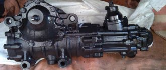
Crankshaft and connecting rod-piston group of Kamaz-740 diesel engine
_______________________________________________________________________________________
Crankshaft of Kamaz-740 diesel engines The Kamaz 740 crankshaft is made of high-quality steel and has five main and four connecting rod journals, hardened with high-frequency heat, which are interconnected by cheeks and mated with them by transition fillets. For uniform alternation of working strokes, the location of the crankpins of the crankshaft is made at an angle of 90°. Two connecting rods are attached to each connecting rod journal of the Kamaz-740 crankshaft: one for the right and one for the left rows of cylinders.
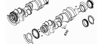
Kamaz-740 crankshaft (Fig. 1) 1 - front crankshaft counterweight; 2 — rear crankshaft counterweight; 3 — oil pump drive gear; 4 — timing gear drive; 5.6- key; 7 - pin; 8- jet; 9 — lightening holes; 10 - oil supply holes in the main journals 11 - oil supply holes to the connecting rod journals. Oil supply to the connecting rod journals is made from the holes in the main journals with 10 straight holes 11. To balance inertial forces and reduce vibrations, the Kamaz-740 crankshaft has six stamped counterweights together with the crankshaft cheeks. In addition to the main counterweights, there are two additional removable counterweights 1 and 2, pressed onto the shaft, and their angular position relative to the crankshaft is determined by keys 5 and 6. A ball bearing is pressed into the bore of the Kamaz-740 crankshaft shank.
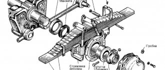
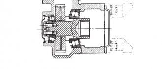
Fig.2. Installation of thrust half rings and crankshaft bearing shells Kamaz-740 1 - upper half ring of the crankshaft thrust bearing: 2 - lower half ring of the crankshaft thrust bearing 3 - upper crankshaft bearing shell; 4- lower crankshaft bearing shell; 5 - cylinder block 6 - rear crankshaft bearing cover 7 - crankshaft. A jet 8 is screwed into the cavity of the front toe of the Kamaz-740 crankshaft, through a calibrated hole through which the splined power take-off shaft for the fluid coupling drive is lubricated. The Kamaz-740 crankshaft is secured against axial movements by two upper half-rings 1 and two lower half-rings 2 (Fig. 2), installed in the grooves of the rear main support of the cylinder block, so that the side with the grooves is adjacent to the thrust ends of the shaft. On the front and rear toes of the KamAZ 740 crankshaft, gear 3 for the oil pump drive and drive gear 4 for the camshaft drive are installed. The rear end of the crankshaft has eight threaded holes for the flywheel mounting bolts, the front toe of the crankshaft has eight holes for attaching the torsional vibration damper. The Kamaz-740 crankshaft is sealed by a rubber cuff 8 (Fig. 3), with an additional sealing element - boot 9. The cuff is located in the flywheel housing 4. The cuff is made of fluorine rubber using the technology of molding the working sealing edge directly in the mold.
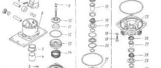
Installation of the flywheel and crankshaft seal cuff Kamaz-740 (Fig. 3) 1 - flywheel; 2- cylinder block; 3- crankshaft; 4 — flywheel housing; 5- gearbox input shaft bearing; 6- washer; 7- flywheel mounting bolt; 8- crankshaft seal collar; 9- cuff boot; 10 — flywheel mounting pin Diameters of Kamaz-740 crankshaft journals: main 95+0.011 mm, connecting rod 80±0.0095 mm. To restore the Kamaz-740 engine, eight repair sizes of liners are provided. Inserts 7405.1005170 P0, 7405.1005171 P0, 7405.1005058 P0 are used when restoring an engine without grinding the crankshaft. If necessary, the crankshaft journals are polished. Tolerances on the diameters of the Kamaz-740 crankshaft journals, holes in the cylinder block and holes in the lower head of the connecting rod during engine repairs should be the same as the nominal sizes of new engines. Kamaz-740 main and connecting rod bearings are made of steel strip coated with a layer of lead bronze 0.3 mm thick, a layer of lead-tin alloy 0.022 mm thick and a layer of tin 0.003 mm thick. The upper 3 (Fig. 2) and lower 4 main bearing shells are not interchangeable. The upper liner has a hole for oil supply and a groove for its distribution. Both shells 4 of the lower connecting rod head are interchangeable. The Kamaz-740 liners are secured against rotation and lateral displacement by protrusions (whiskers) that fit into the grooves provided in the block beds, bearing caps and connecting rod beds. Kamaz-740 liners have design differences aimed at increasing their performance when the engine is boosted by turbocharging, while the marking of the liners has been changed to 7405.1004058 (connecting rod), 7405.1005170 and 7405.1005171 (main). Therefore, when carrying out repair maintenance, it is not recommended to replace the liners with serial ones marked 740.100.., since this will significantly reduce the engine life. The main bearing caps of KamAZ-740 are made of high-strength cast iron of the VCh50 grade. The covers are fastened using vertical and horizontal coupling bolts 3, 4, 5, which are tightened according to a certain pattern with a regulated torque. The Kamaz-740 flywheel is secured with eight bolts 7 (Fig. 3), made of alloy steel with a twelve-sided head, at the rear end of the crankshaft and is precisely fixed with two pins and a mounting sleeve. In order to avoid damage to the surface of the KamAZ-740 flywheel, a washer 6 is installed under the bolt heads (Fig. 3). A ring gear is pressed onto the machined cylindrical surface of the flywheel, with which the starter gear meshes when starting the engine. When performing adjustment work to set the fuel injection advance angle and the thermal clearances in the valves, the KamAZ-740 flywheel is fixed using a clamp. At the same time, the design has the following main differences from the serial one: — the angle of the groove for the retainer on the outer surface of the flywheel has been changed; — the diameter of the bore has been increased to accommodate the washer for the flywheel mounting bolts. Kamaz-740 engines can be equipped with various types of clutches.
Installation of the crankshaft torsional vibration damper (Fig. 4) 1 - damper; 2 — damper mounting bolt; 3 — power take-off half; 4 — coupling half mounting bolt; 5 — washer; 6 - crankshaft; 7 - cylinder block. The Kamaz-740 torsional vibration damper is secured with eight bolts 2 (Fig. 4) on the front toe of the crankshaft. In order to prevent damage to the surface of the damper body, a washer 5 is installed under the bolts. The Kamaz-740 damper consists of a housing in which the flywheel is installed with a gap. The outside of the damper body is closed with a lid. Tightness is ensured by seaming (welding) at the junction of the damper body and the cover. Between the damper body and the Kamaz-740 flywheel there is a high-viscosity silicone liquid, dosed before welding the lid. The damper is centered using a washer welded to the body. Damping of torsional vibrations of the Kamaz-740 crankshaft occurs by braking the damper body, mounted on the toe of the crankshaft, relative to the flywheel in a silicone liquid environment. In this case, braking energy is released in the form of heat. When carrying out repair work, it is strictly forbidden to deform the damper body and cover. A damper with a deformed body or cover is not suitable for further use. Piston group and connecting rods of the Kamaz-740 diesel engine The Kamaz-740 connecting rod is steel, forged, the rod has an I-section. The upper head of the connecting rod is one-piece, the lower one is made with a straight and flat connector. The connecting rod is finally processed together with the cap, so the connecting rod caps are not interchangeable. A steel-bronze bushing is pressed into the upper head of the Kamaz-740 connecting rod, and replaceable liners are installed into the lower one. The cover of the lower head of the Kamaz-740 connecting rod is secured with nuts screwed onto bolts previously pressed into the connecting rod rod. On the cover and rod of the connecting rod there are pairing marks - three-digit serial numbers. In addition, the cylinder serial number is stamped on the connecting rod cover. The Kamaz-740 piston is cast from aluminum alloy with a wear-resistant cast iron insert under the upper compression ring. The Kamaz-740 piston head has a toroidal combustion chamber with a displacer in the central part; it is shifted relative to the piston axis away from the recesses for the valves by 5 mm. The side surface is a complex oval-barrel shape with a reduction in the area of the holes for the piston pin. The skirt has a graphite coating.
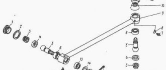
Piston with connecting rod and rings Kamaz-740 assembled 1 - piston; 2 — oil scraper ring; 3 — piston pin; 4, 5 — compression rings; 6 — retaining ring. There is a groove in its lower part that, if assembled correctly, prevents contact of the piston with the cooling nozzle when at BDC. Kamaz-740 pistons are equipped with three rings, two compression and one oil scraper.
Its distinctive feature is the reduced distance from the bottom to the lower end of the upper groove, which is 17 mm. On Kamaz-740 engines, in order to ensure fuel efficiency and environmental performance, selective selection of pistons is used for each cylinder according to the distance from the piston pin axis to the bottom. According to the specified parameter, Kamaz-740 pistons are divided into four groups 10, 20, 30 and 40.
Each subsequent group differs from the previous one by 0.11 mm. Kamaz-740 spare parts are supplied with pistons of the greatest height, therefore, in order to avoid possible contact between them and the cylinder heads in case of replacement, it is necessary to control the over-piston clearance. If the gap between the piston and the Kamaz-740 cylinder head after tightening its fastening bolts is less than 0.87 mm, it is necessary to trim the piston bottom to the amount missing to this value. The pistons of engines 740.11, 740.13 and 740.14 differ from each other in the shape of the grooves for the upper compression and oil scraper rings. Installation of pistons from Kamaz 740.10 and 7403.10 engines is unacceptable. It is allowed to install pistons with piston rings of engines 740.13 and 740.14 on engine 740.11. Compression rings for Kamaz-740 are made of high-strength, and oil scraper rings are made of gray cast iron. On the 740.11 engine, the cross-sectional shape of the compression rings is one-sided trapezoid; during installation, the inclined end should be located on the side of the piston bottom. Compression rings for Kamaz-740 are made of high-strength, and oil scraper rings are made of gray cast iron. On the 740.11 engine, the cross-sectional shape of the compression rings is one-sided trapezoid; during installation, the inclined end should be located on the side of the piston bottom. On engines 740.13 and 740.14, the upper compression ring has a cross-sectional shape of a double-sided trapezoid with a recess at the upper end, which should be located on the side of the piston bottom. The working surface of the upper compression ring of Kamaz-740 is covered with molybdenum and has a barrel-shaped shape. Chrome is applied to the working surface of the second compression and oil scraper rings. Its shape on the second ring of the Kamaz-740 is a cone with a slope towards the lower end; for this characteristic feature the ring is called “minute”. Minute rings are used to reduce oil consumption due to waste; their installation in the upper groove is not permissible. The Kamaz-740 oil scraper ring is box-type with a spring expander having a variable pitch of turns and a ground outer surface.
The middle part of the expander with a smaller pitch of turns when installed on the piston should be located in the ring lock. On the 740.11 engine the ring height is 5 mm, and on the 740.13 and 740.14 engines the ring height is 4 mm. Installing piston rings from other Kamaz engine models can lead to increased oil consumption due to waste. To exclude the possibility of using non-interchangeable parts of the Kamaz-740 piston group when carrying out repair work, it is recommended to use repair kits: - 7405.1000128-42 - for engine 740.11-240; — 740.13.1000128 and 740.30-1000128 — for engines 740.13-260 and 740.14-300. The Kamaz-740 repair kit includes: - piston; - piston rings; — piston pin; — piston pin retaining rings; - cylinder liner; — O-rings of the cylinder liner. Kamaz-740 cooling nozzles are installed in the crankcase of the cylinder block and provide oil supply from the main oil line when it reaches a pressure of 0.8 - 1.2 kg/cm2 (the valve located in each of the nozzles is adjusted to this pressure) into the internal cavity pistons. When assembling the Kamaz-740 engine, it is necessary to monitor the correct position of the injector tube relative to the cylinder liner and piston. Contact with the piston is not permitted. The piston and Kamaz-740 connecting rod are connected by a floating pin 3, its axial movement is limited by retaining rings 6. The pin is made of chromium-nickel steel, the hole diameter is 22 mm. The use of pins with a 25 mm hole is unacceptable, as this disrupts the balancing of the engine.
_______________________________________________________________________________________
_______________________________________________________________________________________
- 970 Elite
- TLB 860
- Cat 422
- Cat 428
- Cat 434
- Cat 444
- 3 CX Super
- 4 CX
- 5 CX
- WZ30-25
- XT860/XT870
_______________________________________________________________________________________
- WB 97S
- WB 93R
- Hyundai H940S
- B110
- B115
- Hidromek HMK 102B
- Hidromek HMK 62SS
_______________________________________________________________________________________
- Mobile cranes
- Cranes manipulators
- Motor graders DZ-122,143
- Excavator EK-14
- Kamaz truck repair
- MAZ truck repair
- TL 65
- TL 120
- TL 310
- Cat 914
- Cat 924
- Caterpillar 950
- Caterpillar 966
_______________________________________________________________________________________
- LW500F
- ZL30G
- ZL50G
- LW321F
- XGMA XG932
- XGMA XG955
- Design of Terex, Komatsu, Cat loaders
- ZW250
- ZW310
- ZW220
- ZW180
- W130
- W170
- W190
- W270
- L34
- Adjusting the D-180 engine
- Transmission T-170
- Assembly of gearboxes T-170, T-130
- Adjusting the T-170 clutch
- Hydraulic and mounted systems T-170
- Main gear T-170, T-130
- Diesel injection pump D-160
- Servo mechanism of clutch T-130, T-170
- Onboard clutches T-130
- Final drive of the T-130 tractor
- Rotation control mechanism T-130
- Hydromechanical transmission TO-18/TO-18B
- Hydraulic system GMP TO-18/TO-18B Amkodor
- Hydraulic system TO-18
- Hydraulic system components TO-18/TO-18B Amkodor
_______________________________________________________________________________________
- Design of rack and pinion hydraulic cylinders
- Types of positive displacement hydraulic pumps
- Rotary screw pumps - Design and operating principle
- Characteristics and design of gear pumps
- Pump control diagram in a closed hydraulic system
- Hydraulic distributor device with proportional control
- Hydraulic systems of special equipment - operation and maintenance
- Application of hydrostatic transmissions for special equipment
- Application of cartridge electrically controlled valves
- Design and diagrams of cartridge plug-in hydraulic valves
- Characteristics of Screw-in Hydraulic Cartridge Valves
- Sequence valve and pressure reducing valve operating diagrams
- Variable displacement hydraulic pump regulator
- Load Sending System for Variable Pumps
- Hydraulic distributors - Control systems
- Control diagrams for working hydraulic units of special equipment
Repair work
Malfunctions of the KamAZ crankshaft and ways to eliminate them:
- Damage to the main or connecting rod journals, deformation of the seats. In this case, it is recommended to grind the parts to the repair size, apply a coating using electric arc surfacing, and weld the electrical contact strip.
- The thread on the oil scraper ring is worn. It is necessary to deepen the thread using a cutter and grind the neck.
- Defective key, seat and ball bearing. In this case, it is necessary to perform milling to match the increased parameters of the keys, make surfacing followed by milling the key, and press in the bushings.
- Damage to the holes for the flywheel mounting pins. It is necessary to unroll the parts to the repair size.
How to remove a bearing
To remove a bearing from the crankshaft, you must:
- Remove all vehicle components that prevent access to the crankshaft.
- Place the power unit block on the stand that is used to repair the engine.
- Remove the flywheel. For comfortable operation, it is recommended to install a locking device on the flywheel crown. Before removal, the position of the mechanism relative to the motor block is noted, and a marking is made as to the sequence in which the mounting bolts were installed.
- Remove the oil pan and oil pump.
- Remove the bearing caps and the connecting rods themselves. They need to be removed along with the pistons.
- Remove the crankshaft.
- Clean seating surfaces.
- Remove the bearing.
How to balance
Procedure for balancing:
- Place the machine in a horizontal position.
- Install the crankshaft on the machine. If there is an imbalance and the shaft begins to rotate around the corner, such an imbalance must be eliminated.
- Using small magnets, determine the exact weight of the metal that needs to be cut. To do this, magnets must be attached to the light side of the flywheel. They are hooked until the crankshaft lies motionless, without overweight. The weight of the magnets is the weight of the metal that must be cut off to balance.
- Remove any chips from the flywheel.
- Trim off excess metal by drilling small holes in the flywheel housing.
- Return the crankshaft back to the vehicle.
How to install
Installing the crankshaft includes the following steps:
- Removing the main bearing cap from the cylinder block.
- Unscrewing the tightening and mounting bolts.
- Selection of main bearing shells in accordance with the diameter of the main journals.
- Selection of thrust rings.
- Checking the liners.
- Installing the upper bearing shells into the cylindrical block, then the lower ones and lubricating them.
- Installing the crankshaft in a vehicle.
- Installing the connecting rod head.
- Screwing the lower and upper half rings.
- Cleaning and lubricating threads in block holes.
- Checking the tightening torque of bolts.
- Inspect the thrust bearing for clearance.
The resistance when tightening the bolts should increase without jerking, smoothly.
Repair kit
The KamAZ 740 series crankshaft repair kit includes a whole set of parts. The main ones:
- Locking and pin elements.
- Pistons with a set of rings.
- Sealing parts.
- Cylinder liner.
The cylinder block is equipped with cooling nozzles, which are necessary to supply lubricating fluid under pressure within 0.8/1.2 atmospheres from the main line. Such indicators are established using correction valves. Oil enters the internal surfaces of the pistons.
When assembling the engine, it is important to ensure precise control of the location of the injector tubes in relation to the cylinders and piston liners. Please note that direct contact with the second part is unacceptable.
To connect the piston to the connecting rod, a floating pin is used, which is made using chrome-nickel steel. To prevent axial displacement of this part, special locking rings are installed.