The implement rises slowly or does not rise at all (does not fall)
The causes of this malfunction and corrective measures may be as follows.
- There is little working fluid in the tank, so the distributor does not work (the fluid must be added to the level).
- The bypass valve hangs due to dirt getting into the valve shank-guide interface; there are foreign particles on the bypass valve seat that prevent it from completely closing; The jet hole in the valve collar (plunger) is dirty. To eliminate a stuck valve, it is necessary to remove the valve and guide from the distributor body, wash them in diesel fuel, clean the jet hole and wipe the valve seat. When reinstalling the bypass valve parts, check that the valve stem moves freely in the guide.
- The safety valve does not close completely due to dirt accumulation under the ball on the edge of the socket hole. Therefore, the distributor bypass valve is fully or partially open and the hitch system does not work. To eliminate the malfunction, it is necessary to briefly hold the distributor handle in the “Forced lowering” position several times in order to wash away dirt from the edge of the safety valve with a flow of working fluid. If dirt cannot be removed in this way, then the distributor must be removed and sent to a repair shop.
- The distributor may be in good working order, but the mounted machine will not lift. This may be for the following reasons:
- The hydraulic system pump is not turned on or the pump spontaneously turns off due to a faulty switching mechanism; leakage of working fluid in the pump
- the shut-off device does not allow working fluid to pass through the oil line
- air leakage through the pump drive shaft seal or through the sealing ring of the suction pipe or oil line fitting, which causes foaming of the working fluid
- faulty power cylinder
- the calibrated hole of the retarding valve is clogged
- increased leakage through the piston o-ring
- jamming in the seat of the piston stroke limitation valve
- the gap between the stop and the shank of the piston stroke limitation valve is less than 10 mm
- Low or high fluid temperature in the hydraulic system tank. In this case, it is necessary to ensure the temperature of the working fluid in the tank is in the range of +30-60°C.
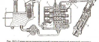
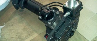
Disassembly and repair of the distributor of the MTZ-80, MTZ-50, YuMZ-6 tractors
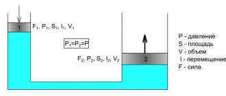
By controlling the spools, it is possible to provide the attachments with different positions by redistributing the hydraulic fluid along the necessary channels.
The rod deflection is allowed no more than 0.1 mm over the entire length. B and D - discharge cavities, channels. The device creates pressure until the second spool operates.
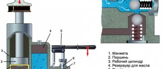
Control channel G is blocked by the cylindrical part of the spool, and the flow of oil through the control channel and the orifice hole of valve 21 stops. In addition, a special repair kit recommended by the company that produces these products can significantly simplify the repair of the MTZ 82 hydraulic distributor. The technical condition of the filter is determined using a KI device, connecting it to the drain pipeline. The spool lock disappears. Only forced lowering requires holding the lever with your hand. When determining the total oil leaks in the spool pair of the distributor and power cylinder, lift the suspended load onto the machine. Distributor: 1 - top cover; 2 - spring; 3 — locking sleeve; 4 - pipeline; 5 - spool; 6 — cover; 7 — lever; 8 and 10 — liners; 9 - sealing ring; 11 — bottom cover; 12 — body; 13 - bypass valve; 14 — rod valve; 15 - nest; 16 - safety valve; 17 — spring; 18 — adjusting screw; 19 - nut; 20 - cap; A - sub-piston cavity; B - discharge channel; B - drain channel; G - control channel of the bypass valve; G and 3 - leads into the working cavities of the cylinders; And - throttling recesses on the edges of the spools.
As a result, the pressure in the above-piston and under-piston zones is equalized, and by the force of spring 18, valve 21 sits in the seat. Remove the control handles and anther plates from the top cover, remove the anthers and o-rings, and remove the spherical spool control levers. The hydraulic redistributor valve goes down under the influence of its own spring. The distributor body has holes for the spools and channels for the passage of oil. The oil approaches the valve through the inclined and axial drillings in the spool. The inner hole of the seat and its end part should clearly form a sharp edge.
When the spool is in a floating position, both spaces can communicate with each other thanks to the drain line. The bypass valve seat is pressed out of the body using a stepped mandrel (Fig.
The distributor may be in good working order, but the mounted machine will not lift. This is not recommended, since not only the conical shut-off part of the valve wears out, but also its seat. Next, pull out the spherical spool control levers. Control channel G is blocked by the cylindrical part of the spool, and the flow of oil through the control channel and the orifice hole of valve 21 stops. Thus, in the RZZR distributor, the bypass valve and, consequently, the oil flow from the pump can be controlled not only by the three spools of the distributor itself, but also by the regulator spools. Safety valve MTZ, hydraulics, adjustment
Related article: tractor with 80 Stalinist
The spool does not automatically return from the "Raise" or "Forced Lower" position
The causes of this malfunction and ways to eliminate them may be the following:
- The response pressure of the safety valve is equal to or lower than the response pressure of the automatic spool return device. This reason is eliminated by changing the adjustment of the response pressure of the automatic spool return device to I-12 MPa (110-125 kgf/cm2) or the safety valve to 13.0-13.5 MPa (130-135 kgf/cm2) in repair shops.
- The bypass valve freezes, as a result of which the required pressure does not develop to activate the automatic device. The method for eliminating this problem is described above.
- The temperature of the working fluid in the tank is above +60°C, therefore, the viscosity is insufficient; resulting in large fluid leaks through the gaps in the automatic spool return device. The temperature of the working fluid of the hydraulic system has increased due to a malfunction of the booster device, therefore, until the malfunction is eliminated, the tractor driver must manually return the handle from the operating positions to “Neutral”. The cause of the malfunction can be eliminated by cooling the working fluid to a temperature of +60-30° C.
- The automatic spool return device is operational, but does not work due to a malfunction of the pump (it does not create the required pressure).
- The spool filter is clogged and the working fluid does not flow into the booster device in sufficient quantities. The malfunction can only be eliminated by disassembling the spool - remove the sleeve, gasket with filter and wash it.
The need for a hydraulic distributor on a tractor
The three-section distributor R-80 3/1 222G is used in the hydraulic system of the Belarus 80 tractor for the following functions:
- protects the system from hydraulic overloads during lifting or forced lowering;
- distributes the flow of hydraulic fluid, which is pumped by a hydraulic pump between system units (hydraulic cylinders, hydraulic motors);
- unloads the system at idle with neutral output due to the transfer of transmission oil into the oil tank;
- connects the working volume of the hydraulic cylinder to drain the process fluid (when operating in a neutral position).
In addition, the hydraulic distributor P80 3/1 222G serves as a basic device on which modifications are made for use on loading units, excavators and road construction equipment. The technical characteristics and parameters of the distributor can be found in the description of the P80 marking, where:
- R – distributor.
- 80 – nominal transmission fluid consumption (l/min).
- 3 – version according to process pressure (permissible 20 MPa, nominal 16 MPa).
- 1 – type of operational purpose (autonomous use in hydraulic systems).
- 222 – three special spools made according to option two.
- G – hydraulic locks (check valves).
Leakage of working fluid
- By spheres of leverage. O-ring worn. To replace the ring, you need to unscrew the anther plate and remove it without removing the corrugated anthers from the levers, remove the control levers, remove the O-rings and replace the worn ones.
- Along the connector of the housing with the covers, along the bolts securing the covers to the distributor body. Fluid leaks through the connectors can occur when the cover gaskets are worn out and if the hydraulic system drain filter is clogged.
- When the filter is clogged, the pressure at the drain increases and the working fluid enters the tank through the filter safety valve. An increase in the pressure of the working fluid at the drain causes the working fluid to leak out through the seals of the distributor caps. In this case, you need to rinse the filter without disturbing the adjustment of the safety valve.
- Worn gaskets of the top and bottom covers must be replaced with new ones. When replacing the top cover gasket, you must unscrew the anther plate and remove it without removing the corrugated anthers from the levers, remove the control levers, remove the cover and replace the gasket. When replacing the lower distributor cap gasket, you must unscrew the nuts securing the triangular flange to the lower cover and remove it, and then unscrew the stud nuts securing the cover to the body, remove it and replace the gasket.
- At the bypass valve guide stop connector. Leakage of working fluid occurs due to wear of the gasket or sealing ring of the guide. It is necessary to unscrew the bolts securing the bypass valve guide stop to the body, remove it, check the condition of the gasket and, if necessary, replace it. If leakage continues after replacing the gasket, the valve guide O-ring must be replaced.
- Through fittings supplying working fluid from the pump to the distributor and from the distributor to consumers, as well as through the plug.
Possible problems with the hydraulic valve
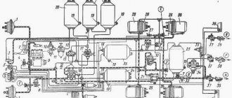
Common malfunctions in the P80 3/1 222G hydraulic distributor installed on the MTZ 80 tractor are:
- wear of the interface in the hydraulic distributor body-spool pair;
- violations in the hydraulic cylinder piston;
- breakdown of pump gears;
- cracking of rubber seals;
- leakage of hydraulic fluid through connecting fittings;
- damage to oil drive pipes.
The design and arrangement of the hydraulic distributor allows the operator to repair these faults manually.
In addition, a special repair kit for the P80 3/1 222G, recommended by the manufacturer, will help make repairs easier.
The reliable, proven design of the P80 hydraulic distributor allows it to be used on the new version of the Belarus 920 tractor, as well as on the multifunctional MTZ 3022.
Source
Types of hydraulic distributors
Hydraulic distributors come in various types. The full classification is quite extensive, so we will briefly look at the main types of distributors:
- Monoblock and sectional.
- Spool, valve and tap valves.
Monoblock ones are equipped with secondary valves to regulate the pressure in the working channels. This allows the distributor to operate more efficiently when used in both simple and complex hydraulic systems.
Sectional ones consist of spool sections with special seals between them. The first section is equipped with a safety valve to protect the hydraulic circuits from overload. The remaining sections are working and are intended for adjusting hydraulic motors and hydraulic cylinders. Sectional distributors can be used in any system.
Spools, valves or taps can be used as a shut-off and control element.
Spool valves are recommended for use in hydraulic systems operating under pressure up to 32 MPa, that is, they are more suitable for machines such as bulldozers, excavators, etc. Valve valves can withstand higher pressures, more than 80 MPa. They are sealed, but are very heavy. Crane valves are auxiliary, used in combination with spool or valve valves. Liquid is directed into them when the valve plug is turned.
Technical conditions [up]
The production of hydraulic equipment, pumps and domestic hydraulic motors requires high precision and strict adherence to the technical conditions of their production.
The hydraulic system and its elements are constantly washed with mineral oil during operation. This promotes heat dissipation, removal of wear products, and the mating parts receive good lubrication. Therefore, by promptly servicing drive elements and replacing spent working fluid, we create all the conditions for a reliable and long service life of the hydraulic drive. If various types of defects were made in the manufacture of hydraulic drive elements, then malfunctions may occur in the operation of the hydraulic systems, which may appear during the operation of a particular unit or due to violations committed during the maintenance of the hydraulic drive - insufficient filtration of the working fluid when filling the hydraulic system.
What malfunctions can occur in the operation of a hydraulic drive? What are the reasons for their occurrence and how to troubleshoot?