Five-furrow mounted plow PLN-5-35 Operation manual
Transcript
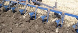
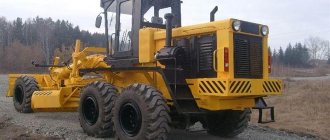
1 Five-furrow mounted plow PLN-5-35 Operating manual 1. INTRODUCTION 1.1 Purpose of the operating instructions This operating manual is a guide for machine operators when assembling, operating, maintaining and storing plows. 2. GENERAL DESCRIPTION AND TECHNICAL CHARACTERISTICS 2.1 Purpose and scope of application of the plow The five-furrow mounted plow PLN-5-35 (Fig. 1) is designed for plowing to a depth of up to 30 cm for grain and industrial crops of various soils, not clogged with stones, flagstones and other obstacles , with a specific resistance of up to 0.09 MPa (0.9 kgf/cm2), depending on the order, can be equipped with housings in accordance with Appendix 2. The plow is aggregated with tractors of traction class 30 kn. The unit is serviced by one tractor driver. The operation of the PLN-5-35 plow, equipped with skimmers, is performed as follows: the skimmer cuts the top layer of soil to a depth of 12 cm, then turns it over and places it on the bottom of the furrow. The laid layer is covered with a layer that is lifted and wrapped by the main body, resulting in complete and deep incorporation of weeds and crop residues.
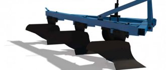
2 Fig.1 Five-furrow mounted plow PLN frame PLZH or PLZH, 2 support wheel PLSH for PLZH or PLU V for PLZH, 3 skimmer PLU, 4 body PLE, 5 body with vertical blade PLU or PLU, 6 brace PLE, 7 stand PLSH Work using a plow equipped with bodies with angles, it is carried out as follows: the angler separates the top layer of soil raised by the formation body, turns it over and places it on the bottom of the furrow. The laid layer is covered with a layer that is lifted and wrapped by the body, as a result of which complete and deep incorporation of weeds and crop residues, as well as the required crumbling of the layer, is achieved. Note. Terms: “right”, “left”, “first”, “second”, “front”, “rear”, found in the text, should be considered as the plow moves. 2.2 Brief information about the design of the plow The five-furrow mounted plow consists of the following main assembly units: frame 1, body 4, skimmer 3, wheel 2, brace 7. The plowing depth is set by the support wheel screw. Depending on the required plowing depth, install the skimmers correctly. The following installation of skimmers is recommended: for plowing with the body to a depth of 20 cm, the stand is fixed on the upper hole to a depth of 22 cm on the second hole to a depth of 25 cm on the third hole to a depth of 27 cm on the fourth hole to a depth of 30 cm on the bottom hole 2.3 Main technical data Technical characteristics of the five-furrow mounted plow PLN 5-35 Indicator Value Productivity for 1 hour of main time when equipped with bodies for working at speeds, ha/h km/h 0.87-1, km/h 1.20-1.60
3 km/h 1.60-2.10 Operating speed during main operations, km/h 5-12 Plowing depth, cm Incl. with subsoilers up to 45 Distance from the supporting plane of the bodies to the bottom plane of the frame, not less, mm Distance between the bodies along the plow path, mm 800±25 Number of bodies, pcs. 5 Body type 620 configuration according to the application Hull working width, mm 350±20 Skimmer working width, mm 230±20 Dry weight of the plow (structural) with a set of working tools for performing the main technological operation, kg see appendix. 2 Labor intensity of assembling the unit man/ h 0.15 Turning radius at the outermost point no more than, m 8.8 Plow dimensions, mm - length width height Transport speed, km/h up to 30 (according to tractor transport speed) Service life, years 8 Warranty service life, years 2 .5 Dimensions of the unit in the transport position (with the T-150 tractor), mm - length width height Ground clearance not less than, mm 250 Operational labor intensity of installation (additional assembly) of the plow at the place of use, person/hour 3. SAFETY REQUIREMENTS When working with the plow it is necessary observe the following rules: 3.1 Do not allow persons who have not read these instructions and have not undergone safety training to assemble and operate the plow. 3.2 Give a signal before the unit starts moving. Drive smoothly, without jerking. 3.3 Before raising or lowering the plow, make sure that no one is nearby. 3.4 It is strictly forbidden to work with a faulty plow; be near the unit while turning; turn the unit; with loose limit chains of the tractor’s mounted system; adjust the plow and tighten the bolts while moving or in the transport position; work with loose fasteners of the working parts; clean the plow while moving or in the transport position; repair the plow; , if it is raised to the transport position or connected to a tractor whose engine is running. 3.5 Before transporting, raise the plow as much as possible and tighten the limit chains of the tractor's mounted system. Make sure that the piston rod does not settle. 3.6 Before replacing the shares, place wooden blocks under the field boards and support wheel. 3.7 Drive plows on public roads only in accordance with the Road Traffic Regulations. 3
4 4. STRUCTURE AND OPERATION OF COMPONENTS OF THE PLOW 4.1 The frame (Fig. 2) is flat, welded and consists of main longitudinal and transverse beams, which are welded together using gussets. 4.2 The body (Fig. 3) consists of a stand to which a shoe with a ploughshare, blade and field board is attached. Thanks to its design, it can be high-speed, cut-out, half-screw, moldless, or cultivated with a subsoiler. Moreover, only the shoe with the ploughshare, blade and sidewall assembled on it is replaced. It is allowed to install a PLU body with an angle without a skimmer on a plow, instead of a PLE body and a PLU skimmer; also, instead of a PLU stand, it is allowed to use a cast stand. When attaching the rack to the shoe, it is permissible not to install the second bolt from above. Rice. 2 Frame PLZH or PLZH reducer PLE, 2 rack PLSH, 3 bolt M24x150 with nut and washer, 4 brace PLE, 5 bolt M24x120 with nut and washer, 6 pin PNChS, 7 strip PLZH with bolt PLU with washer and nut for PLZ, PLU with nut and washer for PLZ
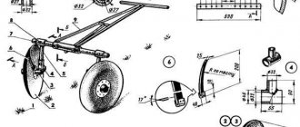
5 Fig. 3 PLE body (PLU with vertical blade) 1 PLU stand blade P bolt M20x90 or M20x80, 4 PLE shoe, 5 field board PNChS ploughshare P vertical knife for PLU The wheel (Fig. 4) is used to set and adjust the depth of plowing. There are marks on the stand for guidance when setting the plowing depth. The wheel consists of a rim with a disk, a stand with a bracket, a hub holder, which includes an axle shaft. 4.4 The skimmer (Fig. 5) is a small body with a cultural working surface. Designed for embedding plant residues. The skimmer consists of a stand, a share, and a blade. 4.5 The hitch consists of racks, braces and reducers. The upper link of the tractor linkage mechanism is attached to the upper holes of the racks. The tractor's lower links are attached to pins secured in the frame lowerers.
6 Fig. 4. PLSH or PLU V wheel 1 PTK stand, 2 PLU nut, 3 PLU screw, 4 — M24x176x150 bracket for PLSH or PYASH for PLU V, 5 PLU holder washer PLU bolt with nut and washer, 8 thrust bolt PYASH, 9 bushing N cuff II.2-60x85-1, 11 bearing 7508, hub PLE B, 13 axle shaft PLU, 14 oiler 1.2, UHL-1, 15 washer 27x6, 16 castle nut PMG with cotter pin, 17 cap N with gasket N with bolts and nuts, 18 PLU or PLU rim, 19 PYASH bolt with nut for PLSCH or PLU for PLU V, 20 PLU handle, 5. ADDITIONAL ASSEMBLY, ADJUSTMENT AND RUN-IN OF THE PRODUCT AT THE SITE OF ITS APPLICATION 5.1 The plow is assembled on wooden stands with a height of mm. 5.2 Unpack the box. Arrange the parts in a convenient order, fastening according to size. 5.3 Sling the frame in the places marked with “chains” and place it on two stands. To stabilize the frame, place wooden spacers between the beams and supports.
7 Install two lowerers 1 (Fig. 2) on the transverse beam of the frame; insert fingers into the lower holes of the lowerers. Assemble the canopy. Connect the brace 4 to the bracket 6 on the frame with a bolt 5. Install the racks 2 on the fingers 6 of the brackets and secure them with nuts. Place spring washers under the nuts. Connect the posts to the brace with bolt 3. Fig. 5 Pre coulter PLU bracket PYASH with nut and washer; 2 holder PNChS A; 3 IF rack; 4 dump P.402; 5 share P In the holes for fastening the PLE housings on the frame (Fig. 3), insert two bolts (M22x85) and a bolt (M22x120). When equipping a plow with PLU, PLU bodies with angle brackets, use bolts for fastening to the frame of the same length M22x85, for the PLU stand, M22x95 for the PLE stand, and for PLU and PLU bodies use M22x95 bolts. Hang the housings and tighten the bolts with locknuts. Attach the housing struts to the stiffener beam with bolts. When installing the vertical body mounting bolt, loosen the bolts that secure the body post to the shoe, place the vertical bolt on top and attach the post to the frame beam, and then tighten the bolts. Install the angle bracket on the body (Fig. 4, 5) to the angle bracket with bolts, spring and flat washers, and nuts. 5.5 Attach the support wheel (Fig. 4) with two brackets 4, spring washers and nuts on the outside of the longitudinal beam. Lower the support wheel to its lowest position (until the screw nut touches the end of the wheel holder). Note. When working in areas not clogged with plant debris, it is recommended to install the wheel on the inside of the longitudinal beam. 5.6 Attach the skimmer to the frame strip (Fig. 5) on the left side in front of the body using holder 2
8 bracket 1, washer and nut. 5.7 When equipping the plow with a vertical knife 7 (Fig. 3), on the last body, attach the vertical knife 7 to the shoe 4 and field board 5 using bolts, spring washers and nuts. Additionally, install a spacer washer between the field board and the body shoe. 6. RULES OF OPERATION AND ADJUSTMENT 6.1 Carefully inspect the plow. Check the fasteners. Lubricate the wheel bearings and rubbing surfaces of parts that do not have grease nipples, the screw and the support wheel stand with grease. 6.2 Depending on the required plowing depth, install the skimmers correctly. 6.3 The distance between the toes of the skimmer shares and the body (along the path of the plow) must be at least 250 mm. The height position of the skimmer is fixed by the cylindrical protrusion of the holder, which fits into one of the five blind holes on the skimmer stand. 6.4 Tighten the skimmer clamps. 6.5 The field edge of the skimmer must overlap the field edge of the body. 6.6 The plow is aggregated with tractors, the hitch system of which is mounted according to a two-point scheme, with a shift from the axis of the T-150 tractor to the right by 60 mm, for the T-150K tractor by 180 mm. 6.7 If the tractor with which the plow is mounted was used to work with trailed implements, it is necessary first of all to dismantle the tractor’s towbar and readjust its hitch system according to a two-point scheme. 6.8 Check whether the tractor linkage braces are set to free movement. 6.9 It is strictly forbidden to work with free movement of the braces! 6.10 If the tractor with which the plow is mounted has a hitch system of a new design, be sure to remove the bolt connecting the cylinder rod lever and the lifting lever. Remove the movable stop from the cylinder rod of the hitch system. Connect the plow to the tractor. Lower the links of the combing system to a height equal to the height of the hitch pins from the soil surface, move the tractor in reverse so that the ball bushings of the lower links of the tractor mounted system are opposite the plow linkage pins. Place the hinges on the linkage pins and lock them with pins. Align the holes of the ball joint of the central link with the holes of the linkage brace, connect with a finger and lock with a pin. Shorten the brace of the right link of the tractor's mounted system as much as possible. Adjust the length of the central link so that the ground clearance under the first body is at least 250 mm. Adjust the length of the limiting chains so that the ends of the lower links have a lateral swing not exceeding 20 mm in each direction. Plow the plow - adjust the plowing depth. Using the marks on the support wheel stand, pre-set the plowing depth equal to approximately 2/3 of the specified depth and begin plowing. During the passage of the first furrow, make sure that the last body plows the soil to the depth set by the support wheel, and the first to a slightly less depth Right the side of the frame should be slightly higher than the left. Adjust the depth of plowing with the last body using the central link. Turn the unit to enter the next furrow only after the plow is fully raised to the transport position. 6.20 To transfer the plow from the transport position to the working position, it is necessary to move the hydraulic system control lever to the position corresponding to the “floating” position of the distributor spool. ensure that the distance from the tractor caterpillar (wheel) to the wall of the furrow is: for the T-150 tractor about 230 mm for the T-150K about 275 mm After passing two or three furrows, you can begin to adjust the plowing depth. Level the frame. It must be parallel to the field surface. All bodies must plow the soil to the same depth. Check the parallelism of the frame in two directions: along the furrow (from the side of the unplowed field) and across (from behind). If the right side of the frame is higher than the left, extend the right link brace of the mounted system.
9 6.26 If the rear part of the frame is higher (lower) than the front, lengthen (shorten) the central link of the tractor's mounted system. Set the required plowing depth with the support wheel and secure the wheel in the holder with a locking bolt. Since the structural placement of the connecting points of the plow and the tractor's mounted system (with a two-point assembly scheme) ensures satisfactory aggregation of the plow with the tractor, practically eliminating the need for special adjustment of the working grip of the plow. Possible deviations from the calculated working grip of the plow of 1.75 m depend only on how accurately the distance from the right caterpillar (wheel) of the tractor to the wall of the furrow is maintained. In the furrow, the plow must move steadily, without distortions to the side or along the course (the frame must be parallel to the soil surface), the working grip must be normal, all bodies must plow the soil to the same depth, plowing must be without under-sloping soil, vegetation must be completed completely After the specified plowing depth is set and a normal working grip is maintained, the quality of plowing is checked according to the following criteria: all bodies after passing leave the same furrow ridges between two passes of the plow are the same as the furrows left by the bodies 6.32 When moving, make sure that in case of oil leakage from the hydraulic system or oil flowing through the piston seals did not reduce ground clearance. This can lead to damage to the plow. Transportation of the plow and its towing can be carried out by tractors with which it is aggregated. For transportation over distances of more than 50 km, it is recommended to use trailer delivery. If you have to plow heavy soils, convert the plow into a four-furrow To convert the plow into a four-hull, you must remove the fifth body with skimmer. 7. MAINTENANCE 7.1 The types and frequency of maintenance are given below. Type of maintenance Maintenance during operational run-in (preparation, implementation, completion) Maintenance Frequency or delivery period for maintenance Engine hours, h Fuel consumed, l, operating time, ha Once after additional assembly at the consumer Shift maintenance (ETM) 10 ha , once every two shifts Maintenance before starting operation for machines of seasonal use Maintenance during storage (between shifts, short-term, long-term) 2 times a year before the start of the spring and autumn arable season 2 times a year after the end of the spring and autumn arable season 7.2 Technical maintenance during operational running-in includes the following operations: When preparing for running-in, clean the working surfaces of the plowshares, dumps, and field boards from paint by washing them off. Apply with a brush or spray. After the paint layer has softened, it is removed with a rag. Check and, if necessary, tighten threaded connections. Check the play in the support wheel bearings by swinging and, if necessary, adjust the axial clearance of the bearings by removing the cap 17 (Fig. 4) and tightening the nut 16 (Fig. ) When removing the support wheel cap 17, check for the presence of lubricant in the bearings. If there is no lubrication, fill the hub with press grease through a grease nipple with a syringe in the amount of 0.15 kg. The labor intensity of maintenance in preparation for running-in is 0.3 people/hour.
10 Maintenance during the operational run-in period: After each pass, check for sticking of the working parts, if there is any, stop the tractor and clean it. The labor intensity of maintenance during the operational run-in period is 0.2 people/hour. Maintenance after completion of the operational run-in: Clean the plow from dust, dirt, plant residues, wash the plow and dry the plow. Visually check the technical condition of the plow components and parts, the tightening of threaded connections, and if necessary, eliminate any identified deviations. The labor intensity of maintenance after the end of the operational run-in is 0.4 people/hour. 7.3 Shift maintenance (ETM) Clean the plow from dust, dirt, and plant residues. Check the completeness of the plow and threaded connections. If necessary, make repairs and tightening. Check the technical condition of wearing parts of the working bodies. If necessary, replace the plowshare blades from the spare parts kit or sharpen them. The labor intensity of ETO is 0.1 person/hour, including the replacement of shares 0.1 person/hour. 7.4 Maintenance before the start of the working season Inspect the plow, check its completeness, the state of wear of parts, working parts, and the tightness of fastening connections. If necessary, carry out work to bring the plow into working condition: replace shares worn to standard, tighten fastening connections. 7.5 Maintenance during storage During storage between shifts (break in use of the plow up to 10 days). Before preparing for storage: Clean the plow from dirt, dust, plant residues, wash and dry. Install the plow on a level area. The labor intensity of maintenance in preparation for inter-shift storage is 0.3 people/hour. No maintenance is carried out during inter-shift storage. When removing from storage: Inspect the plow, check its completeness. In case of incompleteness, install the dismantled parts. The complexity of maintenance when removing from inter-shift storage is 0.3 person/hour. Maintenance during short-term storage (from 10 days to two months) includes the following operations: When preparing for storage: clean from dust, dirt, plant residues, wash and dry, cover with a preservative composition of unpainted surfaces of working parts (shares, moldboards, field boards) install the plow on a level area Labor intensity of maintenance in preparation for short-term storage 0.5 person/hour Do not carry out maintenance during the storage period When removing from storage: inspect the plow, check its completeness. In case of incompleteness, install the dismantled parts and remove the preservative composition from the working parts with a rag. The labor intensity of maintenance during short-term storage is 0.15 person/hour. Maintenance during long-term storage includes the following operations: When preparing for storage: clean the plow from dust, dirt, plant residues, wash and dry it, deliver the plow to the storage location, check the technical condition of all assemblies, parts, fastening connections
11, if necessary, replace worn parts of the working parts, tighten the fastening joints, carry out repairs, remove the hubs of the support wheels from the wheels, open the caps, rinse the internal parts of old grease and install the hubs on the wheel disks, check by lateral swing of the wheel for clearance in the bearings. To eliminate the gaps, tighten the castle nut 16 (Fig. 4) as far as possible, while turning the wheel, then loosen the nut on one or two slots in the crown until one of the slots coincides with the hole for the cotter pin in the axle shaft. If, when fully tightened, the hole for the cotter pin extends beyond the end of the castle nut, it is necessary to place an additional flat washer under the nut, fill the hub with fresh lubricant, press grease in an amount of at least 0.15 kg through an oiler, clean the areas susceptible to corrosion, and touch up the damaged areas with paint . Coat the unpainted surfaces of the working parts with a preservative compound (see lubrication table). During storage: Check the condition of the plow monthly when stored under a canopy and in an open area, after two months in enclosed spaces; The plow must not come into contact with sewage and must not be rusty. If found, remove it. Labor intensity of maintenance during storage is 0.2 people/hour When removing from storage: Clean the plow from the preservative composition with a rag. Labor intensity of maintenance when removed from storage is 0.1 person/hour 8. STORAGE RULES 8.1 Store the plow indoors or under a canopy. Storage is allowed in open specially equipped areas with mandatory conservation, sealing and removal of components requiring warehousing. 8.2 Place the plow for inter-shift and short-term storage immediately after completion of work, and for long-term storage no later than 10 days after completion of work. 8.3 Carry out maintenance during storage when preparing the plow for storage, during storage and when removing it from storage to prepare the plow for operation. when preparing the plow for storage, assess the technical condition, determine the residual life of the components during storage, check the condition of the plow indoors at least once every two months, and in open areas and under a canopy monthly. After heavy rains, winds and snow drifts, check and eliminate any deficiencies found immediately. 8.4 Carry out work related to the maintenance of the plow during storage under the supervision of the person responsible for storage. 8.5 Be sure to record the placement of the plow for long-term storage and its removal from long-term storage in the log book for placing the machines into storage and putting them into operation, indicating the technical condition and completeness of the plow. 8.6 Shelf life without re-preservation is 1 year. 8.7 Option of anti-corrosion protection VZ-4 GOST POSSIBLE MALFUNCTIONS AND METHODS OF THEIR ELIMINATION POSSIBLE MALFUNCTIONS AND METHODS OF THEIR ELIMINATION Malfunction and its external manifestation The first body plows deeper (shallower) than the other bodies, the ridge left by the first body is higher (lower) than the neighboring ones. The last body plows deeper (smaller) than the other bodies; the ridge left by the last body is higher (lower) than the neighboring ones. The grip of the first body is greater (less than) than the grip of the remaining bodies; the furrows between two passes are not the same as the furrows left by the bodies; Elimination method: Shorten (lengthen) the right brace of the mounted linkage tractor system Shorten (lengthen) the upper link of the tractor mounted system Drive the unit so that the right caterpillar goes closer (further) relative to the wall of the furrow
12 The disc coulter is installed incorrectly; the furrow wall is destroyed. The knife is too low or has become dull. Stubble residues are collected in front of the disc coulter. The knife does not cut the sod layer. Stubble residues are collected behind the disc coulter, clinging to the skimmer stand. Move the knife away from the skimmer edge. Adjust it to its height Raise the disc blade, sharpen the blade Lower the disc blade and move it forward Fig. 6 Lubrication diagram LUBRICATION TABLE pos. on the lubrication diagram Name of lubrication points Name, brand, designation of the standard art for lubricants and liquids Lubrication during operation at temperatures From -40 C to +5 C From +5 C to +50 C Refilling during operation Lubrication at storage Number of lubrication points Frequency of lubrication 1 Working surfaces of shares, dumps, chest of dumps, sidewalls Solid oil GOST, solid oil GOST Safety composition PP 95/5 GOST At the beginning and end of the season. When storing 2 Support wheel screw Solidol GOST Solidol GOST At the beginning and end of the season. When operating over 100 hectares 3 Wheel hub Solid oil GOST Gun lubricant GOST T At the beginning and end of the season. When storing Appendix 1 Appendix 1. List of bearings used on the plow Bearing type Catalog number Installation location Number of bearings
13 Roller conical single row Per unit Per product 7508 GOST T Wheel 2 2 Appendix 2 Plow brand according to specifications Speed up to 12 km/h Appendix 2. Types of bodies and working speeds Type of bodies and working speed Cultural up to 9 km/h Cultural speed o 7 km/h Semi-screw 7-9 km/h Cut-out up to o 7 km/h Subsoiler body up to o 7 km/h Plow weight, kg PLN PLN PLN PLN PLN PLN
Cases of plow malfunction
Among the problems of a mechanical nature, the following defects should be listed: cases of warping and loss of cutting properties by the blades of plowshares and disc knives, rounding of the toe of the plowshare, reduction in the width of the plowshares, wear of the chest and wing of the blade (typical of high-speed bodies), as well as critical wear of the lower part of the field board .
Problems that appear during plow operation usually have the following symptoms:
- Strong swing of the plow in the transport position.
- The travel of the front and rear bodies is different in depth.
- A noticeable joint between adjacent plow passes.
- Systematic drift of the plow in any direction (fields or furrows).
- Crop residues clog the breast edge, disc coulter and skimmer shank.
Another common operational problem is excessive depth of the mounted plow.
The reasons for their occurrence
The listed cases of loss of the required sharpness of cutting surfaces, as well as changes in their geometry, are usually associated with natural mechanical wear, or are a consequence of impact with hard objects. The problem of different depths of travel of the bodies is most often a consequence of incorrect installation of the frame in the longitudinal direction, and the plow drifting to the side is due to its incorrect position in the horizontal plane.
The appearance of a visible joint between the passes indicates that the working grip does not correspond to the nominal value, and the crumbling wall of the furrow indicates incorrect installation of the disc knife.
All problems associated with crop residues that interfere with work are usually the result of dull or too deeply buried knives. Excessive deepening of a mounted plow most often occurs due to the installation of the distributor lever in the neutral position, and its swinging in the transport position is due to the adjustment of the length of the limiting chains of the hitch device.