3. SAFETY REQUIREMENTS
Only persons who are well instructed and have mastered the design and operating rules are allowed to work with the plow.
When working with a plow, the following rules must be observed:
- before starting to move, as well as before raising and lowering the plow, the tractor driver must make sure that these actions are safe for others and give a signal
- When making repairs or adjustments, it is not allowed to be under the plow if it is coupled to the tractor
- do not sit on the frame while the plow is working or transporting it
- Before the unit starts moving, a signal must be given
It is strictly prohibited:
- work with a faulty plow
- stay near the machine while turning
- turn the machine when the limit chains of the tractor's mounted system are loosened
- adjust the plow and tighten the bolts while moving or in transport position
- clean the plow while moving or in transport position
- repair the plow if it is raised to the transport position or connected to a tractor whose engine is running.
Before transportation, the limit chains of the tractor's mounted system must be tightened and the plow raised as much as possible.
It is necessary to ensure that the piston rod does not settle.
Before replacing the plowshares, wooden blocks must be placed under the field boards and support wheel.
It is strictly forbidden to work with loose fasteners of working parts.
Driving of mobile agricultural vehicles on public roads is carried out in accordance with the Traffic Rules.
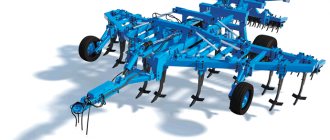
4. STRUCTURE AND OPERATION OF COMPONENTS OF THE PLOW
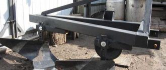
Rice. 2 Frame PLE 04.000-02
1 – bracket (lower) PLE 04.319, 2 – rack PLSH 04.514, 3 – bolt M24x150, 4 – brace PLE 04.200-02, 5 – bolt M24x120, 6 – pin PNChS 04.612, 7 – bolt PLU 04.706-02
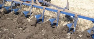
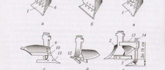
Rice. 3 Housing PLE 21.000-03 (PLU 51.000-03 with vertical blade)
1 – stand PLU 91.200-01 2 – blade P-401 3 – bolt M20x90 or M20x80, 4 – shoe PLE 01100-02, 5 – field board PNChS-502 6 – plowshare P-702 7 – vertical knife for PLU 51.000
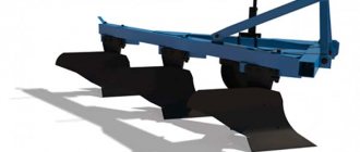
4.1 The frame PLE 04.000-01 (Fig. 2) is flat, welded and consists of beams (main, transverse and transverse), which are welded together using gussets.
4.2 The body (Fig. 3) consists of a stand, a shoe, a ploughshare, a blade, and a field board.
The body, due to its design, can be high-speed, cut-out, semi-screw, non-moldboard, cultural with a subsoiler, and only the shoe is replaced, with the blade and field board assembled on it with a ploughshare. This significantly expands the scope of application of the plow.
4.3 The skimmer PLU 02.000 (Fig. 4) is a small body with a cultural working surface. Designed for embedding plant residues.
The skimmer consists of a stand 3, a share 5, a blade 4.
Setting the skimmer to the required plowing depth is fixed by the protrusion of the holder 2, inserted into one of the holes of the stand 3.
Rice. 4 Skimmer PLU 02.000
1 – bracket PYASH.02.107-02 with a nut and washer; 2 – holder PNChS.02.302A; 3 – rack PCh.02.503; 4 – dump P.402; 5 – ploughshare P-703
4.4 The PLSH wheel 05.000-04 (Fig. 5) is used to set and adjust the plowing depth. There are marks on the stand for orientation when setting the plowing depth, according to the position of the mark at the level of the upper edge of the holder. The wheel consists of a rim with a disk, a stand 1 with a bracket, a holder 5 and a hub 11, which includes an axle shaft 14.
Fig 5. Wheel PLSH 05.000-03 or PLU 05.000V
1 – stand PTK 17.320, 2 – nut PLU 05.616, 3 – screw PLU 06.618, 4 – bracket M24x176x150 for PLShCH 05.000-03 or PYASH 02.107-05 for PLU 05.000V, 5 – holder PLU 05.315 6 – shai ba 20.02 7 – PLU bolt 05.154 with nut and washer, 8 – thrust bolt PYASH 30.103, 9 – bushing N 047.05.0009 10 – cuff II.2-60x85-1, 11 – bearing 7508, hub PLE 06.147B, 13 – axle shaft PLU 06.631, 14 – oiler 1.2, UHL-1, 15 – washer 27x6, 16 – castle nut PMG 05.632 with cotter pin, 17 – cap N047.05.0001 with gasket N047.05.011 with bolts and nuts, 18 – rim PLU 06.500 or PLU 06.510, 19 – bolt PYASH 30.103 -03 with nut for PLSCH 05.000-03 or PLU 05.349 for PLU 05.000V, 20 – handle PLU 05.601,
It is allowed to install a vertical knife on the last body of the plow.
5. ADDITIONAL ASSEMBLY, ADJUSTMENT AND RUN-IN OF THE PRODUCT AT THE SITE OF ITS APPLICATION.
5.1 The plow is shipped from the factory assembled into assembly units. Assembled on wooden stands 65-70 cm high.
Arrange the parts in a convenient order, and the fastening parts according to size.
5.2 Lock the frame and place it on two stands. To stabilize the frame, place wooden spacers between the beams and supports.
Install the brackets (lowers) on the front frame beam and secure them with bolts, strips, nuts and spring washers. Remove the two racks and hinges attached to the bracket on the frame. Install fingers 6 into brackets 1 (Fig. 2) on the front frame beam. Assemble the hitch. Connect the brace 4 to the bracket on the frame with a bolt 5. Install the racks 2 on the pins 6 of the brackets 1 and secure them with nuts. Place spring washers under the nuts. Connect the posts to the brace with bolt 3.
5.3 Insert two bolts (M22x95) and one bolt (M22x130) into the holes for fastening PLE 21.000 housings on the frame (Fig. 2).
When equipping the plow with PLU 51.000 bodies, use bolts for fastening to the frame of the same length M22x95.
To install the vertical bolt for fastening the housings, it is necessary to loosen the bolts securing the housing strut to the shoe, insert the vertical bolt from above, secure the strut to the frame beam and then tighten all the bolts.
Hang the housings and tighten the bolts with nuts and locknuts.
Attach the housing struts to the stiffener beam with bolts, first place them under nuts, strips and spring washers.
5.4 Attach the support wheel (Fig. 5) with bracket 4, spring washers and nuts on the outside of the longitudinal beam.
5.5 Lower the support wheel to its extreme position (until the screw nut touches the end of the wheel holder).
5.6 When equipping the plow with a vertical knife 7 (Fig. 3), on the last body, attach the vertical knife to the shoe and field board 5 using bolts, spring washers and nuts.
Additionally, install a spacer washer between the field board and the shoe.
Screw locking bolt 19 (Fig. 5) with a nut into the hole in the holder. Tighten the clamp as far as it will go. Remove the stands.
Note. When working in areas not clogged with plant debris, it is recommended to install the support wheel on the inside of the longitudinal beam.
If the plow is equipped with skimmers, then attach the skimmer to the frame strip on the left side in front of the body with holder 2, bracket 1 and nuts (Fig. 4). Place spring washers under the nuts on the brackets. Do not overtighten the clamp.
6. RULES OF OPERATION AND ADJUSTMENT
6.1 Carefully inspect the plow. Check the fasteners, lubricate the wheel bearings and the rubbing surfaces of parts that do not have oil nipples, the screw, and the support wheel stand with grease "F".
6.2 Depending on the required plowing depth, install the skimmers correctly.
6.3 The distance between the toes of the skimmer shares and the body (along the course of the plow) must be at least 250 mm. The height position of the skimmer is fixed by a cylindrical protrusion of the holder, which fits into one of the five holes on the skimmer stand.
6.4 Tighten the skimmer mounting brackets.
6.5 The field edge of the skimmer must overlap the field edge of the body.
6.6 The plow is mounted on tractors whose hitch system is mounted only in a two-point manner with a 60 mm offset from the tractor axis.
6.7 If the tractor with which the plow is assembled was used to work with trailed implements, it is necessary first of all to dismantle the tractor’s trailing device and readjust its hitch system according to the two-point scheme (see “Tractor Operation Manual”, section “Readjustment of the mechanism for hanging implements in different working conditions").
6.8 Install the suspension linkage braces to a length of 670 mm (between the axes of the outer hinges)
6.9 Check whether the tractor linkage braces are set to free movement.
It is strictly prohibited to work when the braces move freely!
6.10 If the tractor with which the plow is coupled has a new design linkage system, be sure to remove the bolt connecting the cylinder rod lever and the lifting lever.
6.11 Connect the plow to the tractor. Lower the links of the mounted system to a height equal to the height of the hitch pins from the soil surface, drive the tractor in reverse so that the ball bushings of the lower links of the tractor mounted system are against the pins of the plow linkage.
6.12 Place the hinges on the hinge pins and secure them with pins. Align the hole of the ball joint of the central link with the holes of the linkage brace, connect it with a finger and lock it with a pin.
6.13 Shorten the right link brace of the tractor's mounted system as much as possible. Adjust the length of the central link so that the ground clearance under the first body is at least 250 mm.
6.14 Adjust the length of the limit chains so that the ends of the lower links have a lateral swing not exceeding 20 mm in each direction.
6.15 Plow the plow - adjust the plowing depth. Using the marks on the support wheel stand, pre-set the plowing depth to approximately 2/3 of the specified depth and begin plowing.
6.16 During the passage of the first furrow, make sure that the last body plows the soil to the depth set by the support wheel, and the first one to a slightly shallower depth.
6.17 The right side of the frame should be slightly higher than the left.
Adjust the plowing depth with the last body using the central link.
6.18 Only turn the implement into the next furrow after the plow is fully raised to the transport position.
6.19 To transfer the plow from the transport position to the working position, it is necessary to move the hydraulic system lever to the position corresponding to the floating position of the distributor spool.
6.20 After passing two or three furrows, you can begin to adjust the plowing depth.
6.21 Level the frame. It should be parallel to the soil surface. All bodies must plow the soil to the same depth.
6.22 Check the parallelism of the frame in two directions: along the furrow (from the side of the unplowed field) and across (from behind).
6.23 If the rear part of the frame is higher or lower than the front, lengthen or shorten the central link of the tractor's hitch system.
6.24 Set the support wheel to the required plowing depth and secure the wheel in the holder with the locking bolt.
6.25 Since the constructive placement of the connecting points of the plow and the tractor’s mounted system (with a two-point assembly scheme) ensures satisfactory aggregation of the plow with the tractor, there is practically no need for special adjustment of the working grip of the plow.
6.26 Possible deviations from the calculated working grip of the plow of 140 cm depend only on how accurately the distance from the right tractor caterpillar to the wall of the furrow is maintained. It should be 6-10 cm.
6.27 In the furrow, the plow must move steadily, without distortions to the side or along the course (the frame must be parallel to the soil surface), the working grip must be normal: all bodies must plow the soil to the same depth, plowing must be without undersoil.
6.28 After the specified plowing depth has been established and normal working grip is maintained, the quality of plowing is checked according to the following criteria:
- all hulls leave identical ridges after passage
- the furrows between two passes of the plow are the same as the furrows left by the bodies
6.30 When moving, make sure that in the event of oil leakage from the hydraulic system or oil flowing through the piston seals, the ground clearance is not reduced. This may lead to damage to the plow.
7. MAINTENANCE
7.1 Types and frequency of maintenance are given below.
Installation of working tools for moldboard plowing of plows PLN 3-35, PLN 4-35
Installation of skimmer plow PLN 3-35
Horizontally, the skimmer is installed in front of the main body at a distance equal to the working width of the main body (30-35cm). Its height is set so that it removes the top layer of soil to a depth of 7-12 cm. It is recommended to install the skimmer depending on the plowing depth as follows:
- for plowing with the plow body to a depth of 20 cm, we fix the stand on the upper hole;
- for plowing to a depth of 22 cm - on the 2nd hole;
- for plowing to a depth of 25 cm - on the 3rd hole;
- for plowing to a depth of 27 cm - on the 4th hole;
- for plowing to a depth of 30 cm - at the lowest hole.
The field edges of the skimmer and the body must be located in the same vertical plane (deviation of the skimmer edge towards the field is allowed up to 1-2 cm).
Installation of the disc blade of the plow PLN 3-35, PLN 4-35
The disc blade is installed so that the center of the disc coincides vertically with the toe of the skimmer share or is moved forward by a distance of up to 130 mm. The blade of the disk should be 2-3 cm below the toe of the skimmer share. The gap between the plane of rotation of the disk and the field edge of the skimmer should be 1-3 cm.