List of links
- NPAOP 0.00-1.01-07. Rules for the proper and safe operation of vanity taps // Ref. By order of the State Committee of Ukraine for industrial security, protection of goods and agricultural products, 06/18/2007 No. 132.
- Stroy-Tekhnika.ru: Construction machines and equipment, reference book. – https://stroy-technics.ru.
- Oksanich L.V. A training manual for slingers on the safe performance of work with lifting machines // Consulting project “EAM”. – https://eam.su/category/materialy/obshhetexnicheskie-svedeniya/uchebnoe-posobie-dlya-stropalshhikov-po-bezopasnomu-proizvodstvu-rabot-gruzopodyomnymi-mashinami.
A smooth, unthreaded part is placed between the grooved sections of the drum. The ends of the rope are in most cases secured to the edges of the drum. The branches of the rope descending from the drum are brought to the outer blocks of the hook suspension, and when the rope is wound onto the drum, it is wound from the edges to the middle. In heavy-duty cranes with a large pulley ratio and, therefore, a large number of blocks on the suspension, the drums require long unthreaded sections, which leads to an increase in the length of the drum and the size of the lifting mechanism.
To eliminate this inconvenience, a rope winding scheme is used, in which its ends are fixed at the edges of the middle smooth part of the drum and brought to the internal blocks of the hook suspension. When lifting a load, the rope is wound in the direction from the middle to the edges of the drum. But even in this case, you can make winding according to the above scheme, reduce the number of branches of the pulley with a corresponding increase in the diameter of the rope. The rope capacity of the drum must be such that at the lowest possible position of the load-handling element on the drum, at least 1.5 turns of the rope remain wound, not counting the turns located under the clamping device.
For grab cranes, during the operation of which jerks and weakening of the rope are possible, with a single-layer winding of the rope, the drums must have a groove with a depth of at least 0.5 of the diameter of the rope or be equipped with a device that ensures correct laying of the rope on the drum. The most convenient designs for fastening the rope to the drum are using a wedge and locking bolts, clamps and several turns of rope wound around the drum hub, and clamping strips and bolts (Fig. 2.30).
The loop at the end of the rope when attaching it to the drum, as well as the loop of the sling associated with rings, hooks and other parts, must be made using a thimble by braiding the free end of the rope, installing clamps or other proven methods according to approved standards.
The end of the rope on the drum can also be attached to a forged steel, stamped, cast conical bushing using a wedge or filling with a low-melting alloy. Welded bushings are not permitted. The bushing bodies and wedges should not have sharp edges on which the rope can rub.
Rice. 2.30. Fastening the rope to the drum: a - using a wedge; b - clamping strips; c - with a molar clamp
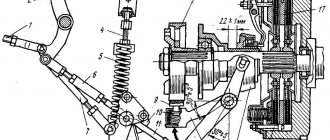
Rope drums of cranes are often installed on rotating and less often on fixed axles. In the first case, the drum is bolted to a gear mounted on a key and rotates with it and the axis (Fig. 2.31). Ease of maintenance, lubrication and repair are the main advantages of the structures.
Rice. 2.31. Rope drum
For overhead cranes, the coefficient e has the following values: for light duty operation, e - 20; with average e - 25; for severe E - 30; with very heavy e - 35. It is allowed to take the diameter of the drum less than that determined by formula (2.3) by 15%, and the diameter of the equalizing block - by 20%.
Depending on the operating conditions of the crane, the blocks are made of cast, cast iron or steel. In modern cranes, blocks rotate on rolling bearings. It is not allowed to use blocks with defects on cranes - broken sides, cracks, worn-out bushings, etc.
There are several ways to attach block hangers to a drum, depending on the number of rope branches. With four branches (Fig. 2.32, a), the rope is thrown over an equalizing block, both halves of the rope are equalized, and then one end is passed through the suspension block and secured to the drum. The second end of the rope is passed through the second suspension block and is also secured to the drum.
With six branches of the pulley block (Fig. 2.32, b), the end of the rope is passed through the equalizing block located between the two lower working blocks of the pulley block. After this, the ends of the ropes are thrown over the upper fixed blocks, passed through the lower pulley blocks and secured to the drum.
With ten branches (Fig. 2.32, c), the rope suspension is performed as follows: the rope is passed through a leveling block located at the bottom between the movable blocks of the pulley block; the ends are thrown over the upper fixed blocks, then under the movable blocks of the pulley block, through the second upper blocks, then through the lower movable blocks of the pulley block and the ends of the rope are secured to the drum.
The designs of equalization blocks are shown in Fig. 2.33. The leveling block rotates only when the branches of the new rope are aligned. When the branches are aligned, it does not rotate or rotates almost imperceptibly - by a fraction of a turn.
Rice. 2.32. Hanging chain hoists to the drums 1 - small drive gear; 2 - drum gear; 3 - drum; 4 thorns; 7 – movable blocks; 9 — upper block; 9 - hook
Rice. 2.33. Leveling blocks
However, you cannot do without it; you cannot tightly fasten the rope passing through the equalizing block. Unevenness in the stretch of rope branches that is imperceptible to the eye will lead to a sharp unevenness of the load on the rope branches, which, in turn, can cause premature wear and sometimes even breakage. In this regard, it is necessary to strictly monitor the fastening of the equalization block. The loss of the leveling block from the supports leads to the fall of the hook to the workshop floor or to the ground.
Classification of overhead cranes
Bridge lifting mechanisms (lifting mechanisms) have a broad classification.
Cranes for general industrial purposes are equipped with a load hook. Special lifting and transport mechanisms are equipped with a highly specialized grip: container grip, magnet, grab.
The type of crane support can be suspended or support. Suspended mechanisms are considered to be those suspended on the edges of I-beams, which in turn are fixed in the upper part of the building. The running wheels rest on the inside of the beam and move along them. The support cranes move on rails mounted on crane beams, which are also fixed in the upper part of the workshop.
Based on the number of load-bearing beams, GPMs are divided into single-beam and double-beam.
- Single beam. Load capacity less than 10 tons, used in small enterprises.
- Double beam. The load capacity is above 8 tons, the scope of application is wide: mechanical engineering, mining, metallurgy. The span length can reach 60 meters. If necessary, it is possible to install an auxiliary cargo mechanism.
The drive can be manual or electric.
- Manual - for operation it is necessary to set the winch in motion.
- Electric - move without the help of an operator, operate from the network.
The overwhelming majority are powerful cranes with electric hoists, as well as those operating as an electric winch.
Fig 1. Diagram of an overhead crane
Types of cargo drums and their characteristics
To reduce friction and tension when it comes into contact with the rope, the cargo drum is equipped with threading. It is necessary for neat and even laying of the rope. Based on the direction of cable laying required, the drums are divided into left and right.
According to the method of rope winding, cargo drums are divided into:
- drums with multilayer rope winding;
- drums with single-layer rope winding.
Multilayer cable winding
With this method of cable winding, the surface of the drum has a polished coating, and it is fenced on both sides with the help of sides. According to established standards, each side must be located from the cable laid on it at a distance equal to two of its diameters. Drums with rope winding in several layers are used to reduce dimensions. The disadvantage of this method is the rapid wear of the rope, which makes it unsuitable for further use.
Single layer cable winding
This method of winding a cable implies the presence of threaded screw grooves on the drum, which help to increase the area of contact with the surface of the drum. The grooves ensure proper placement of the rope on the drum surface and avoid friction between adjacent turns. Winding a rope in one layer is more durable and has a high level of strength, and is used to increase the service life of the product.
Additional equipment: safety and efficiency of overhead cranes
Equipping an overhead crane with additional electronic and mechanical devices significantly increases the operating efficiency of the equipment, the safety of work, improves controllability, and also helps prevent rapid wear of components and mechanisms.
- Crane scales are necessary to determine the exact weight of cargo during loading and unloading operations. Attached to the load-handling mechanism.
- Load limiters - prevent equipment from being overloaded. Installed on the rope of the lifting mechanism. Lifting of loads is switched off if their permissible weight is exceeded.
- Radio control and floor control are alternative options for operating the crane from the cab. Installation of radio control (control from the floor) ensures safe work, greater visibility for the operator, and more accurate positioning of the load. Transferring an overhead crane from control from the cabin to control from the floor provides a number of financial advantages, such as savings on personnel, savings on mandatory certification of crane operators, and savings on industrial safety expertise.
- Frequency converters are connected to motors to ensure smoother running of overhead crane units, avoid jerking and excessive swinging of loads, and prevent overloads in the operation of electric motors. This increases engine life and reduces equipment repair and maintenance costs.
Trolley device
On the rigid trolley there are:
- Lifting and moving devices.
- Current distribution unit.
- A safety mechanism that limits the maximum possible weight and lifting height of a load.
If the weight is lifted more than 10% beyond the capabilities of the crane mechanism, the lifting of the load will stop. Also, when approaching the edge of the rail track, the trolley automatically stops. If the brakes fail, the trolley is stopped by buffers.
Overhead crane installation diagram
To install lifting and transport equipment, a special installation diagram is developed, showing the principle of connecting the units and regulating the maximum permissible limits.
The group of structures for the installation of bridge-type lifting equipment has the following form: half-bridges, main and auxiliary cargo trolleys, balancers, cabin, safety systems.
Installation of crane equipment must be carried out while maintaining the distances from load-bearing structures to load-bearing walls and equipment. After completion of the installation work, all dimensions must be carefully checked in full size - only this can ensure the full and safe operation of the crane equipment.
Rice. 3. Drawing of an overhead crane indicating the dimensions of the approach
Overhead cranes are reliable lifting devices that are used everywhere. Their only drawback is their large weight and static nature, however, within the premises they are capable of picking up cargo from any hard-to-reach point.
Assembly technology of standard components and mechanisms. 3. Assembling cargo drums
Separate assembly units of the drum (subgroups of the first order) are a gear hub assembled with a cover, a shaft assembled with an idle hub and rolling bearings, and an oil pipe. The general assembly of the drum is carried out on prismatic roller supports. The mounting bolts for the hubs are inserted from the inside of the drum and pressed in with a suspension hydraulic clamp. The position of the gear and idler hubs based on the pitch of the bolts is determined by the markings made during processing, and they are marked again during assembly. The shaft assembly with the idler hub is inserted into the drum and the hole of the gear hub using a special support. A wrench is used to tighten the studs and nuts that secure the planks. In large-scale production of drums, assembly mechanization tools are widely used. At one of the factories, a special assembly stand with a tilter is successfully used. The main unit of the stand is a frame that rotates around a horizontal axis with fixation every 90°. Two drums are installed in the frame on prismatic supports and between two end stops. Pullers with hydraulic cylinders for installing and removing drums are mounted on the installation portal. To do this, the puller is inserted into the drum hub, after which its grips are moved apart. On the same portal, a wrench and a hydraulic clamp for pressing bolts are installed on separate consoles. These devices are used when making assembly transitions from the end sides of the drum when they occupy a vertical position. The bearings are pressed into place by hydraulic cylinders located on both sides and driven when the axes of the drums are horizontal. The tilter not only reduces the main time of the assembly operation, but also minimizes the auxiliary time, which is usually long when assembling such large units. All auxiliary movements on the stand are mechanized.
To clarify the characteristics you require and receive a questionnaire, contact our sales service by phone at
8-937-858-01-05 or by email This email address is being protected from spambots. You must have JavaScript enabled to view it. .
See also:
- Catalog of cranes.
- Beam cranes: production catalogue.
- Overhead cranes: production catalogue.
- Gantry cranes cranes: production catalogue.
- Console cranes: production catalogue.
- Catalog of electrification systems.
- official representative office of the crane plant in Ufa.