The rear axle housing is rigidly attached to the brackets using a yoke and four bolts on each side.
Brackets connected to the coupling angle with bolts form the basis for mounting the PTO gearbox.
A double hinge consists of a hinge body, a vertical hinge axle, a horizontal hinge tube and a yoke.
The hinge body is a cast steel pipe with two massive I-section protrusions located in a vertical plane. Steel bushings are pressed into the holes at the ends of the protrusions. The projections of the hinge body fit into the eyes of the rear beam of the frame and are connected by axles, forming a vertical hinge of the frame. The axles of the vertical hinge are kept from falling out by transverse bars, which fit into the grooves of the rear beam of the frame and are secured with two bolts each. The bar is welded to the end of the axle and additionally secured with a bolt.
On tractors produced since August 1973, to increase the reliability and maintainability of the frame, steel bushings were pressed into the holes of the hinge support eyes and lubricant was introduced into the vertical hinge axes. Lubricant is supplied to the rubbing surfaces of the vertical hinge through the longitudinal and transverse channels of the axle through a lubricant installed at the end of the axle. Two diametrically located flats on the axis form a cavity for lubrication. To prevent wear of the body parts of the frame hinge, washers are installed under the rubbing surfaces of the vertical hinge. The edges of the washers have bevels that secure the washers from turning. The hinge body is connected to the rear hinge support using a horizontal hinge pipe, one end of which is rigidly clamped between the yoke and the rear support, and the other rotates freely in steel bushings pressed into the hinge body. The yoke is secured with a pin and attached to the rear hinge support with three studs on each side.
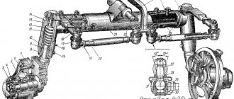
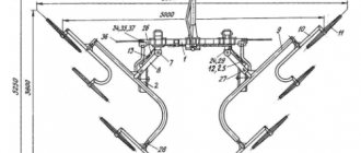
Rice. 1. Frame: 1 — front beam; 2 — towing hook; 3 and 18 — front side members; 4 and 19 — spring brackets; 5 — locking bracket; 6 and 20 — shock absorber bracket: 7 and 21 — rear spring brackets; 8 — pads; 9 - scarf; 10— stud: 11— nut; 12, 15 — yoke; 13 and 31 — rear side members; 14 and 30 — rear axle brackets; 16 - bolt; 17 and 32 — brackets for the upper shaft of the rear linkage; 22 — brackets; 23— rear beam; 24 — follower rod bracket; 25 — rotating bracket; 26 — oiler; 27 — transverse beam; 28 — cylinder axis; 29 — axle flange; 33 and 35—brackets; 34 — clamping angle.
Rice. 2. Double hinge: 1 - rear beam; 2 and 6 — bushings; 3 — washer; 4 - bushing; 5 — vertical hinge axis; 7—bar; 8 and 9 - bolts; 10 — hinge body; 11 — front oil seal; 12 - collar; 13 and 14 — bushings; 15 — rear oil seal; 16 — clamp; 17 — thrust washer; 18 — rear support; 19 - half ring; 20 - pin; 21 — yoke; 22 — horizontal hinge pipe; 23 — adjusting washer; 24 - ring; 25 — adjusting gasket; 26 - bolt; 27—clip; 28—oiler.
The ring is welded into the pipe and secured with four pins and is intended for fastening the intermediate support of the rear axle cardan drive.
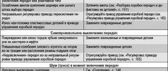
Frame care. After running in the tractor and during maintenance No. 2, it is necessary to check the tightness of the horizontal hinge yoke fastening nuts and the rear axle yoke fastening bolts. During seasonal maintenance, it is necessary to lubricate the horizontal hinge pipe through a grease nipple.
During work, it is necessary to clean the frame from dirt, check the condition of the rivet and bolt connections from hammer blows (the rivet should not tremble, move along the axis and rotate), monitor the condition of the horizontal hinge seal, the vertical hinge washers and the locking of the vertical hinge axes.
If the rear felt seal is worn, it is necessary to tighten the clamp, and if the front one is worn, remove the required number of gaskets.
When carrying out installation and demolition work related to lifting the frame or the tractor as a whole, the jack must be installed in places marked with paint with the letters “DK” on the vertical flanges of the side members.
Rice. 3. Suspension:
Tractor frames - frame frame, semi-frame frame, frameless frame
The frame is the supporting part of the tractor, its base. It is loaded with the weight of the units placed on it and takes up dynamic loads when the tractor starts from a standstill, accelerates, overcomes uneven paths, and turns. It must have high rigidity and strength, and work without replacement for the entire service life of the tractor.
There are three types of frames: frame, semi-frame, frameless.
The frame frame is formed by the main longitudinal beams (spars).
which are connected by cross members that act as supports for individual units. Such a frame has good rigidity and strength, makes it easier to access individual mechanisms and replace them, but has more weight than a semi-frame one.
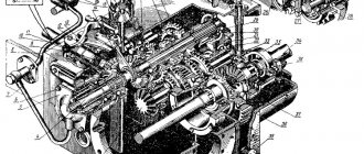
Rice. 2.10. Layouts of crawler forestry tractors:
a - general purpose, 6 - swamp, I - pusher; 2 — cabin; 3 • engine, 4 — winch; 5 - gearbox. 6. 8 — cardan shafts of the PTO drive, 7 — body; 9 — PTO gearbox, 10 — hitch, II — drive wheel, 12 — cardan shafts
b) 12
The articulated frame (Fig. 2.11) consists of two semi-frames: front / and rear 4, connected to each other by a hinge device i.
The hinge device consists of two hinges - vertical 2 and horizontal 5. The vertical hinge allows the semi-frames I w 4 to rotate relative to each other at an angle of up to 35°, thereby ensuring rotation of the tractor. The horizontal hinge, allowing the semi-frames to rotate relative to each other at an angle of up to 16°, serves to adapt the wheels to the topography of the road and relieve the frame from additional torsional loads when the tractor moves over rough terrain.
The frame frame is used on tracked agricultural, industrial and forestry tractors of domestic and foreign production and on wheeled tractors with an articulated frame (T-150K and K-70I/701M).
To install tractor units on the frame, central brackets and treated platforms are provided.
Let's consider the design of the frame frame of the DT-75M tracked agricultural tractor (Fig. 2.12).
FIGURE 2.11. Articulated frame of a wheeled tractor
The main elements of the frame are two longitudinal spars 5, which are interconnected by transverse beams P. The spars have brackets designed for mounting the radiator and the front hitch of agricultural implements (bracket 3), the upper axis of the support rollers and agricultural machines with front and side hitches (bracket 7 ), supporting rollers and struts of the linkage mechanism (bracket 8), and rear bracket 9. Pads 6 are welded to the side members for attaching engine mounts. In front of the frame there is a cast beam 2 with a bumper 1. Towing hooks 12 are welded to the side members in the front part, and support brackets 13 for the tension mechanisms of the caterpillar mover are attached to the side walls. The frame side members have holes for installing supports for the 4 axles of the guide wheels. The trunnions 10 of the carriages are inserted into the bored holes of the hollow heads of the transverse bars 11.
The semi-frame frame is formed by the housings of the tractor power transmission, connected to the side members of the semi-frame on which the engine is installed. Such a frame is convenient for mounting machines, for installing and removing the engine without disassembling the frame, it is lighter than a frame frame, but access to individual mechanisms with such a frame is difficult.
The semi-frame frame has become widespread on agricultural universal row-crop, universal, general-purpose industrial tractors, as well as specialized tractors of domestic and foreign production.
The semi-frame frame of the MTZ-80/82 wheeled tractors (Fig. 2.13) is formed by cast housings 1, 2 and 3, respectively, of the central gear, gearbox and clutch, connected to each other by bolts. A half-frame consisting of a cast beam 5 and spars 4 with legs welded to them is also bolted to the clutch housing 3. Beam 5 serves as a support for the engine; the lower bosses of the beam with machined holes provide a hinged connection between the frame and the front axle of the tractor. The holes in the side members of the 4 semi-frames are used for attaching side mounted implements.
The specialized tracked modifications of the MTZ-80 have a similar semi-frame structure: the vineyard T-70V, beet growing T-70S and horticultural T-70A tractors.
The semi-frame frame of the T-YuOM tractor (T-130M, T-170) is shown in Fig. 2.13.6). The semi-frame consists of spars I and 2 of variable cross-section, reinforced with angles. The spars are welded at their rear ends to the housing 6 of the rear axle. The suspension balance spring box is mounted on brackets 4, which serves as the main front transverse link of the semi-frame. Additional transverse links are gearbox support 5, front support and engine flywheel housing, bolted to the side members. To work with front-mounted implements (for example, a bulldozer), pins 7 and gussets Z are welded in the front part of the side members. The semi-frame frame of the DET-250M2 and DET-350B1R1 tractors is a rigid, closed-type welded structure with a welded cast rear axle housing. The trough-shaped sealed bottom of the frame made of stamped steel sheets, welded to the side members, protects traction electric machines from water and dirt, as well as from impacts against obstacles. There are hatches in the bottom to ensure maintenance of the transmission mechanisms.
Rice. 2.13. Semi-frame structures of tractor frames:
a-MTZ-80/82; b-T-100M
The frameless frame is formed by the power transmission and engine crankcases rigidly connected to each other. The advantages of such a frame are high rigidity and compactness. The disadvantage is the inaccessibility of individual mechanisms associated with the disconnection of the corresponding crankcases, worse conditions for mounting machines than with semi-frame and frame frames. This type of frame was used on the DT-20 universal row-crop tractor.
The vertical hinge of the T-150K tractor is in the front semi-frame.
Vertical hinge. The T-150K tractor has replaceable bushings in the front half-frame for the vertical hinge axes. When worn out, they are replaced, guided by the technical requirements of Table 27. The Kirovets tractors do not have them. Bushings are available only in the eyes of the crosspiece of the horizontal hinge housing and are installed with a large interference fit. Due to the lack of special devices, they are knocked out and pressed in with a sledgehammer. This work is extremely labor-intensive and
Rice. 101. Hinge joints of the semi-frames of the Kirovets tractor: I— hinge pipe; 2— bushing; 3— intermediate support body; 4— intermediate support shaft; 5— bearing; 6— flange; 7— seal cover; 8—seal; 9—horizontal hinge body; 10— axis; 1 1— bushing; 12—thrust washers; 13— intermediate cardan shaft; 14—eye of the front half-frame; 15— locking strip; 16, 19—bolt; 17—propeller shaft of the rear axle drive; 18— rear frame connection housing; 20— back cover
Rice. 102. Hinge joints of the semi-frames of the T-150K tractor: 1— hinge pipe; 2— yoke; 3— seal glass; 4— intermediate support shaft; 5— intermediate support body; 6— bearing; 7—pin; 8— horizontal hinge body; 9—eye of the front half-frame; 10, 12— bushings; 11— axis; 13— intermediate cardan shaft; 14— locking strip; 15— bushing; 16— self-clamping oil seal; 17—support for the propeller shaft of the PTO drive; 18— rear axle drive drive shaft
Rice. 103. General view of the vertical hinge of the semi-frames of the Kirovets tractor after repair: 1 - axle; 2, 7 — bushings; 3 — washer (105Х22Х ХУ mm); 4 - special bolt (M20X1.5X X310 mm); 5 — crosspiece of the horizontal hinge pipe body; 6 — front half frame; 8—nuts; 9 - plug; 10—grease nipple is unproductive. Even in cases where the bushings are replaced, due to the fact that the holes in the eyes of the front half-frame are worn out, such repairs do not prolong the operation of the tractor for long and lead to even greater wear of the half-frame and other specified malfunctions. Sometimes they are simply forced to replace the front half-frame, but to do this the tractor is disassembled and reassembled, as during a major overhaul. The need to eliminate the consequences of a malfunction of the vertical hinge during operation forced us to seek ways and means of repairing this connection directly on the tractor. Repairing the vertical hinge quite quickly, without disassembling the tractor, is carried out as follows. Each of the worn axles is ground, removing wear and ellipse. If necessary, they are fused in a carbon dioxide environment using vibrocontact surfacing. Then the ends of the axles are turned on both sides so that the turning angle is 4...5°.