28.08.2019
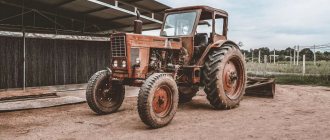
During long-term operation of special equipment, breakdowns inevitably occur, usually in the most loaded functional units. Thus, relatively often there is a need to repair the chassis of tracked tractors, so it is worthwhile to comprehensively consider the malfunctions that lead to this and the general repair technology. Knowing the risk factors that cause the carriage, chains and other elements to fail, you will understand how to protect them and thereby extend the time of trouble-free use of the machine.
Due to its design, this type of special equipment performs well on weak-bearing soils and in difficult, rough terrain, so it is important to maintain it in ideal working condition.
Tractor chassis - what is it?
This is a key functional unit of the vehicle, ensuring its direct movement in space at a speed specified in the operating range. In fact, this is a platform (trolley) with units installed on board, and, in addition to the main role already mentioned, it is designed to solve 3 more important tasks:
- support of the frame with all mounted and operated mechanisms;
- converting torque (coming from sprockets or drive wheels) into translational motion;
- generating sufficient traction force to tow trailers and/or other vehicles.
Classification of agricultural tires
Tires for agricultural machinery can be classified into:
- tube and tubeless;
- radial and diagonal;
- leading, guiding and carrying.
The drive wheels must have an all-terrain tread pattern. They are installed on the rear axle of tractors, as well as the steering wheels of combine harvesters. Can be installed on the front axle of off-road tractors. Regulatory documents also allow the installation of such tires on the load-bearing wheels of agricultural machines and implements.
Guide wheels are installed on the front axle of tractors and the rear axle of combine harvesters.
Load-bearing wheels are designed for installation on trailers and agricultural implements (machines).
The design of the undercarriage of a caterpillar tractor
It consists of 3 parts:
- The skeleton - performs a load-bearing function. This is a system that connects other nodes.
- The propulsion unit - receives the load torque from all installed units (as well as from the transmission), which converts it into translational movement along a given trajectory.
- Suspension – connects axles to the body (frame), transfers the weight of special equipment to the ground, softens vibrations, shocks and shocks, thereby improving the smoothness of the ride.
Each of these parts deserves a more detailed look.
There are three options for the frame:
- Frame - spinal or spar, that is, from a pair of longitudinal steel beams with cross members. It forms a solid or hinged structure, but it must be rigid, durable, and provide easy access to the mechanisms used.
- Semi-frame - obtained by connecting the transmission housing and the supporting metal structure in the shape of the letter “H”. It is to the latter that the front axle of the propeller is attached. It is distinguished by its low weight (compared to the previous subspecies) while maintaining sufficient resistance to loads and vibrations.
- Frameless - created by rigidly joining the housing elements of the power transmission and crankcase, as well as, optionally, the clutch and rear axle. It somewhat limits access to the units mounted on board, so it is used relatively rarely.
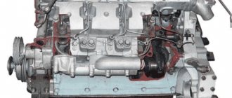
The propulsion unit is a structurally complex unit of the chassis of caterpillar tractors; its structure is as follows:
- the drive sprocket, responsible for movement, engages the chain;
- the latter consists of articulated links and creates a closed loop (circuit), going around the support rollers, the guide wheel and the support rollers;
- lugs form a rolling path for special equipment;
- the support rollers evenly distribute the acting force of gravity over the entire surface of the track;
- rollers perform a supporting function, preventing lateral swaying;
- The tensioning mechanism and guide wheel set and maintain the correct trajectory of movement while maintaining proper shock absorption.
This design of the propulsion device provides the running gear of tracked vehicles with high quality traction with the ground at a relatively low pressure on it, as well as good cross-country ability. Hence the frequency of operation on swampy or sandy soils, in difficultly rugged areas. But there is also a drawback - it is slower than wheeled models, which somewhat limits the versatility of use.
The suspension can be:
- Elastic - is a system of levers and rollers (elastic and arranged in pairs into a carriage), which are attached to the frame using hinges. Helps the track follow the surface topography, which improves the smoothness of movement.
- Semi-rigid is a trolley with beams of various diameters and elements located on them. Its frame is connected to the frame at the rear, and in front is in contact with a flat spring. Its design is simpler than the previous version (which means fewer parts can fail), but the quality of vibration absorption is worse.
Purpose and advantage of crawler tractors
The caterpillar tracks provide increased traction with the ground, which increases off-road capability. Using this technique, you can go into the fields immediately after the snow melts or after spring floods, in wetlands. There are other advantages:
- The increased clutch area ensures machine maneuverability and reduces the turning radius, which has a positive effect on fuel consumption.
- A belt-driven tractor provides high efficiency while simultaneously reducing the load on the soil, which prevents soil compaction.
- One of the purposes of machines on tracks is to work with bulldozer equipment due to their high traction performance.
- Due to their good balancing and high load capacity, tractors are used when installing technological equipment.
Basic malfunctions of the crawler tractor chassis
Before examining them in detail, let us explain the nature of their occurrence. The key reason for the appearance and development of defects is the unevenness of perceived loads.
It should be taken into account that the functional components of special equipment are operated in an abrasive environment, often in the presence of dry friction. And the same tracks are also constantly in contact with the soil, of very different hardness and condition. Add here seasonal climate changes, as well as sudden changes in humidity, and you get all the prerequisites for intense wear.
Two simple examples:
- In a number of Soviet models (for example, the T-74), the rear support during use experiences a load 3 times more severe than the front one. Naturally, in such conditions it will be necessary to periodically carry out repairs as part of the maintenance of the undercarriage of a caterpillar tractor.
- If you attach a plow to the same machine, during operation its front axles and bushings will be loaded by 24 kN, while the rear ones will be loaded by 41 kN. It is clear that it will fail sooner.
Another risk factor is temperature, because its drop leads to a change in the viscosity of the oil. Thus, already at -15 0C, moving special equipment at the same speed as at +5 0C requires 2.5 times more energy consumption. In this case, the friction force increases proportionally, which means the wear of parts in contact with each other accelerates.
It is also worth remembering that in the process of constant contact with each other, the parts are mechanically deformed. Abrasion of the contacting surfaces occurs, which leads to a deterioration in the quality of adhesion.
As an example of the variety of defects that arise, here is a summary table of defects in the rear axle of a caterpillar tractor.
| Breaking | Reason for appearance and development | Elimination method |
| Oil is leaking | Damage to gaskets or seals. Loosening of components. | Replace the worn element. Tighten the bolts well (but not too tightly). |
| DBA does not work | The clutch discs are oily. The friction linings are worn out. | You wash dirty components or install new ones instead of outdated ones. |
| The case is overheating or noisy | The clearance between bevel gears or bearings exceeds the permissible limit. There is not enough oil. | Adjust the distance until it is suitable. Add lubricant. |
| When driving on flat terrain, special equipment moves to the side | The spring that brakes the sun gear has weakened. The control levers do not move freely. The brake band linings are worn. | Replace the used part/element. Adjust the stroke until free. |
| The rotation command is poorly executed | The mechanism for performing maneuvers is not configured properly. The parking brake linings are oily or worn out. | Debug the operation of the control device. Install new components. |
Repairs to the rear axle of a crawler tractor can be prevented by periodically inspecting and listening to it. Regular checks allow you to promptly identify and eliminate malfunctions and operating errors with minimal consequences, tighten loose fastening nuts, calibrate bearings, and remove accumulated oil leaks. In this case, it is important to fill the lubricant no higher than the mark (control level) so that it does not leak through the seals. Next, we will separately consider those cases that occur more often and are more critical.
Broken suspension carriage
During operation, under the influence of uneven loads, this element develops the following defects:
- cracks and chips on the internal or external surface;
- broken lugs and/or abrasion of their holes;
- premature wear of the outer rings of tapered roller bearings and balancer bushings;
Such problems are typical for many Soviet and Russian-made models, in particular for the T-150, DT-75 and DT-75M. Although foreign special equipment, which is actively used on soft soils and in difficult rough terrain in our climate, also encounters similar damage.
Therefore, repairing caterpillar tractor carriages is, in principle, universal and consists of performing the following actions:
- In case of cracks, clean the surface near the defective area, strengthen the eye with pins (5-6 mm in diameter), bend them and weld the joint with electrodes E-46, E-42 (or others, but with chalk coating).
- When the technological hole intended for the swing axis wears out, bore out the space for the internal balancer, take a steel bushing of suitable cross-section, press it in, weld it at the ends, drill a seating point for the wedge (with a cross-section of 28 mm). The entire procedure can be easily carried out using mobile boring machines from.
- When the bushings themselves wear out - for the crossbar axle or for the swing axis - simply replace the damaged elements (since they can no longer be restored).
- In case of premature wear of the outer rings of roller bearings, widen the technological holes and install repair bushings of larger diameter in them.
Track failure
They operate in the most severe conditions, as they work in an abrasive environment and with temperature changes, and are in direct contact with other parts and the soil surface. Therefore, over time they wear out:
- the eyes of the links and fingers - in the areas of their interface;
- lanterns - at the points of their connection with the teeth of the drive sprocket;
- lugs and treadmills.
The procedure to follow here depends on what exactly went wrong. There are elements that are either economically unprofitable or unsafe to restore, since their further operation can lead to an accident.
Other types of repairs to tractor tracks are performed depending on the nature of the defect. For example, eye holes are repaired by crimping, subjecting them to plastic deformation. To do this, the link is placed in a container with molten salts, heated to a high temperature, and then compressed using stamps. As a result, the material of the part is redistributed with the original dimensions returning. Next, hardening is carried out so that the element acquires sufficient reliability. At the same time, damaged lanterns are also restored (this is the advantage of the method).
Another method is pouring liquid metal:
- A hole is burned in the eyelet - on the side where the wear is most serious, using a carbon electrode or an electric arc.
- After that, a sleeve is inserted into the resulting seat and covered with refractory clay on both sides.
- At the same time, steel is melted, either with a high-frequency connection, or in crucibles, and then the metal is poured into the eye.
- The metal fills the resulting cavities, cools and hardens, and turns into a kind of liner (or rivet), which allows the element to be restored to its original shape.
Crawler cranes are repaired using similar methods, since their undercarriage system is almost the same as that of tractors, and therefore receives similar damage.
Breakage of chains
Most often during operation, especially when special equipment is overloaded, the following defects occur:
- sagging of the track due to problems with the tensioner cylinder;
- weakening of the quality of the joint in the area where the drive sprocket is attached to the shoe;
- critical wear of 20% of bushings or more;
- no reverse gear;
- abrasion of lugs due to their constant contact with the hard surface of the ground.
Most problems are visually noticeable, which makes it possible to correct them at the earliest stages of manifestation. However, for your own peace of mind and work safety, it is worth carrying out ultrasonic flaw detection, which is performed as part of the maintenance of the undercarriage of a wheeled tractor or scheduled repair of a chain of a tracked vehicle.
Detected defects are corrected depending on their nature. Thus, when the track sag, the integrity of the surfaces of the tensioner cylinder is restored (by grinding and soldering), and if this is impossible or impractical, the part is replaced.
Repair of the shoe fastening is carried out in the presence of cracks deeper than 4 cm, a broken area exceeding 200 square cm, or abrasion of the ridges of more than 3 cm. Its shape is returned to its original shape using a hydraulic press.
Track rollers and lugs are repaired by surfacing metals of suitable hardness, followed by leveling the relief to the desired level using electrical contact or turning.
Driving and driven wheels of the tractor
Wheels consist of a pneumatic tire, rim, disc and hub. All modern wheeled tractors are equipped with low-pressure pneumatic tires. The air pressure in the tires of the driving wheels is in the range of 0.08...0.17 MPa, in the tires of the driven driven wheels -0.14...0.26 MPa.
Tires are divided by size, design and purpose. The tire dimensions and its design features are included in its designation 13.6R38 or 18.4-30:
the first number corresponds (in inches) to the nominal width of the tire section;
the second - the rim mounting diameter;
R is the designation of radial tires, and the dash between the numbers is the designation of tires with diagonal cords;
the letter L instead of R indicates that the tire is low profile.
Earlier tire designs had the same designation, but in millimeters.
According to the shape of the profile, tires are divided depending on the ratio of the profile height H of the tire to its width B. Tires are distinguished (Fig. 7.1):
— regular profile (N/V = 0.9…1.1);
— wide-profile (H/B = 0.75...0.85);
-arched (H/V- 0.4…0.6);
— pneumatic rollers (N/V = 0.1…0.4).
Tires can be tubed or tubeless.
Rice. 7.1. Geometric shapes of the tire profile and their imprints: a - regular profile (toroid); b - wide-profile; c - arched; g - pneumatic roller; d — landing diameter of the wheel rim; b — wheel rim width; D - outer diameter of the tire
A tube tire consists of a tire, a tube and a rim tape.
The tire cover (Fig. 12, a) has a complex structure and configuration and consists of a frame 3, a breaker (cushion layer) 2, a tread /, sidewalls 4, beads 6 and bead rings 5.
The tire carcass limits the volume of the inflated chamber and transfers loads acting from the soil or road to the wheel rim. It consists of several layers (2-14) of rubberized cord, superimposed on each other. By design, tires are divided into diagonal and radial. In bias-ply tires, the threads of adjacent carcass cord layers are crossed with each other at an angle of 95... 115°, forming a mesh. As a result, due to friction between the carcass layers, bias-ply tires have greater rolling resistance than radial tires. Modern tractors use radial tires, as they have increased wear resistance and lower resistance to lateral slip and rolling.
Rice. 7.2. Pneumatic tire: a - tube; b - tubeless; 1 — protector; 2 — breaker; 3 - frame; 4 - sidewall; 5-sided rings; 6 — board; 7 - valve; 8 — wheel disk; 9 — wheel rim; 10 — sealing rubber layer; 11 - sealing rubber layer
The materials used to make the cord are cotton fabric, viscose, polyamide resins and steel wire. When using a metal cord in a tire, its number of layers is reduced. These tires have high load-carrying capacity and wear resistance and are less prone to punctures when hitting sharp objects. Sometimes metal cord is combined with non-metallic cord.
A breaker is a rubber or rubber-cord layer between the frame and the tread. It serves to strengthen the frame, reduce shock loads on it and more evenly distribute traction, braking and lateral forces.
The tread is a thick layer of rubber located along the crown of the tire. It serves to ensure good adhesion of the tire to the supporting surface, weaken shocks and impacts on the frame and protect the frame and tube from mechanical damage.
The sidewalls are formed by a rubber layer that covers the frame from the side and protects the latter from moisture and mechanical damage.
The bead is the hard part of the tire that is used to attach it to the wheel rim. It is formed from wings wrapped with the ends of layers of cord. Depending on the number of cord layers in the side, one, two or three wings are used. The wing is made from a side ring made of steel wire, a solid profile rubber cord, wrapping and reinforcing tapes
The chamber is a thin-walled rubber shell in the form of a torus, into which air is pumped. For air inlet and outlet, the chamber has a valve equipped with a check valve.
The rim tape has the form of a flat ring and is installed between the tube and the wheel rim to protect the tube from abrasion on the rim and from being pinched between the tire and the rim.
Tubeless tire (Fig. 7.2,6). In it, a space filled with air is formed by a sealed connection between the rim and the tire, while the valve is placed on the rim. Tubeless tires can be conventional, arched or pneumatic.
Tires are characterized by a number of geometric parameters and load capacity, which depends on the internal air pressure.
By purpose, tires of driving and driven steering wheels are distinguished.
The drive wheels serve to convert the torque supplied to them from the engine through the transmission into the tangential traction force necessary to move the tractor and create traction on the hook. The tangential traction force depends on the mass loading the drive wheels, the contact area of the wheels with the supporting surface, the adhesion properties of the tread, as well as the properties of the soil or ground. To ensure reliable traction of the drive wheels with the soil, most (up to 70...75% for 4K2 or ZK2 tractors) or all of the tractor’s gravity force (for 4K4) is transferred to them. The tire tread has rubber lugs directed at an angle to the plane of rotation of the wheel, improving traction of the wheel with the soil.
The drive wheel of the MTZ-80/82 tractors (Fig. 73, a) consists of a rim 1 with a tire, a stamped disk 2 and a cast hub 4, connected by bolts 2, which are pressed into the holes of the hub flange. The disc and rim are rigidly connected to each other.
The wheel hub 4 with bolts 9 is rigidly connected to the axle shaft 6 using an insert 10 and a key 5. The insert is equipped with a worm 7, which is engaged with the rack teeth located on the axle shaft 6. Rotation of the worm 7 when the bolts 9 are released allows the wheel to move along the axle shaft 6 and setting the required track width.
To improve the traction of the drive wheels with the soil, removable weights 8 can be installed on disk 2.
The front drive wheel disks of the MTZ-82 tractor are bolted to brackets welded to the rim. This design allows you to change the relative position of the disk and rim and, thanks to it, to additionally adjust the track of the front wheels in steps.
The drive wheel of the LTZ-55/55A tractors (Fig. 7.3.6) does not have a hub and consists of a rim 1 with a tire and a stamped steel disk 4. On the inside, racks 3 are welded to the rim, to which disk 4, reinforced with bolts 2, is attached the place where it is attached to the axle flange with ring 6. To increase the adhesion weight when operating the tractor in difficult conditions, additional weights are installed
A step change in the track of the driving wheels is ensured by rearranging the rim 1 relative to the disk 4 and changing the position of the wheel disks relative to the axle flanges.
The drive wheel of the K-701/701M tractors (Fig. 7.3, c) is a diskless design with a wide-profile rim 1, mounted on the hub of the final drive carrier using clamps 2 and limiters 3.
This design of the drive wheel makes it possible to reduce the overall width of the tractor while maintaining ground clearance, since the final drive is located inside the wheel rim.
Driven steered wheels serve to direct the movement of the tractor, as well as to transfer part of its weight to the supporting surface.
If the steered wheels are driving, then they create additional tangential traction force.
The main requirement for steered wheels is to maintain stability of straight-line motion and a given trajectory of curved motion when turning.
To make it easier to turn the tractor and reduce the turning radius, the front steered wheels are usually made smaller in diameter and rim width compared to the rear drive wheels.
To reduce the lateral slip of wheels on the soil or ground when turning the tractor, the tire tread pattern is made in the form of annular ribs.
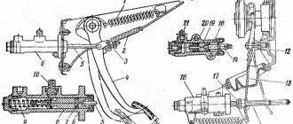
The idler wheel of the LTZ-55 tractor (Fig. 7.4, a) has a cast hub 2, on which a rim / is mounted, connected to the hub by linings 11 using bolts 12. One of the linings is located between the protrusions welded to the rim, keeping it from rotating relative to the wheel hub . Hub 2 is mounted on two tapered roller bearings 7 and 10 on axis 5, ending with a rectangular flange for connecting the axis to the kingpin. The hub is sealed from the outside with a cap 8, and on the inside - for the LTZ-55 tractor with frame 4 and felt 3 seals, for tractors T-25A/T-30A80 - with a mechanical seal (Fig. 7.4,6).
Rice. 7.4. Driven steered wheels: a - tractor LTZ-55; b - mechanical seal of the driven wheel hub of the T-25 A and T-30A80 tractors
The mechanical seal of the wheel hub consists of a rubber diaphragm 2, pressed to the housing 1 by a dirt-proof casing 7, and two steel rings: movable 6 and fixed 4 (Fig. 7.4,6). The rings are pressed against each other by lapped cemented surfaces using springs 5. The movable ring is secured against rotation relative to body I by pins 3. Housing 1 with seals is connected to the wheel hub with bolts 8.
The bearings of the steering wheels of tractors are adjusted using castle nut 9 (Fig. 7.4a). To improve controllability and stability when working with rear-mounted machines, removable weights are installed on the front part of the frame of the MTZ-80, LTZ-55, T-25A and T-30A80 tractors.
Repair technology for crawler tractors
From the outside it looks like this:
- You notice a malfunction and contact a company that specializes in professional repair of special equipment.
- Specialists carry out comprehensive diagnostics and, based on its results, draw up a defect report, in which they enter all the detected problems and indicate what operations need to be performed to solve them.
- Having secured the customer’s consent, the craftsmen carry out the agreed work - bore the lugs, weld on the road wheels, remove the lanterns and sag of the track, replace failed elements - do everything that is possible in the workshop.
Attention, there are parts that can only be restored at the factory. For example, links - they are sent either to the direct manufacturer or to a large industrial enterprise that produces their analogues.
There are also parts that can be restored at the site of special equipment, without transportation to a repair shop, if you use mobile boring and surfacing machines for this.
We tried to consider in as much detail as possible the purpose of the chassis system, the main parts of the caterpillar tractor, and the malfunctions that most often arise in the process of solving road transport problems. Now you know what to do in case of breakdowns, but is it worth it? Finally, we would like to give some banal but effective advice: try not to violate the operating conditions of special equipment and regularly send it for diagnostics - this will prevent the development of many problems.