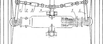
Steering is one of the most important mechanisms in any driven vehicle. It is he who is “responsible” for turning the guide wheels and, therefore, for all maneuvers of the tractor. It is very important to ensure that it is in good working order and accurately responds to the operator’s manipulations. The steering of the T-40 tractor consists of several elements: a steering column and a wheel located in the cabin, as well as a shaft and universal joints. To facilitate control, the T-40 is equipped with a power steering system - a hydraulic booster with a bipod.
Gear tractor T 40: disassembly, assembly, do-it-yourself repair
Steering is one of the most important mechanisms in any driven vehicle. It is he who is “responsible” for turning the guide wheels and, therefore, for all maneuvers of the tractor. It is very important to ensure that it is in good working order and accurately responds to the operator’s manipulations. The steering of the T-40 tractor consists of several elements: a steering column and a wheel located in the cabin, as well as a shaft and universal joints. To facilitate control, the T-40 is equipped with a power steering system - a hydraulic booster with a bipod.
Steering column design
The steering column of the T 40 tractor consists of the following elements:
- bipod;
- bracket;
- hydraulic booster (located under the hood in the front of the tractor);
- wedge;
- cardan;
- cardan shaft;
- steering column;
- shaft;
- steering wheel;
- screw;
- spring washer.
Spring washers exert load on the idler wheels. When the steering wheel rotates, pressure increases in the piston cavity. To prevent excessive compression of the springs, stops are provided. When turning the nut, you act on the spring washer, which increases the force on the steering wheel.
The hydraulic booster on the T-40 consists of a housing, a piston, a screw, a distributor, a bipod shaft, and front and rear covers. The T 40 power steering circuit is presented in any operating device.
Operating principle:
- The driver rotates the steering wheel, thereby generating torque.
- From the steering wheel, rotation is transmitted to the steering shaft and then to the cardan shafts and their shafts.
- The T 40 power steering perceives the rotation and strengthens it, turning the shaft with the bipod in the proper direction.
- The T-40 is equipped with a piston-type hydraulic booster. The hydraulic booster is lubricated through the throttle hole of the valve spool. When the tractor is operating, the oil flow is directed to the hydraulic booster and to the separate hydraulic system. A special flow valve is installed for this purpose. If the pressure in the power steering increases, the spool moves down, which increases oil flow.
- When a load is created in the mounted system, the spool moves upward, thereby reducing the oil flow to the hydraulic booster.
Design and principle of operation of the power steering of the T-40 tractor
Power steering is one of the elements of the T-40 steering structure. It is located under the hood, closer to the front. The main components that you will have to deal with during repair or maintenance are: covers (front and rear), stops, nuts, bipod, spool.
The power steering of the T-40 tractor operates on the principle of a piston. The oil is dosed by a spool located inside the piston.
Power steering
Algorithm of operation of the T-40 power steering:
- hydraulic fluid is supplied from a gear pump;
- The spool valve distributes the flow to the rear linkage and tractor steering;
- pressure is supplied to the T-40 steering column.
When the steering wheel rotates, two nuts in relation to the piston move as follows: one moves towards the end, and the other moves away. Therefore, the oil flow always moves in one direction, tending to the open drain hole.
what to choose, power steering or mountain?
Steering is a system of units, mechanisms and devices that provide a change in the direction of movement of the tractor.
MTZ-80 tractor steering wheel drive diagram
In wheeled tractor models, the direction of movement of the machine is changed by turning the front steered wheels to different angles. When turning, the front and rear wheelsets describe an arc around a common center located on the extension of the rear wheel axle.
System composition
The operation of the steering system is based on the interaction of the steering mechanism, which performs the function of transmitting control input from the operator's steering wheel with the steering mechanism, which converts the force transmitted to it into turning the wheels.
The control system for the direction of movement of wheeled tractor equipment includes:
- A steering linkage installed on the front axle, formed by two transverse rods connected to each other by the bipod, the ends of which are in contact with the swing arms;
- Connected by cardan joints are sequentially located steering, intermediate, middle and front shafts, transmitting the rotation of the steering wheel to the hydraulic booster;
- A steering wheel with variable height and tilt mounted on the front shaft located in the steering column tube;
- Steering column with mechanisms for tilting and changing the height of the steering wheel;
- Mounted in one housing, located in front of the radiator, the steering mechanism and hydraulic booster provide an intermediate hydraulic and mechanical connection between the operator’s steering wheel and the tractor wheels;
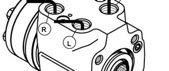
- The hydraulic circuit that ensures the operation of the hydraulic booster, which includes a gear-type pump, a working fluid distributor, a power cylinder and a sensor that issues a command to lock the rear axle differential;
- A steering mechanism consisting of a worm placed in an eccentric bushing supported by two radial bearings; a double-crown sector, which is in constant contact with the worm and rack connected to the rod of the power cylinder; and a spool mounted in the tail part of the worm;
- The rotary shaft and bipod transmit the movement of the sector to the steering linkage units.
Device, diagrams, repair
T-40 tractor hydraulic booster (power steering): design and repair
Power steering on the T-40 tractor to reduce the force on the steering wheel used by the tractor driver when making turns. The power steering is located in the front engine compartment of the tractor and is mounted on the front frame bar.
Power steering device
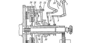
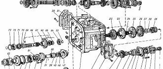
The hydraulic booster consists of a housing, a distributor, a piston, a screw, a bipod shaft, and rear and front covers. The housing contains a piston equipped with a through hole for installing a screw. The screw has a left-handed four-start trapezoidal thread onto which the rear and front nuts are screwed. Both nuts are secured with pins to prevent them from turning. The rear pin, installed in the holes of the rear nut and piston, is pressed by a spring. According to operating conditions, the power steering screw should not have axial movements. As a result, the bearing is fixed on the screw with a slotted nut, locked with a pin.
The switchgear kit includes: a hydraulically controlled spool, stops, piston, springs, rear and front nuts.
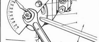
The piston has three teeth that engage with the teeth of the bipod shaft. During assembly, the middle tooth of the piston is inserted into the middle cavity of the sector. The gap in the engagement of the sector with the piston is adjusted using a special adjusting screw.
The device of the hydraulic booster of the T-40 tractor: 1 - bipod shaft; 2 — front cover; 3, 5 - nuts; 4 - ball bearing; 6 — front nut; 7 - spring washer; 5 - seal; 9 - piston; 10 - body; 11 — top cover of the housing; 12, 23 — adjusting screws; 13, 22 — cap nuts; 14 - pin; 15 — power steering screw; 16 — back cover; 17 — rear nut; 18 — emphasis; 19 — spring; 20 — spool spring; 21 - spool; 24 - safety valve; 25, 26 - traffic jams.
Operating principle
When the tractor is operating, the oil flow supplied from the hydraulic system using a pump is divided into two branches: to the hydraulic booster and to the separate hydraulic system. This division of the oil flow is carried out by a division valve. The throttle opening of the flow valve spool bypasses 10-12 liters of oil per minute, which is necessary for the functioning of the power steering of the T-40 tractor.
As the pressure in the hydraulic booster increases, the spool moves down and throttles the output from the valve to the linkage system. In the event of a load created in the mounted system, the spool moves upward and throttles the output from the flow valve to the hydraulic booster. If there is a simultaneous load on both branches, the spool takes a neutral position.
When the tractor steering wheel rotates, both nuts move relative to the piston so that one of them approaches the end part of the piston and throttles the drain hole; the other one moves away from the end of the piston, opening the drain hole. The oil flow, previously split in half and passing through both cavities, will now flow into the cavity with the open drain hole.
Related Posts
Which tire is better to buy for the rear wheel of a T40 tractor?
- Author: Azat Bulatov
- October 29 00:00
Everyone is healthy. Please advise what tire to buy for the rear wheel of the T40 tractor. Which brand of oak, non-oak should I buy?
I'm making a dispenser on a mini. I connected everything, pump nsh10 directly from the engine. Through the coupling. Why does the steering wheel turn with great effort?
- Author: Evgeny Shatskikh
- 06 October 23:00
- 64 comments
Hello tractor drivers. This is the question I came across. I make a dispenser on a mini. I connected everything, pump nsh10 directly from the engine. Through the coupling. The steering wheel turns, but with great effort. I thought the dispenser was bad. I put another one. from a working MTZ. On the MTZ the steering wheel works with 1 finger, on the Mini - cherushki. I made a mistake with the RVD AT FIRST, but after looking at the MTZ 1221 I realized that the RVD is the same in diameter, but the steering wheel is tight. As engine speed increases, the steering wheel does not become lighter. The pump is new.. What's the problem, tell me? Maybe try increasing the speed through a belt or some kind of gearbox?
What kind of oil should I put in the T-40 for the winter?
- Author: Yuri Tikhonov
- September 28 10:10
Good morning. Guys, what kind of oil do you use for the winter? T-40
Why does the steering stick? Recently I changed the pipe, the left king pin, a new pump, and the right king pin.
- Author: Ilnur Sadriev
- September 27 10:10
- 4 comments
Hi all. Problem. Why does the steering stick? I recently changed the pipe, the left pin, the pump is new, and I changed the right pin in the spring.
Why does the T40 tractor constantly tear off the clutch bolts? What bolt can I replace it with?
- Author: Azat Bulatov
- 05 September 14:10
- 24 comments
Do-it-yourself repair of power steering tractor T-40
The price for a T-40 power steering ranges from 10-13 thousand rubles; a comprehensive repair will cost about the same amount. Therefore, making repairs yourself and performing maintenance yourself is the best option for the tractor owner. Thanks to the video, you can learn in more detail about the repair of the T-40 steering column.
Disassembly and assembly
Disassembling the T-40 power steering is performed according to the following instructions:
- when disassembling the piston assembly, press the pin located in the rear nut all the way;
- the nut must be unscrewed and removed together with the spring washer;
- The screw is pushed towards the front cover, then the spool with springs and stops is removed.
problems with the T-40AM tractor
Questions can only be asked after registration. Please login or register.
Explain the reason for the boiling of the working fluid in the hydraulic system of the T-40 tractor and the operating principle of the flow valve. Thanks in advance
Check if one of the distributor levers is engaged, also check if the bypass valve on the distributor is stuck
wash the oil filter; it is on the hydraulic tank; if the mesh is clogged, oil then begins to pass through the emergency valve (a tube with a spring and a ball)
The jester knows the principle of operation of this flow distribution valve. Here on the forum I read about tandem pumps. I will look for and install it, otherwise there will be trouble with this steering one.
The jester knows the principle of operation of this flow distribution valve. Here on the forum I read about tandem pumps. I will look for and install it, otherwise there will be trouble with this steering one.
If you are interested, the operating principle of the flow division valve. Files: kl.jpg
_______________________________________ “Do what you can, with what you have, where you are.” Theodore Roosevelt ©
and in your own words, if possible, otherwise something is confusing
and in your own words, if possible, otherwise something is confusing
Damn, this is a question worth a hundred points, I’ll try my best.
When the steering wheel is not turned and the hydraulics are not used, the oil passes through the power steering and distributor with virtually no resistance. In this case, the pressure in the chambers under and above the spool is the same, and it hangs in the middle, supported from below by oil pressure and from above by spring pressure. When the steering wheel was turned, the oil passage in the power steering was blocked and the pressure in the chamber above the spool rose, it is added to the spring force and the spool is pressed down. When the spool went down, it blocked the outlet to the hydraulic distributor with its body. It will remain in this position as long as the steering wheel rotates. As soon as the steering wheel was stopped, the pressure above and below the spool was equalized again and it returned to the middle position. When the hydraulic distributor lever was pressed, the oil path in it was blocked and the pressure began to increase under the spool, the pressure that was there initially is added to it, and their sum, overcoming the spring pressure, lifts the spool up. At the same time, he blocks the exit to the steering wheel with his body. When we simultaneously turned the steering wheel and turned on the lever on the distributor, the pressure rose equally both above the spool and below it, it will become equally high in both places. In this case, the spool also hangs in the middle, supported from below by the sum of the increased and initial pressure, and from above by the sum of the increased pressure and spring pressure.