The steering control of the MTZ-80, 82 tractor is used to change and maintain the selected direction of movement.
The main way to change the direction of movement is to turn the front guide wheels in a horizontal plane relative to the rear ones.
The steering must ensure correct turning kinematics and traffic safety, small forces on the steering wheel, and also prevent the transmission of shock from surface unevenness to the steering wheel.
The steering gear increases the driver's effort on the steering wheel and improves steering precision.
Thanks to this, it remains possible to control the tractor when the hydraulic booster is not working, for example, when the engine suddenly stops, which increases traffic safety.
The hydraulic booster (power steering) facilitates control and increases the safety of its movement.
The MTZ-80, 82 hydraulic booster, using engine energy to turn and hold the wheels, improves the maneuverability of the tractor and ensures control in difficult conditions, for example, in the event of sudden tire damage.
When driving on uneven and difficult terrain, the hydraulic booster reduces shock loads in the steering, reducing the likelihood of damage and increases steering safety.
Steering MTZ-82, 80 consists of a steering mechanism and a drive. Through the steering mechanism, the force applied to the steering wheel is transmitted to the steering gear.
The steering drive transmits forces from the steering mechanism to the steered wheels.
The steering is mechanical with hydraulic booster. The steering mechanism and hydraulic booster with an automatic differential lock sensor form a common unit and are located in the front part of the tractor.
Therefore, the steering gear drive is designed to transmit force from the steering wheel to the steering mechanism and hydraulic booster.
Maintenance of the steering mechanism drive of the MTZ-80, 82 tractor
Fig.1. Maintenance of the steering gear drive MTZ-82, 80
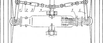
The steering drive transmits the forces of the driver and the hydraulic booster to the steered wheels, ensuring their rotation at mutually different angles.
Maintenance of the steering gear drive consists of periodically checking the tightness of the threaded connections.
To ensure minimum vibration levels in the steering wheel, adjust the steering column as follows:
– remove cover 5 (Fig. 1); loosen clamp 4 and remove steering wheel 6;
– loosen locknut 3;
– screw nut 2 until it comes into contact with bushing 1 so that the gaps in the connections are selected;
– unscrew nut 2 by 1.5 turns and lock with lock nut 3.
– install the steering wheel 6, adjusting its position in height.
Washing the power steering drain oil filter of the MTZ-80, 82 tractor
Fig.2. Washing the power steering drain oil filter MTZ-80, 82
To wash the oil filter, do the following (Fig. 2):
– disconnect oil lines 7, 13 and 15, unscrew bolts 5 securing cover 6 to the body, use two dismantling bolts to remove the cover;
– unscrew pressure reducing valve 11 and remove drain filter 9;
– rinse the filter in a washing solution;
– tighten the nut 8 of the rotary shaft;
– install the filter and perform the operations in the reverse order of disassembly;
– at the same time adjust the axial play of the steering shaft, for this purpose: loosen locknut 1 and screw the adjusting bolt 2 until it stops at the end of the shaft, then unscrew it 1/8-1/10 of a turn and lock it with locknut 1.
Filling, checking the level and changing the oil
Check the level and add oil according to the recommendations of the lubrication chart. It is strictly prohibited to operate the tractor if the oil level is below the lower mark on the oil gauge 4 (Fig. 2).
When changing the oil, wash the filler filter.
After changing the oil, start the diesel engine and turn the steering wheel from lock to lock several times, check the oil level again and, if necessary, add to the upper mark of the oil gauge.
Steering malfunctions MTZ-80.82
The installation of power steering (power steering) in the hydraulic system of the MTZ-82, 80 tractor is caused by the need to reduce turning effort, reduce tractor driver fatigue, improve traffic safety and the quality of work performed.
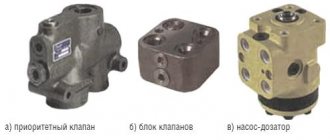
The steering hydraulic system includes an oil tank, a high-pressure pump, a distributor with spool devices, a power cylinder, fittings and pipelines. Tractors are equipped with power steering (power steering) of monoblock designs.
With a monoblock design of the hydraulic steering system, the pump supplies working fluid to the spool distributor of the power steering, in which a double-acting power steering cylinder is mounted.
The force from the piston of the power cylinder is transmitted through the rack and sector to the vertical shaft and bipod, which is connected through a transverse rod to the rotary wheels of the front axle.
The main control element of the steering hydraulic system is the steering gear distributor.
Malfunctions of the hydraulic steering system MTZ-82, 80
The quality of work performed by a tractor unit and traffic safety largely depend on the technical condition of the units of the hydraulic steering system.
When the oil in the hydraulic system is warm, the rotation of the steering wheel should be smooth, without jerking and without applying significant force.
Large free play of the steering wheel when the diesel engine is running indicates wear on the steering shaft connections and an increased gap in the meshing of the power steering gear.
First, the technical condition of the connecting parts of the steering mechanism, steering rods is checked and gaps are eliminated, parts are replaced or adjusted.
A device is used to determine the gaps in the gear or worm gears of the steering mechanism, as well as the force on the steering wheel rim. It is installed on the steering wheel, and the pointer is on the steering column.
By rotating the steering wheel in both directions to eliminate gaps in the steering rod joints and the engagement of the steering mechanism, the free play of the steering wheel is determined.
The nominal free play should be within 25.30, permissible - 35. Using the device, you can simultaneously determine the force on the steering wheel rim.
To do this, disconnect the steering rods from the bipod, start the diesel engine and, at maximum crankshaft rotation speed, pull the handle of the device’s dynamometer.
The position of the locking ring on the opposite handle determines the force of free rotation of the steering mechanism.
The force on the wheel rim should be within 30.50 N. If the free play exceeds the permissible values, the mechanisms are adjusted.
Rice. 1. Adjusting the free play of the power steering shaft MTZ-80, 82
1 — limb protractor; 2— bolt; 3— eccentric bushing; 4— mounting blade
Gaps in the gearing (worm - sector) (Fig. 1) are eliminated by turning the adjusting sleeve 3, having previously unscrewed the locking bolt 2.
If the free play of the power steering shaft has decreased slightly, remove the housing cover and use a feeler gauge to check the gap between the stop and the rack.
It is adjusted by gaskets on the differential lock sensor flange. Then the worm-sector engagement is adjusted again, achieving minimal free play and free rotation of the worm without jamming.
Disassembly, assembly and adjustment operations performed during the repair of power steering MTZ-82, 80 are complex and require the use of testing equipment after final assembly.
For hydraulic boosters, to replace the worm and sector, remove the top cover of the hydraulic booster housing and remove the vertical shaft assembled with the sector.
Then, by removing the distributor housing cover, remove the worm assembly with the distributor housing from the eccentric bushing.
To replace the worm, unscrew and unscrew the castle nut and remove the worm shaft from the distributor housing.
If the worm ball bearings have significant radial play, they should be replaced. When replacing a sector, it is pressed off the shaft using a two-jaw puller. The new sector is installed by aligning the mark on the end of the spline of the vertical shaft with the mark on the spline cavity of the sector.
When installing the vertical shaft into the power steering housing, align the marks on the middle tooth of the sector and the cavity of the rack.
For power steering, the piston and power cylinder rod seals are easy to replace.
To do this, unscrew the nuts of the mounting studs and remove the front cover, and then the power cylinder liner. If rod seals need to be replaced, remove the piston and rear cover of the power cylinder.
When assembling the power cylinder, the piston is first installed in the sleeve. Then the sleeve together with the piston is put on the rod and the recess of the rear cover. The piston nut is tightened to a torque of 120 Nm.
The final operations of assembling the power steering are adjusting the axial movement of the vertical shaft and the gap between the worm and the sector.
The gap between the worm and the sector is adjusted using eccentric bushing 3 (see Fig. 1). To measure the free play of the worm shaft, you can use a simple device - protractor 1 with a dial printed on it.
Design and principle of operation
The cast iron housing of the MTZ 80 (82) power steering is located on the front frame beam between the front front wall of the hood and the diesel engine cooling radiator of the machine. The unit is a mechanism with a worm gearbox, equipped with an autonomous hydraulic system with a spool for controlling the flow of working fluid, a left-hand rotation gear hydraulic pump NSh-10-L-U GOST 8753-71, a double-acting power cylinder and a safety valve. The system's hydraulic pump is driven by the engine timing gear.
A worm is installed in the amplifier body, connected by turns to the sector and its end part to the valve spool of the assembly. At the ends of the spool there are thrust bearings, into which the plungers rest under the pressure of the springs. At the same time, the outer sides of the plungers rest against the housing parts of the distributor. Plungers and springs hold the spool in the neutral position through bearings. When the steering wheel rotates, the worm begins to move the sector in turns, turning the bipod shaft. The resulting resistance of the wheels is transmitted through the mechanism to the worm, forming a force that moves it axially forward or backward depending on the direction of rotation. By its displacement, the worm interacts with the valve spool of the assembly, moving it relative to the axis. Thus, the spool controls the flow of oil under pressure. When moving straight, the distributor spool, spring-loaded, is in the neutral position, the pressure supplied by the pump is released into the amplifier housing, which is the hydraulic tank of the system.
By rotating the steering wheel, the worm moves the spool, which opens the lines of the cavities of the power cylinder with its belts. Moreover, depending on the direction of rotation, one cavity is connected to a line supplying oil under pressure, the other to a drain. The spool drops pressure into the cylinder cavity only during direct rotation of the steering wheel. When the steering wheel stops, the worm stops acting on the distributor spool, which, under the force of the springs, takes a neutral position, dumping oil into the drain cavity.
The piston of the cylinder 25 interacts through a rod with a rack 14 connected to sector 12 . When the spool supplies pressure to one of the cavities, the rod transmits force to the rack moving the sector, facilitating the rotation of the shaft 28 connected to the bipod 13 . The working pressure in the hydraulic system is 2-4 MPa. By turning the steering wheel to the maximum angle of rotation, the pressure reaches its maximum value of 8 mPa and is limited by safety valve 7 .
The driver’s feeling of “Road Feeling” of resistance to turning during steering is provided by the pressure from the discharge channel in the cavities with springs acting on the plunger. When controlled without force, the worm does not interact with the spool and the hydraulic system does not participate in the amplification.
Additionally, the unit is equipped with a differential automatic locking sensor located in the rack stop. The device includes a spool 21 , a rotary valve 18 with a flywheel, a pusher and a probe 20 . An unregulated pressure reducing valve maintains a pressure of 0.7-0.9 MPa in the locking hydraulic system. The device provides differential locking when driving straight and automatically turns it off when the wheels are turned more than 8 ̊.
Characteristics of components of the MTZ 1221 mountain control system
The components and parts described below are also used in the steering control of other models of MTZ Belarus tractors.
Pump
Gear pump of the NSh-14 system of left rotation with a capacity of 14 cm³/revolution. This pump is also used on Belarus tractors with reinforced beam axles (on the MTZ 82.80, a left-hand rotation pump NSh-10 is installed as part of the power steering or mountain control unit).
pump NSh-14 with drive
Steering dispenser
Gerotor type unit with a volumetric supply of working fluid of 160 cm³/per revolution for models Danfoss, Rexroth, Hydraulic, Lifam. The response pressure of the safety valve of the unit is 20 mPa, the response pressure of the shock-proof valves is 14 mPa (140 kgf/cm²). (MTZ 82 HSU is equipped with a dispenser with a capacity of 100 cm³/per revolution with the same indicators of safety and shock-proof valves.)
The anti-shock valves, by their operation, smooth out peak hydraulic loads resulting from the reverse reaction of the front wheels when driving along bumps.
dosing pump D160
Hydraulic cylinders
Two hydraulic cylinders of the Ts50-3405215 brand with a working stroke of 200 mm, a cylinder diameter of 50 mm, a rod diameter of 25 mm. In the connecting joints of the rod and cylinder body, spherical plain bearings of the ShS 25 brand are installed (d - internal diameter for the pin 25 mm, D - seating diameter of the outer race 42 mm, B - height of the internal spherical insert 20 mm, C - height of the outer race 16 mm ) Hinge pin with catalog number 102-3405103 (length 130-133 mm, threads M20x1.5, M24x2, maximum cone diameter 32 mm, taper 1:8).
Composition of the MTZ 1221 steering hydraulic cylinder
Steering column
The position of the steering wheel is adjustable: in tilt angle in steps from 40 to 25° in steps of 5°, in height in infinitely variable within 100 mm. The permissible free play of the steering wheel should be no more than 25°.
Steering column MTZ 1221
Tank system
Separate HPS hydraulic tank with built-in oil filter, filling volume 9 liters. The normal oil level in the HPS tank is considered to be within the immersion limit of the filter from the base to the middle of its body. The filter element, brand 601T-1-06, is cylindrical paper, height 100 mm, outer diameter 60 mm, inner diameter 24 mm.
Hydraulic tank mount MTZ 1221
Adjustments
The node is configured in good condition. Its correctness is an important factor in the efficient operation of the amplifier and preservation of its service life. The adjustment is divided into adjusting the gearing gaps of mechanical pairs and the spool stroke.
Worm-sector engagement
The adjustment is made when the steering rods and steering joints are in good condition; the free play of the steering wheel should not exceed 30 ̊ with the engine running.
- The front axle of the tractor is jacked up or the bipod is disconnected from the steering rods.
- Loosen the bolt of the adjusting eccentric sleeve.
- Turn the bushing clockwise until the worm stops in maximum engagement with the sector.
- With the engine running, turn the steering wheel to determine the engagement position without feeling stuck, increasing the gap by turning the bushing counterclockwise.
- Tighten the bushing mounting bolt, remove the bridge from the jack or connect the bipod to the steering rods.
Tightening the worm spherical nut
Tightening the nut eliminates the gap between the spool and the bearing races, formed as a result of wear or weakening. The appearance of a gap is reflected in an increase in the free play of the steering wheel and the appearance of the effect of dangling steering wheels. When play appears, the spool can arbitrarily connect the cylinder cavities to the oil pressure lines.
- Unscrew the bolts securing the distributor to the amplifier body.
- Remove the cover and attach the distributor to two diagonally placed bolts 5 . The thickness of the cover flange is compensated by backing washers 4 or large diameter nuts under the bolt heads.
- Then unscrew the adjusting nut 1 and tighten it until the spool stops in the bearing races. Tightening is carried out with a force of 20 Nm.
- By unscrewing the spherical nut until the hole on the worm shaft first matches, the nut is secured with a cotter pin.
- Dismantle the installation bolts with washers and install the cover with the gasket, tightening with four bolts as usual.
Correct tightening ensures that the spool fits snugly against the bearing races and ensures that the spool returns to the neutral position under the action of the springs when the steering wheel stops rotating. Excessive tightening increases the force on the steering wheel and leads to rapid wear of the distributor thrust bearings.
Adjusting the sector-rack engagement
The gap in the sector-rack engagement of the cylinder piston rod is regulated by the number of spacers between the amplifier body and the rack stop. A sufficient gap of 0.25-0.3 mm ensures the pair operates without jamming.
Spool stroke uniformity
The spool stroke is controlled by shims between the amplifier body and the distributor, the distributor and the spherical nut cover. If the rotation to the left is insufficient, an additional gasket of 0.5-1 mm is installed between the column body and the distributor; if the rotation to the right is insufficient, a gasket is installed under the spherical nut cover. Thus, the amplitude of the spool stroke from left to right is equalized.
System pressure
The pressure of safety valve 7 is adjusted by changing the spring compression. By tightening the valve screw, the compression of the spring increases and, accordingly, the maximum operating pressure of the amplifier hydraulic system.
Scheme of MOUNTING MTZ 1221
Structurally, the metering pump is installed on the steering column bracket and is connected by its spool through a cardan joint to the steering axis. Two hydraulic cylinders for turning the steered wheels are installed in front of the tractor on the front drive axle. The hydraulic pump is driven directly from the diesel engine. The metering pump is connected by its hydraulic outlets to the cavities of the hydraulic cylinders, the pump and a separate hydraulic tank via oil lines.
Scheme of MOUNTING MTZ 1221
List of parts for the MTZ 1221 mount control system
When the wheels are positioned straight, the cavities of the hydraulic cylinders are locked by the spool bands of the metering pump, and the oil supplied by the gear pump, passing through the metering channels, is discharged into the hydraulic tank of the HPS system. By turning the steering wheel, the metering valve moves relative to the distributor sleeve and opens the supply of oil pressure to the cavities of the hydraulic cylinders corresponding to the rotation in an amount proportional to the angle of rotation of the steering wheel.
It should also be noted that modifications of MTZ 1221 marked “B” are equipped with a reversible control station, where the system has an additional steering column located behind the driver, with an additional metering pump, along with redundant pedals for the brakes, clutch and fuel (gas) supply. . The transition to the reverse control mode is carried out by switching the oil pressure flow to the reverse column using a valve built into the system. To avoid the risk of rupture by peak pressure of the hydraulic lines when switching, the transition to reverse mode is carried out with the engine turned off.
Latest abstracts
The seal at the ends of the gears is ensured by two plates 12 installed in the recesses of the bearing and pressure races in the high-pressure zone near the discharge hole B. Conventionally, the path of the oil in the distributor is shown in Figure b. If there are no spare hoses, tighten the union nut of the locking device as far as it will go; if this does not help, free it from the balls, springs and crosses and screw the union nut back in completely.
It is installed vertically, but the cover with the spool control handles is not up, but down. Fork fingers 15 fit into the annular groove of gear 3.
The system is unloaded by a bypass valve. The top cover of the tank contains a filler neck, oil meter 10, breather, and filler filter.
The hydraulic system devices fixedly mounted on the tractor are connected by seamless steel pipelines designed for pressures up to 32 MPa, and fluid is supplied to the hydraulic cylinders through flexible hoses.
The driven gear is integral with the axle and the drive gear axis is hollow to drain oil from the seals.
As the mating surfaces of the gear teeth and race wear, this force moves the race toward the gears, thereby providing the required minimum clearance between the outer surface of the teeth and the sealing surface of the race.
The pump drive shaft seal seal is installed and a channel is made in the cover to drain leaked oil to the seal. I’m changing NSh 10 to NSh 16 to MTZ 80 and let’s chat).
See also: blocking does not work on MTZ-80
Malfunctions and repairs
The first criterion affecting the efficiency of the unit is the tightness of all seals of the hydraulic system, which maintain the working pressure of the fluid, providing force on the working parts. Elimination of oil leaks and pressure loss is achieved by replacing all rubber seals, O-rings and gaskets included in the complete power steering repair kit.
The serviceability of the joints of the mechanical drive, the adjustment of the engagements of the worm gearbox and the piston rack with the sector ensure the operation of the mechanism without jamming.
The reason for a tight steering wheel, if the system is well sealed and the oil level is sufficient, may be poor compression of the power piston of the amplifier cylinder or insufficient stroke of the distributor spool, which does not allow opening the discharge line to the cylinder cavities.
What is power steering MTZ
The Minsk Tractor Plant has provided all its Belarus equipment with a hydraulic booster, primarily in order to make it easier for tractor drivers to control a tractor equipped with attachments. Indeed, under its influence, a double load is placed on the front wheels, and the driver has to exert the maximum amount of effort to control such a heavy machine. The MTZ power steering has a built-in hydraulic system, the design of which includes the following main elements:
- Distributor.
- Metering and power cylinder pump.
- Rear axle differential lock sensor.
The design of the MTZ power steering includes the following structural elements:
- The housing, which contains the container where the required oil will be stored, and the bases to which the parts will be attached.
- A pump designed to move oil in a hydraulic circuit.
- A sector attached to a rotary shaft that constantly comes into contact with the steering element.
- Rotary shaft, which has 3 points of support. With its help, the turning movement is transmitted to the bipod, which, in turn, is connected to the front wheels of the vehicle.
- The rack comes into contact with the moving sector and transmits piston movement to it.
- A spool attached between 3 pairs of sliders, which are held in place by special springs. This element is attached to the end of the steering column worm.
- A filter designed to clean the oil moving in a hydraulic installation.
- A safety valve provided in the design to prevent the pressure of the desired fluid from increasing to an unacceptable level.
The automatic locking system, on which a number of other elements are located (spool valve, flywheel, sensor, valve and dipstick), is needed to lock the rear axle differential. The key operating principle of power steering is increasing hydraulic force with increasing resistance when turning agricultural machinery. The resistance that is generated when the car turns causes a displacement of the steering column from the axis of the worm. Because of this, the springs of the sliders are compressed. As soon as this resistance exceeds the compression force of all springs, the spool moves and allows specialized fluid to enter one of the containers of the power cylinder.
The oil, in turn, changes the position of the piston, and its force, with the help of a rack, enters the gear sector, with the help of which the rotary shaft rotates. When the resistance that arose during the turn subsides, the springs return to their original, straightened position, and the spool moves into place, thereby preventing more working fluid from flowing into the cylinder. If a situation arises in which the turning resistance does not increase enough to exceed the compression force of the springs, then the power steering does not begin to function.
