MTZ-80 tractor engine
The design of the MTZ-80 tractor is thought out literally down to the smallest detail. The basis of its design is the motor located in the front part of the unit. The high engine power allows the tractor to be assigned to traction class 1.4. The engine of the unit consists of 4 cylinders, the same number of contacts and a semi-separate combustion chamber. Engine operation under high loads is controlled by an efficient liquid cooling system. Some more modern models of MTZ tractors were also additionally equipped with a reliable pre-start heater, the presence of which made it possible to start the engine smoothly in severe frosts.
The first MTZ-80 models had relatively low power, but later more powerful engines with a volume of 4.75 liters began to be included in the units. Depending on the modification of the tractor, a battery-powered starter or a separate starting motor is responsible for starting the engine.
How to make it yourself
If you do not have additional funds to purchase attachments, then it is quite possible to do everything yourself. You can see what the T 70s looks like from the article.
If you need a plow, you can make one using old horse-drawn plows. Of course, the sizes will vary slightly, but such devices also differ in their effective operation.
In the video - do-it-yourself attachments for MTZ 82:
To produce a cross hay rake, you can use a factory-type rake and charcoal cutter. Attach them to the frame. The hub and wheels are welded to the pepper pipe. There is a channel installed in the middle, and a hydraulic cylinder on it. It is he who will lift and lower the rake.
What the Challenger model looks like is indicated in this link.
Attachments are a necessary thing on the farm. In order for the tractor to fully perform the tasks assigned to it, it is necessary to organize the entire work process as comfortably as possible. Sometimes, in order to cope with the problem that has arisen, various types of attachments are used. In addition, it is not at all necessary to purchase it, because today everything can be done with your own hands, using improvised means. In our other articles you can get acquainted with the self-propelled sprayer.
What attachments do you use for the MTZ 82?
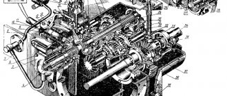
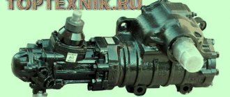
Gearbox of the MTZ 80 tractor
To switch the speed mode, the Belarus MTZ-80 models are equipped with a 9-speed 2-band gearbox equipped with a high-quality reduction gearbox. The presence of such a gearbox allows the tractor to move at any of 18 forward and 4 reverse speeds.
If necessary, the unit can be equipped with a creeper. The rear axle is controlled, depending on the tractor modification, by a mechanical or hydraulic drive. Tractor models that came off the assembly line in recent years of production are equipped with a hydraulic gearbox.
Chassis of the MTZ-82 tractor: main elements and their purpose
Structurally, the chassis of this model is made in the form of a trolley, consisting of assembly units, assemblies, mechanisms and individual parts intended for the movement of agricultural machinery: wheelbase, non-driving axle, frame (base where all structural elements are assembled).
From the front, the frame is equipped with cylindrical springs, which are located in the king pins of the front axle. The semi-frame consists of 2 spars and a durable metal beam secured with bolts. Brackets are attached to the rear of the side members by welding, connecting this structure to the clutch mechanism housing. The front beam is used to install the shutters of the power unit, main control wheels, engine support, oil and water radiators.
The front-wheel drive attachment from the gearbox is connected to the front axle. This makes it possible to ensure synchronous rotation of all wheels regardless of the speed of the vehicle.
The non-driving front axle MTZ-82 is the support of the front part of the agricultural machinery and, together with the RU (steering) mechanism, ensures the directed movement of the tractor through the front wheels.
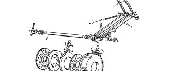
Considering the design of the Belarus tractor, we should dwell in more detail on the design of the front axle, consisting of the following elements:
- Pipes.
- Disc springs.
- Locking pin;
- Bushings and axle shaft.
- Swing axis.
- Disk.
- Hub.
- Rim.
- Half frame beam.
- Suspension springs.
- Visor (protective).
- Bridge beam.
- Half shaft.
- Terminal bolts;
- Brackets.
- Hub oiler.
- Inserts.
- Threaded plug.
- Case.
- Support washer.
- Sleeve.
- Cap.
- Thrust bearing.
- Ball pin.
- Fastening elements.
The bridge beam is located between the 2 eyes of the half-frame beam and is connected to it through the rolling axis. It is also connected to the tubes of the steering axles of the guide wheels and the steering linkage.
The pipes are inserted into the front axle beams, and 2 brackets are welded to them. The pipes are clamped with two terminal clamp bolts (each). A special feature of the pipe design is the presence of 6 through holes in them, which are located 50 millimeters from one another. They are used to accommodate the pin that adjusts the track width. It is carried out by moving the retractable pipe in relation to the beam.
The articulated joint allows the bridge beam to swing vertically (within 10 degrees) and thanks to this allows the front wheels to adapt to the terrain, as well as significantly soften the impact of road unevenness on the tractor frame. To prevent changes in position and rotation, the rolling axis is locked with a pin.
The structural elements of the steering axle are the axle shaft and the king pin. The latter is pressed into the corresponding hole on the axle shaft, and is also welded at the bottom. The shaft rotates on 2 bushings, which are located in the cam bracket. The lower bushing is placed in the hole of the bracket and screwed with two bolts, and the upper bushing is pressed into it.
The transmission of vertical loads of equipment to the ground surface is carried out through wheels with tires. In addition, the drive wheels convert the power of the power unit, transmitted to them through the transmission, into forward motion, thus acting as a propulsion device.
Structurally, the wheel consists of a one-piece steel rim and a rigidly attached disk and rubber tire filled with air or liquid. The latter is fixed on the wheel rim, which acts as a base. The wheel is attached to the hub using a disc.
The hub is made of cast iron and is made in the form of a casting, with a bore for installing bearings and a flange into which bolts are pressed for fixing the wheel rim. The hub rotates on 2 tapered bearings (roller). The outer races are pressed into the bores, and the inner races are placed on the axle shaft. The bearings are fixed using a nut that is screwed onto the axle shaft (threaded connection). To prevent the washer from turning on the axle shaft and the nut from being unscrewed, a special washer with a tendril that fits into the groove is installed between it and the bearing.
The load from the frame to the front wheel is transmitted through the spring and bracket, first to the ball bearing, and then through the washer and the steering axle shaft.
In MTZ-82, a ring is welded to the rear wheel disks, where they are attached to the hub. This increases their strength and strengthens the structure. The front wheel disks are secured using bolts, with which they are screwed to a bracket welded (to the rim).
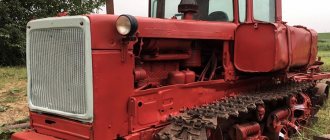
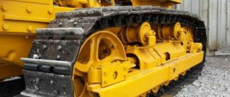
Chassis of the MTZ-80 tractor
The MTZ-80 unit can be wheeled or tracked. The MTZ-80 wheeled tractor is equipped with rear drive wheels, which receive the force generated by the motor through a transmission. In the design of the MTZ-82 modification, the leading axle is the front axle, which is driven by the transmission and transfer case.
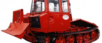
MTZ-80 tractors, which are equipped with tracks, have better stability when moving on loose soil, and can easily overcome obstacles in the form of ravines, wetlands or slippery ice.
Track parts
At the track chain link, the eye holes, treads, lugs, and lanterns wear out at the points of contact with the teeth of the drive wheel. Deformed links are straightened in a hydraulic press, small cracks are welded.
Wear of the lugs is allowed up to a wall thickness of 3 mm, and wear of the lantern - up to 7 mm. Worn fingers are replaced with new ones.
When restoring track links of tractors of traction class 3, the most widely used methods are plastic deformation (compression), pouring with liquid metal, and electric arc surfacing. The best quality indicators are provided by the method of plastic deformation using multi-section punches on specialized lines.
Using an electric arc, a carbon electrode is used to burn a technological hole in the eye wall on the side of greatest wear, a technological rod is inserted into the eye and it is sealed on both sides with refractory clay. The metal is melted in crucibles or using high-frequency frequency and poured into the eyes through technological holes. It fills the cavity of the eye and, crystallizing, forms a liner, held due to the unevenly worn surface of the eye and metal frozen in the technological hole.
The eyelets of the links are also restored using the forging and welding method. Worn lugs are heated in a furnace to a temperature of 800-900°C, cut and pressed onto a mandrel with a hammer. The joint is welded using electric arc welding and a layer of metal is deposited to obtain normal wall thickness.
When repairing the track chain of the T-130 tractor, worn bushings and pins are not restored. Bushings and pins with one-sided wear are rotated 180°, and if they are worn on both sides, they are discarded. If the holes for the bushings and pins are significantly worn, the links are replaced. The running track of the link is restored by surfacing. Worn shoe lugs are fused under a layer of flux in special devices. The track chain is disassembled and assembled using a hydraulic press.
Excavator track chain links experience wear on the side tracks, ridges, and eye holes.
Running tracks worn by more than 6 mm are restored by automatic surfacing under a layer of flux. The worn surfaces of the ridges of the links are manually fused using templates using OZN-250U or OZN-ZOOU electrodes. After surfacing, the ridges are cleaned with a grinding wheel. Links that have significant wear on the holes in the lugs are discarded.
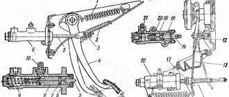
Brake system of an agricultural machine
The main braking mechanism in the design of the MTZ-80 unit is a disc brake system. Dry brakes are provided in the shaft gears on the right and left sides of the front and rear axles.
Additionally, to stop the tractor, it is equipped with a parking brake. It is designed to hold equipment in areas located at an angle. Also, for long stops on slopes and inclines, the tractor design includes an auxiliary brake mechanism.
Kun for Belarus MTZ-82
We recommend reading our other articles
- Continuous tillage cultivator
- Cultivator Viking 585
- Seeder John Deere 455
- Plow PLN
The simplest and most common type of special attachment, of course, can be called KUN on the MTZ-82. KUN is a universal mounted hay hauler, which is essentially a tractor front-end hydraulic loader for moving, lifting and lowering various large loads. KUN on the MTZ-82 tractor is used not only for moving and storing hay, but also for transporting bulk and bulk cargo. They are modernized and manufactured independently; a prominent representative of the tuned KUN is the bucket.
Photo of MTZ 82 with KUN
Most often, the PKU-0.8 device is mounted on the MTZ-82 as a KUN; the main technical characteristics are as follows:
- weight of lifted loads up to 800 kilograms;
- high-rise ceiling up to 3.5 meters;
- weight of the mounted loader up to 700 kg;
- maximum travel speed with load up to 20 km/h.
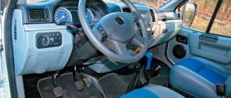
Cabin and unit interior
The Belarus MTZ-80 tractor is equipped with a spacious cabin. It is attached to the power frame using rubber shock absorbers, which effectively suppress noise from the operating transmission and tractor engine. The comfortable driver's seat can be adjusted in height.
The internal surfaces of the cabin of the MTZ-80 unit are finished with thermal and noise-absorbing material. There are rubber mats on the floor that prevent the driver's feet from slipping off the pedals. The interior of the tractor cabin will be clearly demonstrated in the photo.
Welding and running-in of chassis units
For assembly, special stands and devices are used. Tractor carriages of traction class 3 are assembled on the same stand on which they were disassembled (OPR-1402M). Tapered axle bearings are adjusted by changing the thickness of the shim set. When the bearing clearance is correctly adjusted, the axle rotates tightly by hand. The support rollers are installed in pairs, taking into account their actual dimensions. This is explained by the fact that there are wide deviations in the diameter of the rollers. Installing them in pairs with a minimal difference in diameter increases the life of the chassis, since it makes it possible to evenly distribute the load on the support rollers and thereby reduce wear on the track rollers and track links.
After assembly and filling with lubricant, the carriages are run in to identify assembly defects and run-in of sealing rings and other parts for 15 minutes at a roller rotation speed of 150 min-1. During break-in, check for oil leaks and reliability of parts fastening.
The caterpillar bogies of the T-4, T-100M and T-130 tractors are assembled on a special stand or stand. Assembly begins with assembling the frame, installing the spring shock absorber and road wheels. For the trolleys of the T-100M and T-130 tractors, single-sided rollers are installed at the edges and in the middle, with double-sided rollers between them. The trolleys of the T-4 tractor must have double-sided rollers installed first, third and fifth along the tractor, and single-sided rollers must be installed on the second, fourth and sixth ones. After installing the track rollers, a ruler (rail) is placed on their treadmills. The gap between the ruler and the minimum diameter roller should not exceed 1.5 mm. It is allowed to install gaskets under the roller axle in the places where it is attached. The displacement of the rollers relative to the longitudinal axis of the trolley should not exceed 1.5 mm. After assembly, the carts are tested on a special stand. Tractor tracks of traction class 3 are assembled manually in workshops on special stands. The connecting fingers are installed with their heads on the outer side of the links. On the opposite side there are washers and cotter pins. At specialized enterprises, for assembling track chains, they use a hydraulic stand OR-7748, which ensures pressing in (pressing out) of the pins and discrete movement of the track one step at a time.
When assembling the tracks of the T-4, T-100M and T-130 tractors, a PB-002 press and a special device are used. The bushings of the track fingers should protrude by 6 mm after pressing the links. The bushings of the closing pins protrude above the outer ends of the links by 0.5 mm. The tightening torques for the shoe nut bolts should be 140-150 Nm.
Tractor MTZ-80 - technical characteristics and areas of application
A well-thought-out design and good balance of the Belarus MTZ-80 unit allowed the unit to acquire excellent technical characteristics. These include:
- power – 80 l. With.;
- cylinder working volume – 4.75 l;
- number of speeds – 18 forward/4 reverse;
- minimum ground clearance - 47 cm;
- fuel consumption under average loads – 230 gkW/h;
- weight – 3.77 t.
The dimensions of the MTZ-80 tractor are quite modest. The length of the unit is 3.93, width – 1.07 and height – 2.74 m.
The high power of the agricultural unit allows it to be used to perform the following tasks:
- for working with a plow for effective plowing of virgin soil and heavy clay soils;
- for harrowing and preparing rows before planting;
- for planting tuber crops and sowing seeds;
- for hilling beds, watering, distributing fertilizers and harvesting crops;
- for cleaning the garden after harvesting - mowing grass, making hay, cultivating the soil before the winter season;
- for transporting crops;
- for clearing the local area from snow and ice, as well as sweeping the roadway.
Very often in factories and warehouses, a kun is used in tandem with this popular unit, which allows the tractor to be used as a universal loader.
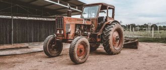
Description of the Belarus model
Simplicity + reliability - the main qualities necessary for equipment for any purpose are perfectly embodied in the Belarus MTZ-80 tractor. The machine is designed in a characteristic semi-frame design system - a front-mounted engine, driving rear wheels of a larger diameter than the front ones.
MTZ-80.1
Technical characteristics of the Belarus 80.1 tractor
| Engine | |
| Type | diesel without turbocharging, with direct fuel injection |
| Power, hp/kW | 81,6/60 |
| Model | D-243 |
| Rated crankshaft rotation speed, rpm. | 2200 |
| Number of cylinders, pcs. | 4 |
| Cylinder diameter/piston stroke, mm | 110 x 125 |
| Working volume, l | 4,75 |
| Maximum torque, Nm | 298 |
| Torque reserve factor, % | 15 |
| Fuel tank capacity, l | 130 |
| Transmission | |
| Transmission | mechanical, stepped |
| Clutch | dry, single disc |
| Number of forward/reverse gears | 18/4 |
| Travel speed, km/h: forward/backward | 1,9–34,3/4,09–9,22 |
| Rear PTO: | |
| independent I, rpm | 540 |
| independent II, rpm | 1000 |
| synchronous, rpm path | 3,4 |
Preparing the MTZ-80 tractor for work - a note for beginners
Each model of MTZ-80 tractors leaves the factory fully equipped for further work. Each unit comes with a full set of spare parts, tractor driver’s tools, detailed operating instructions and additional accessories. However, before starting the tractor, the farmer still has to perform a number of procedures aimed at facilitating the start of the engine and other mechanisms of the agricultural machine. Their list includes:
- Before starting, you need to thoroughly wash the tractor;
- After this, you will need to remove the standard batteries and bring them into working condition;
- Next, you need to remove the protective polyvinyl chloride covers;
- Then you will need to install the drain valves of the standard radiator cylinder block on the tractor;
- In accordance with the lubrication table, you need to lubricate the rubbing components and mechanisms of the tractor;
- Next, you need to fill the fuel tank with settled fuel;
- After this, you need to fill the engine cooling system with clean water;
- Next, you need to check the pressure in the tractor tires, as well as in the hydraulic system pipes;
- At the end, you will need to install charged batteries and widen the tractor track to 140 cm. The video will clearly demonstrate the preparation of the Belarus MTZ-80 tractor for work.
Completing all of the above procedures before each cold start of the engine will extend the life of the MTZ-80 tractor and eliminate its breakdown. Thanks to this, repairs to the unit will need to be performed much less frequently.
Checking the air pressure in your tires is a critical operation that affects the longevity of the tire and its grip on the ground.
When the tire operates with reduced air pressure, the middle part of the tread (Fig. 82, a) is somewhat unloaded, bending inside the tire, which causes the material tension to increase in the outer zones of the tread. Over time, the cord threads of the inner layer peel off from the rubber, which leads to their fraying and tearing.
When working with reduced pressure, the contact of the lugs with the soil decreases, which, in turn, increases slippage and wear of the edges of the treadmill (star lugs), while its middle part remains almost unworn.
Increased air pressure reduces tire deformation (Fig. 82.6) and, accordingly, its contact area with the road. As a result, the wear of the tread (toe bars) in its middle zone accelerates and wheel slippage increases.
Rice. 82. Scheme of immersion of tractor tire lugs into the soil at different internal air pressure: a - insufficient; b - excessive; in - normal.
In addition, the tension in the carcass cord threads increases, which accelerates the process of cord “fatigue” and leads to premature rupture of the carcass.
When the air pressure in the tire corresponds to the manufacturer's recommendations, the lugs enter the soil more smoothly (Fig. 82, c), the tires wear out more evenly and more slowly, which significantly increases their service life.
To check the pressure, clean the valve from dirt, unscrew and remove the cap. Press the tip of the tire pressure gauge onto the valve and use its reading to determine the tire pressure. If it does not meet the norm, then bring it to the required level.
It should be remembered that for different types of work the tire pressure is not the same and also depends on the implements with which the tractor works.
For this purpose, place the tractor with the machine-implement on the scales as shown in Figure 83. Determine the force of gravity of the tractor falling first on the rear wheels, and then (after moving the tractor) on the front ones. Dividing the results by 2, you get the pressure applied to each wheel.
Determination of wear of lugs and ribs of pneumatic tires. To determine the wear of the tread pattern or lugs of a pneumatic tire, clean the tread of dust and dirt. Next, inspect the treadmill and use your eye to identify the area with the most wear, where you should mark a chalk area where you need to measure.
Rice. 83. Weighing a tractor on truck scales: 1—scales; 2 - tractor.
Rice. 84. Determination of wear on tire lugs: a and d - measurement locations; b - measurement with a depth gauge; c - measurement with a device; 1 — depth gauge; 2 - device.
Using a depth gauge (Fig. 84.6), which provides an accuracy of ± 0.1 mm, or a special device (Fig. 84, c), measure the areas of greatest wear, except for the locations of half-bridges or ledges at the base of the tread pattern.
Measure the height of the lugs in the center (Fig. 84,d) or in places least distant from the center of the treadmill, but not along the ledges at the base of the lugs and not along the half-bridges.
If the tractor operates at a speed less than 30 km/h, the load on the tires can be increased to the values specified in Table 29.
The maximum wear of the lug, after which the tire must be removed from the tractor and sent for repair, will be more than 80%. At the same time, slipping of the drive wheels increases to 20...28%, productivity decreases by 10...12% and fuel consumption increases by 6...8%.
After determining the wear of the lugs, compare the degree of wear of the tires of the right and left wheels (the difference is no more than 6%). Otherwise, this may lead to misalignment and deformation of the axle shafts and wheel rims, as well as violation of the alignment angles of the front wheels. These deviations should be identified and corrected.
Tractor wheel chambers are filled with liquid to increase traction.
In summer, fill 3/4 of the chamber volume with clean water. At ambient temperatures below +5 °C, use a solution consisting of 25 parts (by weight) calcium chloride (CaCL) and 75 parts water. This solution has a freezing point of up to -32 °C.
If you pour liquid, for example, into a wheel size 12-38 by 3/4 of the volume, then its grip will increase by 1700 N.
To pour liquid into the chamber, you need to lift the wheel (Fig. 85, a) with a jack until it comes off the ground, connect the tip of the device to the air valve and, opening the access of liquid, fill the chamber. After this, you should inflate the tire to the required pressure.
To remove liquid from the chamber, you need to put the valve in the lower position, remove the spool and drain the bulk of the liquid. The remaining part of the liquid can be removed as follows: pump air into the tire to a pressure of 0.1...0.15 MPa, remove the sleeve with spool from the valve and in their place insert a tube with a rubber seal into valve 2 (Fig. 85.6). The liquid will be squeezed out by the internal air pressure in the tire.
Rice. 85. Increasing the traction force of the tractor: a - filling the chambers of the tractor driving wheels; b - removal of liquid from the chamber; 1 — rubber seal; 2 - valve; 3 - tube.
Rice. 87. Putting on and removing tires from the rim: a, b, c, d, e and f - sequence of operations.
Installation of dual drive wheels. When operating the tractor on waterlogged soils and reclaimed peat bogs, it is advisable to install dual wheels to reduce slipping of the driving wheels of the tractor.
As an example, Figure 86 shows the connection of dual wheels on the MTZ-80 and MTZ-100 tractors. The wheels should be installed so that the bulges of the discs are located against the spacers.
Placing tires on and off the rim. Thoroughly clean the wheel rim from dirt and corrosion and determine which side of the tire should be put on the rim, so that after placing the finished wheel on the tractor, the direction of its rotation coincides with the arrow on the tire (Fig. 87, a).
Place one bead of the tire over the edge of the rim, to do this, first put part of the bead on the rim, then use the blades to pull the entire bead.
Powder a dry, clean inner tube with a thin layer of talc, place it in the tire (Fig. 87.6), straighten it thoroughly, and insert the valve into the hole in the rim.
Rice. 86. Installation of dual drive wheels of the MTZ-80 tractor: 1 - disks; 2 — spacer.
Place part of the second bead of the tire on the side opposite the valve (Fig. 87, c), and, making sure the valve is in the correct position using the paddles, tighten the rest of the bead of the tire. End the tugging at the valve (Fig. 87,d).
Inflate the tire with air to a pressure exceeding the norm by 50... 100 kPa so that the tire fits well to the rim, and then reduce the air pressure through the valve to the norm.
To remove the tire, release the air from the chamber by unscrewing the spool from the valve.
Slide both beads of the tire from the rim flanges into the rim recess on the side opposite to the location of the valve.
Place two mounting blades between the tire bead and the rim on both sides of the valve at a distance of 10 cm and pull first the part of the bead near the valve over the edge of the rim (Fig. 87, e), and then the entire bead.
Push the valve into the rim and then remove the tube from the tire. Turn the wheel 180°, move the recesses of the tire bead rim to one side, insert the blades on the other side and remove the rim from the tire (Fig. 87, e).
Checking and adjusting the front wheel bearings of universal row-crop tractors. Brake the rear wheels of the tractor with the parking (mountain) brake and lift the front wheel with a jack so that it does not touch the ground.
Attach the indicator head to the front wheel axle so that its rod is in contact with the surface of the wheel hub, and set the scale zero against the arrow. By moving the wheel along the axle axis with your hands, determine the clearance in the bearings. The maximum permissible clearance in the bearings is 0.25 mm.
Rice. 88. Checking the front wheel bearings (a) and adjusting the guide (b) and drive (c) wheels: 1 - nut; 2 — cap; 3 - gear; 4 - cover; 5 — body; 6 - screws; 7 — adjusting rings.
If there is no indicator, then check the clearance by rocking the wheel with your hands as shown in Figure 88a. If it is determined that the bearings have increased clearance, they should be adjusted.
Adjusting the wheel bearings of a tractor with a 4K2 wheel arrangement. Remove the cap (Fig. 88.6) with the gasket, then check the ease of rotation of the wheel. If you find jamming during rotation, find and eliminate the reason that caused it.
Unscrew the nut and, turning the wheel (to ensure correct placement of the rollers in the cages), tighten it until the force to rotate the wheel by the tread is about 45 N (no more).
Tighten the nut, replace the hubcap, lower the wheel and remove the jack.
In the same sequence, check and, if necessary, adjust the bearings of the second front wheel of the tractor.
Adjusting the wheel bearings of a tractor with a 4K4 wheel arrangement (using the example of the MTZ-82 tractor). With proper adjustment and operation of the tractor, an axial play of more than 0.3 mm appears in the bearings after 5...6 thousand hours of operation, and it is eliminated when repairing the tractor. However, if during inspection before the specified period a gap is found that exceeds the norm, then eliminate it in this sequence.
Unscrew the nuts and remove the disc along with the pneumatic tire. Drain the oil from the front wheel gearbox.
Remove the cover from the housing (Fig. 88, c) along with the driven gear and bearings.
Tighten the screws as far as possible. If they can be tightened, this means that the cause of the increased gap is insufficiently tightened screws. After this, put the removed part of the gearbox in place and check the axial clearance again. If the gap is within the normal range, secure the screws 6 with a bending plate, replace the removed parts and fill the gearbox with oil.
If, after tightening the screws, the gap in the bearings exceeds 0.2 mm, then again remove the cover with the driven gear and adjusting rings 7 and sand the end of one of them with sandpaper to the desired value. After assembly, check the gap, secure screws 6 with a bending plate and fill the gearbox with oil.
Open joint track maintenance.
When a caterpillar tractor operates, part of the engine power is spent on friction in the hinges of the track chains and in the engagement of the chains with the drive sprockets. This is affected by the degree of tension of the tracks. Excessive tension increases friction and wear of parts. Insufficient tension increases power loss due to track runout, and in some cases leads to track jumping.
Rice. 89. Checking the condition of the caterpillar track of tractors: a _ T-74, DT-75M and T-150; b - T-54S and T-70S.
Wear on the movers of a crawler tractor depends not only on the degree of tension of the tracks, but to a large extent on the type of soil on which the tractor operates. For example, wear on tracks on sandy soils is almost 2 times higher than wear on black soils over the same period of time.
When the track parts wear out, its pitch increases, which weakens its tension and in turn causes increased wear on the drive sprocket.
Worn track fingers cause accelerated wear of the link eyes, and uneven wear of the right and left tracks disrupts the straightness of the tractor, which significantly tires the tractor driver.
To increase the service life of the caterpillar, it is necessary to carefully and promptly monitor its wear, as well as its correct tension.
Checking the tracks of the T-74, DT-75M and T-150 tractors is carried out on a horizontal solid platform. The caterpillar must first be thoroughly cleaned of dirt and washed with water.
The first check after putting a new tractor into operation is scheduled after 600...700 hours of work on sandy soils or after 1200...1400 hours of work on black soils. To do this, measure the length of 10 links (both tracks) located under the tractor (Fig. 89, a). The length of 10 links of both tracks must be the same and not higher than 1750 ... 1760 mm. If the size is within the specified limits, but differs by 10 mm for different tracks, then swap them.
The second check is 500 hours after the first when working on sandy soils or after 1000 hours on chernozems. The length of 10 links should not exceed 1810...1820 mm, but in this case it is necessary to replace the track pins with new ones and, in addition, swap the tractor drive sprockets.
In case of through wear of the links along the tarsus, the tracks must be rotated 180° and swapped.
Checking the tracks of the T-54S and T-70S tractors. The procedure for checking the degree of wear is the same as described above, with the only difference that for these tractors the length of five links should be measured (Fig. 89.6).
For tracks with a width of 300 mm, when the length of five links increases to 920...930 mm, it is necessary to replace the pins with new ones. The second set of fingers must be installed when the length increases to 930...940 mm and the third - up to 940...950 mm.
For tracks with a width of 200 mm, when increasing the length L of five links from 880 to 920 mm, cut the locking brackets, knock out the pins and press out the bushings. After this, turn the bushings 180° and press them into the old places. The sleeve groove should be in its original position. Collect the caterpillar. When unpressing and pressing bushings and locking pins, use special devices consisting of a pin, a conical guide bushing and a mandrel for locking pins, supplied with the tractor spare parts.
After the second side of the bushings wears out, they should be replaced with new ones.
Place track chains on the tractor so that the links on the lower branch are positioned with the side with two (for a chain 200 mm wide) or three (for a chain 300 mm wide) eyelets facing the direction of forward movement of the tractor. In this case, the heads of the fingers must be outside the tractor.
Checking and tensioning tracks. Clean, wash the tracks and place the tractor on a flat, hard surface so that the track fingers are above the support rollers (before stopping, the tractor should only move forward in order to loosen the upper branches of the tracks).
Place the rack on the track lugs and, using a ruler, measure the distance in the middle between the support rollers or the guide wheel and the support roller (Fig. 90, a).
Loosen the locknuts (Fig. 90.6), except for the T-150 tractor, and by rotating the adjusting nut or shock absorber body or pumping oil with a lever-plunger syringe, tighten the tracks.
After adjusting the tension, tighten the loosened locknuts and lubricate the threads of the tension bolt with US grease.
If, during tension, the caterpillar of the T-150 tractor is very stretched and the cranked axis of the tension wheel comes into contact with the stop mounted on the frame, and is no longer able to tension the caterpillar to the required size, then further injection of grease is unacceptable, as this may lead to tensioner failure. Unscrew the safety valve, move the wheel back (in this case, grease will be squeezed out through the hole from which the valve is unscrewed). Then disconnect the track, remove one link from it. Next, connect the track, put the valve in place and, pumping grease into the hydraulic cylinder, tension the track.
Rice. 90. Checking (a) and tensioning (b) tracks
Rice. 91. Scheme for rearranging carriages of a caterpillar tractor.
Rearranging suspension carriages. Every 1900...2000 hours of tractor operation, rearrange the suspension carriages in a cross pattern (Fig. 91), which promotes uniform wear of the carriage support rollers.
Specifications
The engine power supply system is direct fuel injection into each cylinder. The tractor's power system is designed to accurately supply fuel to the engine chamber.
Cooling is forced, liquid, closed type. The gas distribution system has a lower camshaft, but the valves are installed in the cylinder head.
The lubrication system is a combined one and serves to lubricate some engine components with lubricants under pressure to reduce wear on the rubbing parts of the engine. All systems and mechanisms of the power plant are driven by gears from the crankshaft.