Device, diagrams, repair
Hydraulics of the T-40 tractor: diagram and malfunctions
The hydraulics of the T-40 tractor are divided into a power steering system and a separate hydraulic mounted system.
These systems operate from one pump, but have different purposes. The hydraulic linkage system is used to operate the tractor with trailed, semi-mounted, mounted implements and machines. The power steering system is designed to reduce the force applied to the steering wheel. Device and circuit
The T-40 hydraulic system consists of a gear pump, a hydraulic tank with a filter, a flow division valve, a hydraulic distributor, a hydraulic booster, shut-off devices, pipelines and hoses, remote and main hydraulic cylinders, and breakaway couplings.
T-40 hydraulic diagram: 1 - hydraulic tank; 2 - pump; 3 — flow division valve; 4 - spool; 5 — spool spring; 6 - filter; 7 — power steering; 8 — hydraulic distributor; 9 — main hydraulic cylinder; 10 — remote hydraulic cylinders.
Operating principle
Oil from the hydraulic tank is supplied to a gear pump, which forces it into the distribution valve. The valve divides the oil flow into two branches: one goes to the hydraulic booster, and the second goes to the hydraulic distributor of the hydraulic lifting system. The hydraulic distributor supplies a flow of oil either to the hydraulic tank through the oil return line, or to the hydraulic cylinder, or through the rear and side outlets directly to the hydraulic drive of agricultural equipment.
Hydraulic system malfunctions
What to do if the T-40 hydraulics do not work?
The attachment does not rise to transport position:
1. Jamming of the distributor bypass valve - disassemble and wash the bypass valve.
2. Safety valve contaminated - Disassemble and clean the valve assembly. Adjust it to a pressure of 130-140 kgf/cm².
The implement rises too slowly or jerkily:
1. There is not enough oil in the hydraulic tank - add oil to the top mark on the dipstick.
2. Air leak in the suction line - tighten the suction line connections.
3. Air leakage through the oil seal of the pump drive gear - the oil seal must be replaced.
4. Increased leakage in the pump - the pump should be replaced.
The distributor handles do not automatically return to the neutral position from the working position:
1. The safety valve spring is weak - adjust the safety valve.
2. The distributor spool booster spring is too tight - it is necessary to adjust the response pressure to 100-125 kgf/cm².
Hydraulic system pump drive T-40
The pump drive is made in the form of a ball clutch, which allows you to turn the pump on or off at low crankshaft speed. The hydraulic pump drive is turned off when using the tractor as a stationary machine, when starting the engine in winter, as well as in the event of a fault in the hydraulic booster or hydraulics.
T-40 oil pump drive: 1 - hydraulic system pump; 2 — axis of the pump activation lever; 3 — pump drive housing; 4 - ball; 5 — pump roller bushing; 6 — ball bearings; 7 — pump drive gear; 8 — front sheet; 9 — drive gear axis; 10 — pump clutch; 11 — lock handle; 12 — pump activation lever; 13 — pump switch.
If the pump turns off spontaneously during operation, loosen the fastening of the drive lever and, by turning it with further tightening of the bolt, find a position that facilitates stable turning on and off of the hydraulic pump.
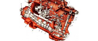
T-40 engine
Engine structure of the T-40 tractor: piston, crankshaft, cylinders
Power transmission
Design and operation of the power transmission of the T-40 tractor
Supply system
Design of the T-40 tractor power system: nozzles, fuel injection pump, etc.
Electrical equipment
Electrical equipment T-40: diagrams and device.
Hydraulics
Hydraulic system: malfunctions and repairs.
Source
problems with the T-40AM tractor
Questions can only be asked after registration. Please login or register.
Explain the reason for the boiling of the working fluid in the hydraulic system of the T-40 tractor and the operating principle of the flow valve. Thanks in advance
Check if one of the distributor levers is engaged, also check if the bypass valve on the distributor is stuck
wash the oil filter; it is on the hydraulic tank; if the mesh is clogged, oil then begins to pass through the emergency valve (a tube with a spring and a ball)
The jester knows the principle of operation of this flow distribution valve. Here on the forum I read about tandem pumps. I will look for and install it, otherwise there will be trouble with this steering one.
The jester knows the principle of operation of this flow distribution valve. Here on the forum I read about tandem pumps. I will look for and install it, otherwise there will be trouble with this steering one.
If you are interested, the operating principle of the flow division valve. Files: kl.jpg
_______________________________________ “Do what you can, with what you have, where you are.” Theodore Roosevelt ©
and in your own words, if possible, otherwise something is confusing
and in your own words, if possible, otherwise something is confusing
Damn, this is a question worth a hundred points, I’ll try my best.
When the steering wheel is not turned and the hydraulics are not used, the oil passes through the power steering and distributor with virtually no resistance. In this case, the pressure in the chambers under and above the spool is the same, and it hangs in the middle, supported from below by oil pressure and from above by spring pressure. When the steering wheel was turned, the oil passage in the power steering was blocked and the pressure in the chamber above the spool rose, it is added to the spring force and the spool is pressed down. When the spool went down, it blocked the outlet to the hydraulic distributor with its body. It will remain in this position as long as the steering wheel rotates. As soon as the steering wheel was stopped, the pressure above and below the spool was equalized again and it returned to the middle position. When the hydraulic distributor lever was pressed, the oil path in it was blocked and the pressure began to increase under the spool, the pressure that was there initially is added to it, and their sum, overcoming the spring pressure, lifts the spool up. At the same time, he blocks the exit to the steering wheel with his body. When we simultaneously turned the steering wheel and turned on the lever on the distributor, the pressure rose equally both above the spool and below it, it will become equally high in both places. In this case, the spool also hangs in the middle, supported from below by the sum of the increased and initial pressure, and from above by the sum of the increased pressure and spring pressure.
It turned out to be even more confusing than in the book.
_______________________________________ “Do what you can, with what you have, where you are.” Theodore Roosevelt ©
Source
Adjusting the hydraulic booster mechanisms of the T-40 and T-40A tractors
Steering is one of the most important mechanisms in any driven vehicle. It is he who is “responsible” for turning the guide wheels and, therefore, for all maneuvers of the tractor. It is very important to ensure that it is in good working order and accurately responds to the operator’s manipulations. The steering of the T-40 tractor consists of several elements: a steering column and a wheel located in the cabin, as well as a shaft and universal joints. To facilitate control, the T-40 is equipped with a power steering system - a hydraulic booster with a bipod.
How is a three-way valve checked?
Malfunction of the device affects the operation of the gas boiler as a whole. For example, if the coolant supply is insufficient, the gas boiler may simply turn off due to overheating. Or, a malfunction of the three-way valve may be accompanied by a lack of proper heating temperature of the coolant in the heating system.
In any case, the device needs to be checked for functionality. At the same time, to carry out diagnostic measures, the gas boiler control device, as a rule, has to be dismantled. Dismantling is relatively simple, so such work can easily be done on your own.
Step #1 - Valve Actuator Check
Next, we will consider the verification process step by step, starting with checking the drive. Let's consider the features of diagnosing valves with different types of drive.
Diagnostics of the three-way valve electric drive
The valve stem is traditionally controlled by an electric actuator. Therefore, the integrity, availability of power, and operability of the electric drive should be checked first.
The integrity of the external part is checked visually through careful inspection, and the presence of power and the integrity of the internal mechanism are checked with appropriate instruments.
The drive and all elements of this part of the structure are usually diagnosed with an electrical tester. This device can check both the integrity of the circuits and the presence of supply voltage. When the supply voltage is applied/disconnected, a serviceable drive should demonstrate a working process - movement of the valve rod pusher.
It is permissible to check the operation of the electric drive by directly connecting the mechanism to the electric current network, using the connector that comes with the drive. This point is clearly illustrated in the video located at the end of the article.
Steering column design
The steering column of the T 40 tractor consists of the following elements:
Spring washers exert load on the idler wheels. When the steering wheel rotates, pressure increases in the piston cavity. To prevent excessive compression of the springs, stops are provided. When turning the nut, you act on the spring washer, which increases the force on the steering wheel.
The hydraulic booster on the T-40 consists of a housing, a piston, a screw, a distributor, a bipod shaft, and front and rear covers. The T 40 power steering circuit is presented in any operating device.
Power steering tractor T 40 Operating principle:
Operating principle and hydraulic diagram of the T-25
The hydraulic system of a tractor is a set of mechanisms that perform their task using the kinetic and potential energy of various fluids. In the T-25 tractor it consists of the hydraulics itself and the rear canopy.
The main purpose and function of the T25 hydraulics is to raise or lower any mounted equipment (plow, cultivator, mower, seeder, etc.). The hydraulic system itself consists of an oil pump and tank, as well as a power cylinder and distributor. All fluid is transmitted through special oil lines that connect various hydraulic components and help drain the oil back to the expansion tank.
The main and only working fluid of the hydraulic system is diesel oil. It is this that fills all the internal spaces of the tractor hydraulic lift (expansion tank), which is located in the rear part.
When adding diesel oil, it is first purified in the oil filter. If the filter is clogged, the system has a special diverter valve through which it can enter the tank, bypassing the cleaning process. You can check the oil level in the system using a special dipstick, which indicates the permissible minimum and maximum levels.
Scheme of operation of the hydraulic system of the T-25 tractor
Operating principle of T-25 hydraulics
The main pressure in the system is generated by an oil gear pump, which supplies oil to the distributor under high pressure and takes it back to the tank.
The dependent position of the distributor spool forces oil to flow up or down into the hydraulic cylinder cavity. The oil drains from the distributor back into the expansion tank.
Balancing underfloor heating, how to set up the collector
Setting up a heated floor raises questions because there are many variations in hydraulic designs. There are complex manifolds with flow meters, and there are also homemade ones, welded from polypropylene... Several methods are known for acceptable adjustment of a heated floor, the simplest of which is using a balancing valve, guided by subjective sensations of “hot or not hot” pipe, “normal or abnormal” temperature warm floor.
But the usual approach is different - each heated floor circuit is adjusted using a rotameter in accordance with the calculated coolant flow.
But how to configure the underfloor heating collector itself? Many manifolds are equipped with a two-way valve with a thermal head, as well as a bypass between flow and return, which is equipped with a tuning valve, it needs to be balanced... You may find manifolds with a three-way valve, or other options...
Three way valve operation
A three-way valve mixes the two flows entering it, while another type separates them. The flow ratio and outlet temperature depend on the position of the plate. This is regulated by recessing the rod, which in turn is pressed by the thermal head.
Thermal heads are used with a remote sensor installed on the pipeline, controlled by the temperature of the resulting flow.
Thus, by installing a three-way valve at the entrance to the manifold, we can maintain the required coolant temperature in the heated floors, usually 35 - 45 degrees. Temperature adjustment often consists only of setting values on the thermal head. There is no need to balance the collector itself, only the circuit.
Why two-way valves are preferred over three-way valves
In a circuit with a three-way valve, the temperature of the coolant will depend too strongly on the position of the valve disc. Inaccuracies in the operation of mechanisms lead to significant unnecessary results. The scheme turns out to be not as reliable as with a two-way valve and bypass.
How does a two-way valve manifold work?
A two-way valve regulates the flow “more or less” depending on the recessing of the rod by the thermal head. It is installed at the inlet to the manifold on the supply side and regulates the proportion of hot coolant entering the manifold compared to what goes from the return to the supply through the bypass.
But this system requires preliminary adjustment of the flow ratio through the bypass and through the open two-way valve. The bypass is equipped with a setting valve for a hex key. It needs to be configured, but how correctly?
Power steering repair
Repairing a power steering is a complex procedure. It is no coincidence that on new tractors the power steering valve is equipped with a seal - intervention can lead to serious damage. However, on older tractors, repairs are usually carried out with your own hands, power steering T 40. Before you start adjusting the valve, you need to adjust the oil pressure in the system. To do this, you need to connect a pressure gauge to the discharge hose. After unscrewing the locknut, start the engine at maximum crankshaft speed. Oil pressure is adjusted by turning the bipod. Next, it is important to check the steering play. The maximum value with the engine and hydraulic pump running is 20°. If there are deviations, they must be eliminated by tightening the shaft and bipod connections. In addition, it is necessary to carefully examine the place where the shaft sector engages with the teeth and, if they are damaged, replace them.
Another important procedure is adjusting the side clearance and engagement of the shaft teeth. Produced in several stages:
Dismantling and assembling the steering control
Unlike power steering disassembly, column repair is accessible to novice mechanics. To disassemble the piston, press the pin into the rear nut, after which it will be possible to unscrew and remove the nut and spring washer. Then you need to push out the power steering screw and remove the spool. Reassemble the assembly in reverse order. All parts are first washed in clean diesel fuel, and the spool is lubricated with engine oil. Before starting work, it is recommended to read the instructions and watch training videos.
Installation Rules
Many tractor owners, having disassembled the unit, decide to convert it into a metering pump. This makes management even easier. Installing a double pump allows you to separately connect the tractor linkage, separately - the hydraulic cylinder and the steering metering unit.
Power steering diagram of the T 40 tractor
The complexity of such a modification lies in the fact that today there are no standardized mounting brackets for the metering pump and hydraulic cylinder. As a rule, the dispenser is placed closer to the cabin, at the exit point of the steering shaft cardan. You will need to make a homemade bracket and weld it above the fourth cylinder. In this case, it will be convenient to connect the hoses with fittings at 90 degrees.
Adjustment
The unit is checked and adjusted every 100 operating hours. It is necessary to inspect all parts and mechanisms for defects. Check:
Lubrication is carried out at the same time. Recommended lubricants are listed in the instruction manual. For example, cardan crosspieces are lubricated by injecting grease with a hand-held syringe until lubricant forms in the gaps.
Device, diagrams, repair
T-40 tractor hydraulic booster (power steering): design and repair
Power steering on the T-40 tractor to reduce the force on the steering wheel used by the tractor driver when making turns. The power steering is located in the front engine compartment of the tractor and is mounted on the front frame bar.
Power steering device
The hydraulic booster consists of a housing, a distributor, a piston, a screw, a bipod shaft, and rear and front covers. The housing contains a piston equipped with a through hole for installing a screw. The screw has a left-handed four-start trapezoidal thread onto which the rear and front nuts are screwed. Both nuts are secured with pins to prevent them from turning. The rear pin, installed in the holes of the rear nut and piston, is pressed by a spring. According to operating conditions, the power steering screw should not have axial movements. As a result, the bearing is fixed on the screw with a slotted nut, locked with a pin.
The switchgear kit includes: a hydraulically controlled spool, stops, piston, springs, rear and front nuts.
The piston has three teeth that engage with the teeth of the bipod shaft. During assembly, the middle tooth of the piston is inserted into the middle cavity of the sector. The gap in the engagement of the sector with the piston is adjusted using a special adjusting screw.
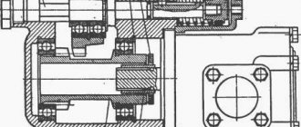
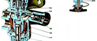
The device of the hydraulic booster of the T-40 tractor: 1 - bipod shaft; 2 — front cover; 3, 5 - nuts; 4 - ball bearing; 6 — front nut; 7 - spring washer; 5 - seal; 9 - piston; 10 - body; 11 — top cover of the housing; 12, 23 — adjusting screws; 13, 22 — cap nuts; 14 - pin; 15 — power steering screw; 16 — back cover; 17 — rear nut; 18 — emphasis; 19 — spring; 20 — spool spring; 21 - spool; 24 - safety valve; 25, 26 - traffic jams.
Assembling the spool with the rod.
Install the spool on the rod and drill a hole in the spool with the rod for the locking pin. The locking pin is inserted, each end is lightly pressed in at three points and hammered out, the protruding parts are cleaned. After assembling the spool with the rod, insert the spool into the glass and make sure there are no jams. If the glass is deformed after welding it to the body, the spool with the rod should be installed in the centers of the lathe and machined to the outer size so that the normal gaps between the glass and the spool are maintained. Seizures in the glass are removed by lapping. The spool in the glass should move smoothly.
Power steering of tractor T-40
As we described above, the main purpose of the power steering is to reduce the turning force of the tractor driver’s steering wheel for the required maneuver; it also transmits one-way rotation in the required direction from the steering wheel to the steering wheels. This significantly relieves the wheel itself from impacts when driving on an uneven surface, increasing safety and driving style.
Important! The movement of the tractor will be maintained even if the tires are damaged.
Diagram and principle of operation of the tractor hydraulic booster
Below we will provide a control diagram for the T-40 power steering, and below it we will give its explanation
The power steering is located in the front part under the hood and its main components are: housing (3), bipod (1), front (27) and rear (21) covers. It also includes spool 926), stops (25) and nuts (16,20).
On the one hand, the piston is made in the form of a rack with three teeth of varying thickness. They are engaged with the teeth of the part (1), which also have different thicknesses. During assembly, the middle tooth is placed in a similar cavity. And the gaps are adjusted using a screw (position 4).
Below we will give a diagram of the flow of the tractor hydraulic system and also give its description.
When the T-40 tractor is operating, the oil flow, which is directed by the pump (11), is divided into two branches: to the hydraulic booster and to the separation and aggregate system. The division occurs due to the valve, the nominal volume for which it is designed is 10-11 l/min.
If the pressure in the power steering increases, the spool moves down and thereby throttles the oil output from the valve to the mounted system. If pressure is created in the mounted system, the spool moves downward, thereby throttling the oil output to the hydraulic booster.
Important! If the load goes in two directions at once, then the spool takes the standard position.
At the moment the steering wheel rotates, two nuts move relative to the piston, so that one of them approaches its end, and the second moves away from the advising end.
In this case, the flow of oil, which was previously divided in two, will pass only through one direction, where the drain hole is open. This is how its proportional division occurs relative to the sections.
With a change in the direction of rotation of the steering wheel, the operation of the power steering is similar to the previous one.
In order to limit compression and premature failure of the spring (24), a stop (25) is installed in it. It turns out that when turning one of the nuts deforms the spring washer. The force on the steering wheel itself will be greater as the resistance of the steering wheels increases.
If the pressure in the system increases to more than 120 kgf/cm2, the oil will squeeze out the valve ball (7) and bypass the amplifier and enter the drain tank (9)
content .. 71 72 78 ..Tractor T-40, T-40A. Power steering and its maintenance
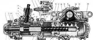
Hydraulic booster 5 (Fig. 60) is located under the hood in the front part of the tractor and consists of housing 3 (Fig. 61), bipod shaft 1, front 27 and rear 21 covers.
The switchgear includes a hydraulically controlled spool 26, springs 24, stops 25, front nuts 16 and rear 20.
Rice. 61. Power steering: 1 — bipod shaft; 2, 11 — ball bearings; 3, 23 — housings: 4 — adjusting screw; 5 — upper housing cover: 6, 7 — nut-cap; 8 — adjusting screw; 9— safety valve; 10 - plug; 11 - pin; 12 — spring: 13, 15 — nuts; 16 — front nut; 17 - seal; 18 - piston; 19 — spring washer; 20 — rear nut; 21 — rear cover; 22 — power steering screw; 24 — spool spring; 25 — emphasis; 26 — spool; 9.7—front cover.
The piston on one side is made of a rack and has three teeth of variable thickness, which engage with the teeth of the shaft sector 1, also of variable thickness. During assembly, the middle piston tooth is installed in the middle cavity of the sector. Adjust the gap in the engagement of the sector with the piston using adjusting screw 4.
During tractor operation, the oil flow supplied by hydraulic system pump 11 (Fig. 62) is divided into two branches to the separate hydraulic system and to the hydraulic booster. This flow division is accomplished by a flow valve.
The throttle opening of the flow valve spool is designed to bypass 10-12 l/min of oil required for the operation of the hydraulic booster. As the pressure in the hydraulic booster increases, the spool moves down and throttles the output from the valve to the mounted system. When a load is created in the mounted system, the spool moves up and throttles
outlet from the flow valve to the hydraulic booster. With simultaneous load on both branches, the spool occupies the same position as in the absence of loads, i.e. average.
When the steering wheel rotates, both nuts move relative to the piston in such a way that one of them approaches the end of the piston and throttles the drain hole, while the other moves away from the corresponding end, opening the drain hole. In this case, the flow, which was previously divided in half and passed through both cavities, will now go mainly through the cavity in which the drain hole is open, that is, it will be divided in proportion to the flow sections. The passage of different amounts of working fluid through the cavities is accompanied by a pressure difference, due to which the spool 26 moves towards low pressure and closes the hole.
In the cavity where the drain hole is closed with a nut, the pressure increases, moving the piston 18. The piston will move as long as the driver rotates the steering wheel. When the rotation of the steering wheel stops, the nut lags behind the piston and opens the drain hole, as a result of which the pressure in both cavities is equalized and the movement of the piston stops, and spool 26 is set to the neutral position.
When changing the direction of rotation of the steering wheel, the operation of the power steering is similar.
To limit compression and premature failure of the springs 24, stops 25 are installed in them.
During rotation, one of the nuts will deform the spring washer, and the force on the steering wheel will be greater, the greater the resistance on the guide wheels, i.e. spring washers are a simulator of the load on the guide wheels.
In case of pressure increase above 110 kgf1cmg
The oil squeezes out the ball of safety valve 7 and, bypassing the hydraulic booster, goes to drain into tank 9.
When disassembling the piston assembly, press in pin 11
(Fig. 61) in the rear nut, as shown in Fig. 63; unscrew nut 20 (Fig. 61) and remove it together with spring washer 19; push the hydraulic booster screw 22 towards the front cover 27 and remove the spool 26 with springs 24 and stops 25.
Reassemble in reverse order. The spring-loaded pin should be on the rear cover side. Before assembly, wash all parts in clean diesel fuel, and lubricate spool 26 with diesel oil. The lubricated spool should move without jamming under its own weight.
Screw 22 has a multi-start thread. Therefore, to correctly install the rear nut 20, select the appropriate approach in which the total gap between the nuts 16, 20 and the piston 18 is 1 ± 0.1 mm.
Rice. 62. Power steering diagram: I - nut; 2 — bipod shaft; 3 - piston; 4 - screw; 5 — power steering housing; 6 - spool; 7 - safety valve; 8 - filter; 9 — oil tank; 10 - flow valve; 11 — hydraulic system pump.
For this:
1. Install the screw assembly with the front nut and front cover into the piston so that the pin without a spring is in front or the thickening of the piston tooth in its operating position is directed downward. Turn the piston until the nut hole aligns with the pin. 2. Note the position of the pin in the piston and screw on the rear nut. In this case, if the hole for the pin of the nut screwed all the way has passed or has not reached the location of the pin by more than 90°, unscrew the nut and turn it to the side by the amount of the mismatch angle (i.e., place the nut on a different thread start).
3. Since the nuts are installed with some interference on the spring washers, tighten the rear nut 20, for which install a rod with a diameter of 7-8 mm to a depth of 15-20 mm in the end hole of the nut (Fig. 65) and a screwdriver inserted between the power steering screw and the rod , turn the nut until it is secured with a pin, which will click into the hole of the nut.
It is not recommended to insert the rod into the hole of the nut to a greater depth (than indicated), since it will interfere with the installation of the pin in its place. The pin will fully fit into its socket in the nut if the rod, inserted into the hole of the nut until it stops against the pin, is buried no more than 20 mm.
Maintenance of the hydraulic booster is maintenance of the hydraulic system: eliminating oil leaks through seals and connections, timely adding oil to the tank according to the marks on the oil gauge, washing filters. Frequency of filter washing and its sequence.
The power steering safety valve adjusted at the factory is sealed. The factory settings can be violated only in cases of violation of the adjustment parameters.
Before adjusting the safety valve, connect a pressure gauge to the discharge line (unscrew plug 10, Fig. 61), and install a stop between the bipod and the front beam on one side. Unscrew the cap and locknut of the safety valve. Start the engine and set the crankshaft speed to maximum. Then, turning the bipod towards the installed stop, use the steering wheel to adjust the oil bypass pressure through the safety valve (80-85 kgf/cm2 at a temperature of 15-35*C and 75-80 kgf/cm2 at a temperature of 35-80°C).
After completing the adjustment, without changing the position of the adjusting screw, tighten the locknut and cap. Replace the conical plug.
Steering maintenance consists of periodically checking the steering wheel play and tightening all threaded connections.
The steering wheel play should not exceed 25° with the engine running and the hydraulic pump turned on. If the play increases, tighten it
threaded connections of the propeller shaft, bipod, check the adjustment of the engagement of the bipod shaft sector with the piston teeth, and if necessary, replace worn parts.
In the hydraulic booster, the lateral clearance in the engagement of the teeth of the bipod shaft sector and the piston is adjusted. Check the gap and, if necessary, adjust it after two years of operation of the tractor in the following sequence:
1. Unscrew the cap nut 6 (Fig. 61), then, holding the adjusting screw 4 from turning, unscrew the lock nut.
2. Screw the adjusting screw 4 into the cap no more than 1-2 turns, then, holding screw 4, tighten the lock nut and screw on the cap.
In the steering, lubricate the bushings (Fig. 60) of the cardan crosspieces, as well as the lower spherical bearing through the filler hole, closed with plug 3.
The nylon bushings of steering shaft 10 operate without lubrication and are not lubricated during operation.
Lubricate the cardan crosspieces every 60 hours of tractor operation by pumping grease with a manual grease gun through a grease nipple (until grease appears from the gaps). Lubricate the lower bearing of the bipod shaft after 960 hours by filling it with a syringe to the lower edge of the filler hole, closed with plug 3.
content .. 71 72 78 ..
Assembly and disassembly of power steering T-40
When disassembling the piston assembly, it is necessary to recess the pin (11), which is located in the rear nut, unscrew the nut (20), then remove it together with the spring washer (19). Next, push the tractor power steering screw (22) towards the front cover and remove the spool (26) along with the stops and springs (24,25).
Assembly must be done in reverse order. Only the pin should be on the side of the back cover.
Remember! Before assembly, you need to wash all mechanisms in clean diesel fuel, and lubricate the spool with diesel oil.
In this case, it (the spool) should move without any jamming.
Correct installation
The screw (item 22) has a multi-start thread. Because of this, in order to carry out the assembly correctly, you need to select the recommended approach, and leave a total gap between the nut (16,20) and the piston (18) of 1 mm (permissible deviation no more than 0.1 mm).
1. Place the screw together with the front nut and cover in the piston, so that the pin is in front or the thickening of its tooth in the working position is directed downward. To do this, turn the piston until the hole of the nut and the pin match.
2. Next, mark the position of the pin in the piston and screw on the rear nut.
3. The nuts must be installed with some interference on the washers, tighten (20), and hold in the end hole of the rod with a diameter of 8 mm at a depth of about 17 mm along with a screwdriver. The pin should click into the hole. It is impossible to install the rod at a deeper depth, because it will prevent the pin from falling into place.
Gear tractor T 40: disassembly, assembly, do-it-yourself repair
The power steering of the T-40 tractor is designed to reduce the forces applied when rotating the steering wheel and transmitting one-way rotation from the steering wheel to the drive wheels.
Its serviceability is associated not only with maneuverability, but with safety - the wheels are less sensitive to road unevenness, and the trajectory is maintained even if the tires are seriously damaged.
Timely prevention of power steering T-40, disassembly, assembly, repairs, carried out efficiently, will help improve the controllability of the tractor and make working on it as easy as possible.
Design and principle of operation of the power steering of the T-40 tractor
Power steering is one of the elements of the T-40 steering structure. It is located under the hood, closer to the front. The main components that you will have to deal with during repair or maintenance are: covers (front and rear), stops, nuts, bipod, spool.
The power steering of the T-40 tractor operates on the principle of a piston. The oil is dosed by a spool located inside the piston.
Algorithm of operation of the T-40 power steering:
- hydraulic fluid is supplied from a gear pump;
- The spool valve distributes the flow to the rear linkage and tractor steering;
- pressure is supplied to the T-40 steering column.
When the steering wheel rotates, two nuts in relation to the piston move as follows: one moves towards the end, and the other moves away. Therefore, the oil flow always moves in one direction, tending to the open drain hole.
Do-it-yourself repair of power steering tractor T-40
The price for a T-40 power steering ranges from 10-13 thousand rubles; a comprehensive repair will cost about the same amount. Therefore, making repairs yourself and performing maintenance yourself is the best option for the tractor owner. Thanks to the video, you can learn in more detail about the repair of the T-40 steering column.
Disassembly and assembly
Disassembling the T-40 power steering is performed according to the following instructions:
- when disassembling the piston assembly, press the pin located in the rear nut all the way;
- the nut must be unscrewed and removed together with the spring washer;
- The screw is pushed towards the front cover, then the spool with springs and stops is removed.
Assembly is performed in reverse order, but the following tips should be followed:
- make sure that when assembling the pin is on the side of the back cover;
- the spool must move freely, without friction or jamming;
- before assembling the power steering, the component parts are washed with clean diesel fuel;
- The spool also needs to be washed and treated with diesel oil.
Do not allow clogs or foreign debris to get into the piston. This can lead to power steering failure or component wear.
How to properly install the power steering of the T-40 tractor
When installing and assembling the T-40 power steering, special attention should be paid to the position of the screw, since it is equipped with a multi-start thread. You will need to select the correct position for its entry, leaving a gap of 1 mm between the piston and the nut (preferably without deviations).
To ensure proper installation, it is recommended to follow the following instructions:
- together with the cover and the front nut, the screw is inserted into the piston so that in the operating position the thickening of the tooth faces the bottom and the pin is in front;
- the position of the pin is fixed and the back nut is screwed on. The nuts are fastened with slight tension so that the depth from the end hole of the rod does not exceed 17 cm. If you tighten it more, the pin may not fit into the right place. A click will indicate that the pin has entered correctly.