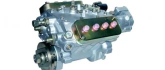
It’s worth starting with the fact that pumps from different manufacturers are installed on Kama cars with Euro 2, 3, 4 engine classes. Firstly, these are pumps of the YAZDA 337.20 series of domestic production, and secondly, specially produced injection pumps Bosch KamAZ Euro 2, Euro 3 and Euro 4. “Home” ones are cheaper, however, they are slightly inferior in the accuracy of fuel dosage. And yet, there are significantly fewer problems with them, at least those drivers who drive with just such a unit rarely switch to imported pumps, but the opposite happens quite often. Fuel injection pump YAZDA 337.20 - design and adjustment
Moreover, the transition from a Boshevsky to a Yaroslavl pump usually does not happen due to the poor quality of the injection pump itself.
The thing is that the KamAZ Euro fuel injection pump drive, manufactured by the Germans, does not withstand our operating conditions - torn out plates have become almost a mandatory attribute of an imported unit. There have been cases when the pump drive on the same car was changed 5 times within one year. The fuel injection pump system of the KAMAZ engine, depending on the engine model, has the following model:
- KAMAZ 740.10 engines - YAZDA 33-02 injection pump; — engines KAMAZ 740.10-20 — injection pump YAZDA 33-10; — engines KAMAZ 7403.10 — injection pump YAZDA 334; — engines KAMAZ 740.11-240 — injection pump YAZDA 337-40; — engines KAMAZ 740.13-260 — injection pump YAZDA 337-42; — engines KAMAZ 740.30-260 — injection pump YAZDA 337-20; — engines KAMAZ 740.31-240 — injection pump YAZDA 337-20.05; — engines KAMAZ 740.50-360 — injection pump YAZDA 337-20.04 or injection pump BOSCH PE8P120A920/5RV (0 402 698 817); — engines KAMAZ 740.51-320 — injection pump YAZDA 337-20.03 or injection pump BOSCH PE8P120A920/5RV (0 402 698 817); — engines KAMAZ 740.60-360 — fuel injection pump YAZDA 337-23; — engines KAMAZ 740.61-240 — injection pump YAZDA 337-23.01; — engines KAMAZ 740.63-360 — injection pump BOSCH PE8P120A920/5RV (0 402 698 818).
Repair of BOSCH fuel injection pumps with RQV…K regulators installed on KAMAZ vehicles
Introduction
This manual provides basic data for the repair and adjustment of high-pressure fuel pumps 0 402 648 611 installed on the internal combustion engines of KamAZ vehicles. RQ and RQV regulators will be considered in comparison with mechanical regulators RQV...K, installed on the internal combustion engines of KamAZ vehicles.
The video tutorial will later show a complete repair of an injection pump using the example of a P-type injection pump with an RQV regulator. K.
1. Repair of fuel injection pump with RQV…K regulators
1.1. General description of fuel injection pump assembly
Before assembling the fuel injection pump, it is necessary to wash and troubleshoot it. It is advisable to wash fuel pump parts and injector bodies in drum-type washers operating in a closed cycle. For the last 5 months, the author has been using a Geyser sink with a drum diameter of 700 mm.
When troubleshooting parts of the injection pump and regulator, the author recommends replacing the following spare parts when the plunger pairs are worn:
- 2 418 455 727 – Plunger pair – 8 pcs.;
- 2 418 459 037 – Discharge valve – 8 pcs.;
- 2 414 612 005 – Valve spring – 8 pcs.;
- 2 410 422 013 – Rotating sleeve of the plunger (if there is wear on the ball, look through an 8x magnifying glass);
- 2 417 010 022 – Complete fuel injection pump repair kit;
- 2 427 010 049 – Repair kit for fuel injection pump regulator;
- 2 421 015 057 – Regulator gasket;
- 2 447 010 043 – Repair kit for high pressure fuel pump valves.
When troubleshooting, pay attention to the working surfaces of the cam shaft, pushers, bearings and springs. The injection pump housing must be cleaned; before washing, all rings remaining after dismantling the plunger bushings must be removed.
Figure 1.1 shows the tools for installing the plunger and pusher and fixing the pusher.
Figure 1.1 – Tool kit for installing and fixing the plunger
The position of the pusher lock is such that the catalog number indicated on the pusher body is located on top, and the 0 mark on the rotating part of the lock is on the bottom. Install and dismantle the pusher stoppers on fully depressed cams in order to prevent breakage of the stoppers.
The cam shaft should be installed as shown in Figure 1.2.
Figure 1.2 – Position of the camshaft cams when installing and removing the pusher stops
Install the cam shaft as shown in Figure 1.3.
Figure 1.3 – Installation of the injection pump cam shaft
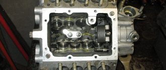
It should be noted that on the fuel injection pump shown in the photo, it is more convenient to dismantle and install the cam shaft from the regulator side. Many models use tapered bearings, so dismantling the cam shaft should be done through the front part of the injection pump after removing the front HF bearing cover.
Dismantling and installation of the cam shaft into the fuel injection pump housing is carried out using a press or with light blows through a copper or aluminum adapter.
It is recommended to carry out all impact work with rubber hammers.
Use metal plugs only once.
2. Adjusting the injection pump on the stand
The assembled fuel injection pump is installed on the stand. Initially, we adjust the feed angles of the injection pump sections in accordance with the test plan.
Figure 2.1 shows the connection of the test fluid supply to the injection pump on the stand. The supply connection point is indicated in the test plan for each injection pump. The connection point from the front of the injection pump is point 1, from the rear - 2. The supply connection in our case is carried out at point 3.2, in the return drain, respectively, to point 3.1.
Figure 2.1 – Connection points for supply of test fluid to the injection pump
Table 2.1 shows the lifting heights of the plunger on the injection pump of KamAZ vehicles of various models at which the fuel supply is cut off.
Table 2.1 – Height of lifting of the plunger on the injection pump of KamAZ vehicles
Plunger stroke, mm
When adjusting the angles, a plug is installed instead of the check valve and a pressure of 26 bar is maintained, the rack stroke and the lifting height of the plunger correspond to the data from Table 2.1. Next, the values for the start of supply by fuel injection pump sections are made in accordance with the test plan. In our case it is 1 – 7 – 5 – 2 – 4 – 3 – 8 – 6 in increments of 45 degrees.
To adjust the lifting of the fuel shut-off moment, use high-quality shims. In practice, there are washers from “left” manufacturers whose thickness differs from the one stamped on the washer by 0.05 mm or more.
The device for the rack exit can be made similar to that shown in Figure 2.2.
Figure 2.2 – Setting the rack stroke
Figure 2.3 shows devices for the rack stroke and plunger lift height. The values of all parameters should not exceed those specified in the test plan.
Figure 2.3 – Installation of devices for measuring rack stroke and plunger lift height
When setting the timing of the fuel shutoff, it should be taken into account that Bosch plunger pairs in most cases do not completely shut off the supply. Drops are allowed to fall at intervals of 1 drop per second (and possibly more often).
Next, according to the test plan, we install the fuel supply beacon. This operation must be carried out on all injection pumps. In our case, we set the stand dial to a position of 270 degrees from section 1, which corresponds to the beginning of the feed of section 8, and install the driving half-coupling of the load coupling, as indicated in Figure 2.4.
Figure 2.4 – Installation of fuel supply start beacon
After completing the repair, you should install the injection pump drive and, having installed the beacon as indicated in Figure 2.4, check the alignment of the marks on the injection pump housing and the drive coupling.
Before assembly, degrease the conical surfaces of the cam shaft and the driven coupling half, treat them with Loxeal 82-21 or similar and tighten to a torque of 75 Nm.
Vehicle power system design
As they say, power systems and electrical equipment are the most susceptible to malfunctions. Since you are faced with malfunctions of the KAMAZ injection pump , let's choose the most suitable KAMAZ injection pump model for your car. To do this, you should study the technical characteristics of the KAMAZ injection pump.
First of all, let's look at the injection pump 33-02, 334, 332-30, 337-80.01 of the KAMAZ-740 engine
Fuel injection pump KAMAZ 740 models 33-02, 3310, 334, 332-30, 337-80.01 are high-pressure fuel pumps with a V-shaped arrangement of sections and a distance between sections of 36 mm.
KAMAZ 740 fuel pumps models 33-02, 33-10, 334, 337-80.01 include a mechanical all-mode regulator and corrector.
The fuel injection pump KAMAZ 332-30, unlike previous models, has a mechanical dual-mode regulator with correctors (direct and reverse). KAMAZ engines, which are equipped with the following fuel injection pump models, comply with EURO-0 toxicity standards. If any problems occur with the engine or the engine runs unevenly, this is a sign of a malfunction of the KAMAZ injection pump.
Technical characteristics of fuel injection pump KAMAZ 740
| Injection pump model | Number of fuel injection pump sections | Diameter/maximum stroke of plunger (mm) | Nozzle model | Engine model | N nom. (hp) at n (min -1) | Where is the injection pump 332-30 |
| 33-02 | 8 | 9/10 | 33-02 | 740.10 | 210/2600 | KamAZ: 5320, 5410, 5511, 54112, 55102, 4310, 43101; URAL-4320, ZIL-133GYA |
| 33-10 | 8 | 9/10 | 271-01 271-02 | 740.10-20 | 220/2600 | KamAZ: 43101,4326, 54112, 55111, 5320, 5410, 53213,53202,431017, 551107, 55102, 551027, 541007, 551117, 431017; URAL 43207; ZIL-133GYA |
| 334 | 8 | 9/10 | 271-01 271-02 | 7403 | 260/2600 | KamAZ: 43114,4326-01, 43118-01, 53228-01, 55111-01, 43101-01, 53229-01, 53212-01, 54112-01, 53211-01, 53213-01; GAZ-5903 |
| 332-30 | 8 | 10/11 | 272-02 | 7408.10 | 195/2200 | LiAZ-5256 |
| 337-80.01 | 8 | 10/11 | 273-21 | 740.14-300 | 300/2600 | Specialist. cars |
Technical characteristics of fuel injection pump 337-20 engine
KAMAZ-740 EURO2 standard
The fuel injection pump KAMAZ 740 337-20 is a high-pressure fuel pump that has a V-shaped arrangement of sections with a distance between sections of 36 mm.
The KAMAZ 337-20 injection pump produces fuel injection pressures of up to 1200 Bar. kit 337-20 includes an all-mode mechanical regulator with reverse and direct corrector, as well as a boost corrector. Moreover, these engines comply with the EURO-2 standard. Production of engines with fuel injection pump 337-20 began in September 2002.
Technical characteristics of fuel injection pump 337-20 engine
KAMAZ 740 EURO 2
| Injection pump model | Number of fuel injection pump sections | Diameter/maximum stroke of plunger (mm) | Nozzle model | Engine model | N nom. (hp) at n (min -1) | Where is the injection pump 337-20 |
| 337-20 | 8 | 11/13 | 273-21 | 740.30-260E2 | 260/2200 | EURO-2 KamAZ-65115, 65116, 65117, 6540 |
| 337-20.03 | 8 | 11/13 | 273-20 | 740.51-320E2 | 320/2200 | EURO-2 KamAZ-6520, 6522 |
| 337-20.04 | 8 | 11/13 | 273-20 | 740.50-360E2 | 360/2200 | EURO-2 KamAZ- 6360-06, 6460-06, 5360-06, 5460-06 |
Technical characteristics of fuel injection pump 337-40, 337-70 engine
KAMAZ-740 EURO-1
The injection pump 337-40 KAMAZ 740 is a high-pressure fuel pump, which is equipped with sections with a V-shaped arrangement and has a distance between sections of 36 mm. The fuel injection pump 337-40 is equipped with a regulator with two modes, as well as a direct and reverse corrector. Produced since 1995.
| Injection pump model | Number of fuel injection pump sections | Diameter/maximum stroke of plunger (mm) | Nozzle model | Engine model | N nom. (hp) at n (min -1) | Where is the injection pump 337-40 |
| 337-40 | 8 | 11/13 | 273-30 273-31 | 740.11-240E1 7405.10 | 240/2200 240/2200 | EURO-1 KamAZ-55111-02, 65115, 53212-02, 54112-02, 54115, 53215, 53205-02, 53213, 53202, 53229-02, 54105-02, 53228-02, 4326, 4350 . |
| 337-40.01 | 8 | 11/13 | 273-31 | 740.22-240 | 240/2000 | Rules 96 Combine “Don-1500” |
| 337-40.02 | 8 | 11/13 | 273-31 | 740.02-180 | 180/2200 | Rules 96 Tractors T-150K, HTZ-170, IFA feed chopper |
| 337-70 | 8 | 11/13 | 273-31 | 740.11-240 | 240/2200 | Buses: NefAZ-5297, PAZ-5272, LiAZ-5256 |
Technical characteristics of fuel injection pump 337-42 engine
KAMAZ-740 EURO-1
The injection pump 337-42 is a high-pressure fuel pump, which is equipped with sections with a V-shaped arrangement and has a distance between sections of 36 mm. The injection pump 337-42 is equipped with a mechanical all-mode regulator, as well as a direct and reverse corrector. Produced since 2002.
| Injection pump model | Number of fuel injection pump sections | Diameter/max. plunger stroke (mm) | Nozzle model | Engine model | N nom. (hp) at n (min -1) | Where is fuel injection pump 337-42 |
| 337-42 | 8 | 11/13 | 273-20 | 740.13-260 | 260/2200 | EURO-1 KamAZ-43118, 44108, 65111, 6540 |
| 337-42.01 | 8 | 11/13 | 273-20 | 740.22-240 | 240/2000 | Rules 96 Combine “Don-1500” |
Fuel injection pump KamAZ Euro 2: Design and correct adjustment
The operation of diesel power plants is directly related to the supply of the fuel mixture to the combustion chamber; the KamAZ Euro 2 injection pump plays a major role in this action. A breakdown or failure of the fuel pump will immediately affect the operation of the engine, or even stop the unit altogether. Structurally, the pump is a reliable and durable mechanism, however, the fuel sold at gas stations often does not meet the required characteristics and subjects the product to increased loads.
Today KamAZ engines do not meet Euro-2 standards. Non-compliance with environmental standards was the reason for the cessation of production of units in 2006. However, the operation of engines is not prohibited; KamAZ vehicles with similar units are still in demand and travel across the vast expanses of the country. It is not surprising that installing fuel injection pumps on KamAZ Euro 2 is still of interest to users.
When is fuel volume adjustment necessary?
In general, the following signs indicate problems with the operation of the high-pressure pump and the need to reduce or add fuel:
- Changes in engine power and its operation intermittently. Usually the reason here lies usually with the injection of fuel portions of different volumes, which requires adjustment of the fuel injection pump or, in advanced cases, repair of the latter.
- Reduced engine power. The reason lies in the untimely entry of fuel into the combustion chamber, which leads to delayed ignition, incomplete combustion, and this negatively affects efficiency. The solution will be to adjust the injection pump, namely how to add or reduce fuel. In advanced cases, repairs and replacement of main components may be necessary.
- Fuel leaks or increased consumption. The problem is usually associated with wear of individual components of the fuel injection pump or engine due to low-quality fuel. Problems can be minimized at the initial stage, but in the future repairs or even replacement of the injection pump and its key components will be required.
- Extraneous noise when starting the engine and its subsequent operation. Here the reason may be either incorrect adjustment of the fuel injection pump, or its wear, engine malfunctions, or fuel system.
Correct operation of your KAMAZ truck plays an important role in the service life of the pump. To prevent problems and reduce unnecessary transport downtime, follow the following rules:
- for refueling, use only high-quality fuel from proven gas stations;
- Replace fuel filters regularly;
- carry out preventive monitoring after 4000-6000 hours of operation;
- periodically drain the water from the fuel filter sump;
- If there are problems in operation, carry out diagnostics and repairs in a timely manner.
At the same time, you should not count on the magical properties of numerous additives, which, if the quality is insufficient, can lead to the opposite effect, “masking” the problems.
Types, purpose and principle of operation of injection pump
As already mentioned, without a fuel pump, the operation of a diesel power plant is not possible. In engines of this type, the unit is entrusted with the task of dosing diesel fuel and supplying it to the combustion chamber at the right time. In addition, the pressure with which the portion is delivered is also important. The requirements complicate the work algorithm and force us to operate under increased load conditions.
Fuel injection pump YAZDA 337.20 for KamAZ:
KamAZ power plants, with an environmental class corresponding to Euro 2, use high-pressure pumps of several brands. Among manufacturers, the “lion’s” share falls on fuel injection pumps of the YAZDA series, used on KamAZ Euro 2. Products of the modification “337.20” are produced by a machine-building enterprise located in the city of Yaroslavl. The product is popular and accessible primarily due to its pricing policy. In addition, reliability and simplicity make the pumps less demanding, and balances the disadvantage associated with the accuracy of fuel dosage. Second place goes to the imported Bosch injection pump, installed on KamAZ of Euro 2 standard. The product is distinguished by its quality and accuracy, but there are often complaints about the pump drive, which does not withstand operating conditions.
The operating principle of the pump is the same, the brand does not matter. Diesel from the fuel container passes through filter elements that clean the liquid. The pistons of the low pressure pump create pressure and supply diesel fuel to the injection pump. The parts regulate the necessary operating order, distributing diesel fuel through the pipes and directing it to the sprayers. The latter are responsible for dispersion, which affects the correct combustion. Some of the unused diesel fuel goes back into the fuel tank, while some remains in the pipes. You can also read about KamAZ 7850.
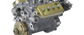
Bosch injection pump for KamAZ:
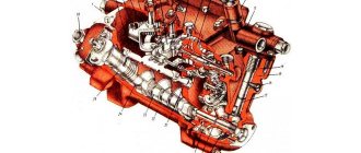
skeleton
The frame of the Bosch pump contains the parts necessary for the functioning of the mechanism: pump sections, a shaft with cams, and a rotation impulse regulator. The material of manufacture is aluminum alloy, from which the intake and shut-off channels are cast, as well as voids for mounting the pump sections, bearing shaft, regulator drive gears, fuel inlet and outlet fittings. The flank end contains a regulator plug with a reduced pressure pump. The plug has a fitting through which the injection pump is lubricated under pressure.
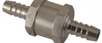
A cover is placed on top of the empty frame, to which mechanisms are attached that control the number of revolutions of the regulator and the fuel section plate. A pipe with a valve in the form of a ball is installed in the front part of the frame. The product maintains diesel fuel pressure within 0.06 to 0.08 MPa. The bottom of the frame contains a void into which a shaft with cams is installed.
KamAZ high pressure fuel pump:
Shaft with cams
The shaft with cams transmits displacement to the plungers of the pump sections, diesel fuel is supplied to the chambers at the right time. The shaft is made of steel, the loaded surfaces are calcined with cement powder to 0.7-1.2 mm, rotation occurs through two bearings. The shaft is protected from leaks by a cuff, the material of the product is rubber. The front end of the shaft drives a clutch that sets the diesel injection angle. Rotating, the shaft transmits pressure to the pushers and then to the pump plungers through the heels. By changing the thickness of the heels, we influence the nature of the fuel supply; an increase in thickness provokes an early supply and vice versa.
Pump departments
The pump section dispenses and supplies diesel fuel to the nozzles. Each unit includes a frame, a plunger pair, a rotation sleeve, elastic elements of the plunger, a discharge valve and a pusher.
The frame is equipped with a flange that secures the section to the pump using studs. The pin holes are oval in shape; it is possible to adjust the uniformity of diesel supply to each compartment individually (turning clockwise reduces the supply, and vice versa). The plunger pair is directly involved in cutting off and transporting diesel fuel and consists of a sleeve and a plunger. The parts are precision made, the material is steel with the addition of chromium and molybdenum, followed by hardening and cooling with nitrogen. The plunger acts as a piston, has axial drilling and radial grooves that change the flow of diesel fuel. The precision pair of discharge valve and seat are made of steel, after the elements are hardened and cooled. Replacement of components is possible only as an assembly.
KamAZ injection pump cam shaft:
High pressure fuel pump
The high-pressure fuel pump (HFP) is used to accurately dose fuel and supply it at a certain moment under high pressure to the injectors. Auto mechanics and drivers often refer to the high-pressure fuel pump as fuel equipment. Currently, mechanically driven multi-plunger injection pumps are gradually giving way in diesel power systems to more advanced designs, such as computer-controlled pump-injector systems and rotary-type distribution pumps used in Common Rail power systems. Nevertheless, pumps of classical design are still widely used on many automotive engines.
Injection pump classification
High pressure fuel pumps are classified according to the following criteria:
- multi-plunger (there is one plunger for each cylinder);
- distribution (one plunger supplies fuel to several cylinders);
Multi-plunger injection pumps can be made with an in-line or V-shaped housing.
- mechanical;
- hydraulic;
- pneumatic;
according to the fuel dosing method:
- with regulation of the amount of fuel supplied per cycle (cut-off);
- with regulation of cyclic supply by throttling at the inlet (changing the filling of the above-plunger volume with fuel using a throttling device in the channel supplying fuel to the inlet window; used in distribution pumps).
Distribution injection pumps are divided into plunger and rotary.
Multi-plunger injection pumps with mechanical drive
In automobile diesel engines, multi-plunger pumps with a mechanical drive and regulation of the amount of fuel supplied by a cutoff have become widespread. Let us consider the design of such a pump using the example of a high-pressure fuel pump of the YaMZ-236 engine, which belongs to in-line plunger-type pumps and provides an injection pressure of 16 MPa (Fig. 1).
In the lower part of the pump housing 1, a cam shaft 12 with a gear 11 is mounted on two ball bearings. The cam shaft has profiled cams 19 according to the number of engine cylinders and an eccentric for driving the fuel pump, which is attached to the mating plane of the injection pump.
Roller pushers 18 are installed in the housing partition opposite each cam. The axes of the rollers 15 with their ends fit into the grooves of the pump housing, preventing rotation of the pushers. Adjusting bolts 40 are screwed into the center of the pushers, on which the plungers of the pump sections rest. All sections are arranged in the same way, they are interchangeable, and their number is equal to the number of engine cylinders.
The pump section consists of a sleeve 35 with a plunger 6, a discharge valve 33 with a seat 34, a spring 32 and a stop 31, a fitting 7, a rotary sleeve 16 with a gear 4, a pusher 18 with an axis and a roller 15, a plunger spring 38 and support plates 28 and 39.
The plunger sleeve is fixed in the body with a locking screw. The plunger and its bushing form a so-called plunger pair. The plunger pair is made of chrome-molybdenum steel and hardened to high hardness. After finishing the selection process, the plungers and sleeves are assembled so as to ensure a gap of 5...2 microns in their mating. The discharge valve 33 and its seat 34 are manufactured with the same precision. Therefore, these parts are called precision, and they are not interchangeable.
The discharge valve seat is pressed to the plunger bushing by a threaded fitting 7 through a sealing copper gasket. A high-pressure tube is attached to the fitting, connecting the pump section to the nozzle. Cam 19, pusher 18 and spring 38 provide reciprocating movement of plunger 6.
The plunger sleeve 35 is fixed in the body with a locking screw 29. The rotary sleeve 16 is loosely placed on the sleeve, and the protrusions 17 of the plunger fit into the vertical grooves of the lower part of the sleeve. At the upper end of the rotary sleeve there is a gear ring 4, which engages with a gear rack (common to all sections), which can move along the injection pump body.
Speed control device
The KamAZ Euro 2 fuel injection pump design provides for the use of a speed control mechanism. The fact is that for stable operation of the power plant, a steady state is required. The parameter provides for constant rotation of the shaft, heating of the lubricant, etc. To achieve the indicators, the values of the torsion impulses and counter-motion impulses are equalized. Operation upsets the balance, since the applied force in the modes differs, as a result, the parameter values deviate from the required ones. The return of impaired indicators is possible thanks to adjustment. The process takes place manually (fuel pump rail), or using an automatic machine that regulates the frequency. The last element maintains the user-suggested shaft speed by changing the portion of diesel fuel taking into account the load in automatic mode.
KamAZ engines are equipped with a direct type control device, installed in the frame of the pump with adjustment on the plug.
- A device that sets the required value of the controlled variable;
- Device for perceiving an influencing quantity;
- Comparison device;
- Execution device;
- A device that actuates the regulator.
KamAZ frequency regulator:
Clutch that changes the supply of diesel fuel
The Bosch KamAZ Euro 2 fuel injection pump design and others provide for the introduction of diesel fuel 18° before the piston reaches the top point on the compression stroke. This is done to mix the air and the diesel charge in order to get maximum power.
Increasing the speed of revolutions reduces the time for combustion preparation. To prevent the procedure from starting after the top point and reducing useful work, diesel fuel is administered ahead of schedule, with an increase in angle. This is done with a clutch that changes the supply of diesel fuel by turning the shaft with cams in the direction of circulation in relation to the drive. The clutch improves engine starting and saves diesel fuel.
On KamAZ, the automatic installation uses an adjustment range from 18° to 28°. The product is located at the conical end of the injection pump shaft, fastening is provided by a nut and washer.
The Bosch injection pump coupling consists of:
- skeleton;
- Main half coupling;
- The secondary half of the coupling;
- Gaskets;
- Glass stops of elastic elements;
- Thrust washers;
- Regulating gaskets.
How the injection pump system works
The Kama Automobile Plant produces its trucks equipped with a diesel engine. They comply with the Euro-2 environmental standard. The production of such power units has been prohibited in Russia since 2006, but they can still be used if they were produced earlier.
Over a long period of operation, they showed their best side and became famous for their reliability and durability. Much of the credit for this goes to the high-quality assembly of this unit.
The KAMAZ Euro 2 injection pump device includes the following main components:
- aluminium case;
- bypass valve;
- clutch that controls fuel injection advance;
- roller bearing;
- camshaft;
- plunger;
- inlet;
- discharge valve;
KamAZ is equipped with Euro-2 fuel injection pumps from two manufacturers - domestic and foreign (Bosch). In practice, the first option turned out to be more acceptable, since it is not afraid of harsh climatic conditions and is cheaper, unlike the German one.
Malfunctions and repairs
You can repair KamAZ fuel injection pump yourself if you have the necessary tools and equipment.
Main fuel injection pump malfunctions and reasons for their occurrence:
- Water in the fuel mechanism. This breakdown may indicate a malfunction of the fuel filter element, diluted fuel, or a leak in the fuel drives.
- Reduced and uneven supply of working fluid. In this case, it is recommended to check the plunger for damage, and also inspect the discharge valves and rack clamps. The capacity of the injectors should be checked.
- The diesel fuel is running out. The cause of this breakdown may be a leak in the fuel drive. The damaged element should be replaced.
- The drive is tearing. It is recommended to inspect the crankshaft, as well as the main components of the power unit for damage and foreign bodies.
- Delay of the working fluid injection system. Such a malfunction can be caused by damage to the plane of the adjusting bolt of the pusher element, the roller axis and failures in the rotation speed of the cam shaft.
How to remove and disassemble
- Remove the terminal from the battery.
- Remove the radiator.
- Remove the vacuum pump.
- Remove the oil dipstick guide pipe.
- Remove the oil filter filter mechanism.
- Turn the crankshaft in the direction of rotation until it stops.
- Disconnect fuel drives.
- Remove the vacuum hose.
- Block the crankshaft from turning.
- Unscrew the bolt in the center of the coupling.
- Remove the chain tensioner.
- Pull out the pump by dismantling the fuel pedal drive.
Disassembling the KamAZ fuel injection pump is done as follows:
- It is necessary to remove the metering type valve from the end of the pump housing. To do this, you need to unscrew the bolts of the pressure plate and release the advance valves of the injection system.
- Then you should remove the fastenings on the top cover.
- You need to disassemble the control board to gain access to the electronics.
- It is necessary to set the required position of the crankshaft.
- Then you need to dismantle the bearing using special equipment.
- At the end, all parts should be washed and their surface polished.
Adjusting the pneumatic corrector
The function of the KamAZ 740 injection pump pneumatic corrector is to regulate the fuel supply. When the air flow pressure decreases, the amount of fuel supplied is reduced, which prevents overheating and smoking of the engine. Also, the operation of such equipment affects engine oil consumption: if everything is in order, then oil consumption is uniform.
Adjusting the pneumatic corrector allows you to change the amount of fuel entering the injectors. The whole process is very simple, does not have a complex sequence of actions and can be easily done with your own hands. The pneumatic corrector is adjusted by two bolts:
The first is responsible for spring tension and is located coaxially with the spool. The corrector operates at increased pressure, which means it is necessary to increase the spring tension by tightening the bolt.
The second screw is responsible for the direct supply of fuel; unwinding it will increase the volume of incoming fuel.
On the Internet you can find pictures and videos showing step-by-step adjustment of the corrector. Fuel supply corrector circuit:
How to add or reduce fuel
Adjusting the Bosch injection pump on KamAZ makes it possible to add fuel, i.e. set the required fuel supply value.
Procedure for reducing fuel:
- Using a key of 13, you need to adjust the air flow to the mechanisms of the power unit. Thanks to this, diesel will be able to mix with air.
- Make adjustments to the corrector and start the motor for testing.
- If necessary, you need to further tighten the air flow until the smoke stops coming out.
In order to add fuel to the KamAZ injection pump (Euro-2 or Euro-3), you need to do the following:
- Tighten the special screws that are located in the upper and side parts of the working fluid supply.
- When unscrewing the bolts, you need to increase the gap for the passage of the combustible mixture. This will help normalize the performance of the power unit and the lubrication system of the high-pressure fuel pump.
- Having increased the diameter of the hole, you should start the engine and check the operation of all systems.
How to install correctly
Installation (installation) of the fuel pump must be carried out using special equipment.
In order to correctly supply and install a high-pressure fuel pump on a KamAZ truck, do the following:
- The vehicle is installed on a special platform.
- Mount the driven clutch onto the advance clutch and secure everything with bolts.
- Turn the coupling so that the bosses of the driven type coupling half are in a horizontal position, and the mark on the end part is in the pointer area.
- Install the flange assembly with the drive coupling half and plate packs. The flange should be located on the left side of the housing.
- Install the fuel pump along with the coupling onto the engine and secure everything with mounting bolts.
- Before tightening the bolts, adjust the flatness of the plate packs by moving the flange along the drive shaft.
- The pump is mounted on a block of cylindrical elements in a vertical position, preventing it from blocking.
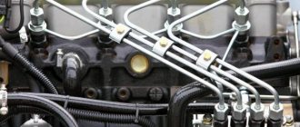
- The injection pump sections are connected to the injectors.
- Adjust the advance angle of the injection system.
- Check the presence of oil fluid in the injection pump housing.
- Connect the oil inlet and outlet pipes.
Principle of operation
The fuel mixture comes from the fuel tank and passes through a fine filter. The booster pump provides pressure that supplies fuel to the fuel injection pump itself.
The piston group provides a stroke to distribute the liquid through the tubes, directing them to the nozzles, which spray fuel into the combustion chamber.
Its remains and accumulated air flow back into the fuel tank. That part of the fuel that has passed the section between the needle and the sprayer remains in the drain pipes.
The KamAZ Euro 2 injection pump has a low pressure pump on the regulator cover. It is made in the form of a piston system, the movement of which is started by the cam shaft. Due to the change in crankshaft frequency, the design has an addition in the form of an automatic clutch, which is necessary to advance fuel injection.
Ignition system
There are a number of requirements for the launch system itself that are necessary for the normal operation of the car. These include:
- creating a spark in the cylinder at a certain moment;
- ensuring a rational engine starting moment, that is, the spark should appear with optimal advance, the interval of which varies depending on the engine speed and the current load;
- a certain strength and energy of the spark, the quantitative value of the energy varies proportionally depending on the physical and chemical characteristics of the fuel mass.
Ignition can be carried out in the following ways:
- through the microprocessor of an electronic device, where electrical energy is stored. The microprocessor controls the resulting energy and creates a spark;
- contact method, where the process is controlled by a special distributor - distributor;
- in a contactless way, where what is happening is controlled by a transistor switch that interacts with contactless sensors.
The processes are different, but the design itself has many similar parts. For example, spark plugs, a battery, a switch, devices for distributing and accumulating charges, as well as a 1703 KAMAZ belt.
Read more: Mercedes-AMG A45 2022 photo price and characteristics of a powerful hatchback from Mercedes 2nd generation
Source
The procedure for adjusting the injection pump
The adjustment process is accompanied by the following actions:
- washing the structure with special compounds;
- checking the low pressure valve. It should be unscrewed when closed, the upper section is upholstered for settling. As a result, the bypass hole should close;
- assessment of the correct operation of injection advance;
- adjust the cyclic feed by unscrewing or tightening;
- idle adjustment - normally it gives 770 rpm;
- checking the hydraulic corrector is done by turning it in any direction.
The installation of fuel injection pumps should be entrusted to specialists - this requires experience and the availability of equipment. Otherwise, there is a risk of unpleasant consequences - from a fuel leak to a major engine overhaul.
Video on the topic: KAMAZ Euro 2 injection pump
Basic principles of installing fuel injection pump on KamAZ and setting injection timing
The need to regulate the injection timing arises among drivers of Euro 2 and Euro 3 KamAZ vehicles.
There are situations when the plates break while traveling outside the city. But how to be and what to do, we will consider the details further.
The moment of injection is the meaning of the process
The injection moment is the beginning of the fuel supply at the moment when the valve is at its maximum highest point with the intake and exhaust pistons closed. As a result, the piston compressed the air as much as possible, which means fuel can be supplied.
Adjustment of this process is necessary for the following reasons.
- This period is different for each power unit.
- Differences in fuel, for example, winter and summer diesel fuel.
For ease of adjustment, each engine has corresponding marks and degrees. If you set the injection timing strictly according to the specified values, then KamAZ will behave properly, provided that it has a calibrated engine, a high-pressure fuel pump and GOST fuel.
How to install a fuel injection pump on a KamAZ? The drive is installed on a key on the gearbox side. The coupling can be rotated in two directions by 180 degrees. If the drive clamp screw is located in the upper part, then the mark on the pump and coupling should be opposite each other.
Having installed everything as expected, you can start the engine. If it happens that the engine activation is not completed, and thick white smoke is pouring out of the exhaust pipe, then this means that they have been mixed up by 180 degrees. The problem can be solved by turning the coupling in the other direction.
Reference! If it turns out that there are several marks on the coupling, then it is recommended to place it approximately in the middle of the adjustment slots.
Settings
Injection timing and ignition are different names for the same process.
Injection is the start of the supply of fuel mass when the piston moves to the maximum point. The KAMAZ EURO 2 starter must be in good working order. The intake valves must be closed, as well as the check valves. Due to this, maximum pressure appears in the functioning chamber. At the same time, fuel is supplied. Of course, diesel cars are tuned during factory maintenance. However, such debugging is not enough. Due to operating conditions and varying quality of automotive fluids, the adjustment must be repeated periodically.
Each power plant has special marks (or degrees), which are marked for the convenience of self-calibration. If the device is debugged and the settings are set according to the marks, the motor will function in its optimal mode. The KAMAZ EURO 2 engine, fuel, lubricants and spare parts used in the process must comply with all GOST requirements.
After the procedure, during which the car owner has set all elements of the system to the factory marks, he must firmly tighten the special clamps on the engine and turn it on. The vehicle should not have any problems starting and should start the first time. If this does not happen, or white smoke begins to come out of the exhaust part, then this indicates an error - the injection pump has been positioned 180 degrees. The error is corrected in the reverse way: the parts are unscrewed, the elements are rotated, and the engine is restarted.
If there are no factory marks, the elements must be installed in the middle position of the adjustment marks
To ensure correct installation, special attention must be paid to the injection time.
Signs of injection
There are two points of incorrectly adjusted injection:
Since there can be two incorrect settings, each of them has its own symptoms. It is important to correctly distinguish between the symptoms indicating these failures.
Late injection
This is a situation in which the check valve of the KamAZ 740 fuel injection pump is already lowering from the maximum upper point, and the fuel is just starting to flow, and an explosion follows.
In the functioning of the power unit, this is shown by several signs.
- White exhaust gases, especially when the engine is cold.
- The number of revolutions increases.
- It works smoothly.
- Quiet pressing of the gas pedal is accompanied by shaking of the engine at medium speeds. Afterwards it seems to break through, and the shaking disappears at elevated levels.
- KamAZ doesn't pull well.
- Increased fuel consumption.
- Overheat.
Early injection
A situation in which the piston has not reached its maximum point, but the combustible mixture is already entering, the explosion is directed towards the piston. The following signs indicate a problem:
- hard operation of the motor;
- with a sudden change of gas and increased load, a ringing is noted, and with increasing temperature the sound intensifies;
- if the injection occurs too early, white smoke is observed from the exhaust pipe;
- weak traction;
- increased fuel consumption.
Reference! The torque set at the factory is usually a little late.
Basic rules for installing injection
There are several rules for setting injection timing that should be followed.
- It is preferable to start manipulations at the operating temperature of the motor. However, if the symptoms are obvious, then you can start working in cold weather.
- We install the drive so that the mark is on top, then lower the two bolts by 17 degrees.
- If the injection is early, then move the pump drive in the direction of travel or clockwise.
- If the injection is late, then vice versa.
- You need to move the drive a little at a time and constantly tighten the bolts.
After all the manipulations, we start the KamAZ engine, such as art. 337 1111005 20. It is important that when it is activated during a sharp throttle, a ringing sound is heard. In this case, we move the drive back a little. The ringing will disappear, and the moment will be established.
Setting the injection timing
To perform the procedure, you need to prepare a metal rod with a diameter of 10 mm, a length of 30-40 cm and a 17 mm wrench.
Reference! The components of a diesel engine fuel equipment are high-precision instruments, and when installing a V-type injection pump on an engine, it requires perfect determination of the angle of injection of a diesel fuel injector into the working cylinder on the compression stroke. An error of one degree can cause the power unit to fail and lead to its overhaul.
The procedure for installing the KamAZ 5320 fuel injection pump with simultaneous setting of the injection timing angle is based on the following:
- raise and secure the cabin;
- on the left side of the motor, on the top, in the rear, on the flywheel housing housing there is a mechanical device, the rod of which must be lifted and rotated 90 degrees, then lowered into the slot on the housing;
- From the bottom of the KamAZ, use a 17 mm wrench to remove 2 bolts and remove the mudguard;
- insert a metal rod through the slot in the casing into the hole in the flywheel and turn the engine crankshaft from left to right until the locking rod on top blocks its further movement;
- check the position of the fuel pump drive shaft located in the camber of the engine cylinder block (top);
- in the case when the KamAZ 55111 fuel injection pump drive coupling is turned with the installation scale up, then align the zero mark of the drive with the mark on the fuel pump flange and tighten the two mounting bolts;
- otherwise, the stopper is raised and the engine crankshaft is rotated one revolution, and then the above steps are performed again.
After tightening the drive coupling bolts on the fuel injection pump flange, the flywheel stopper rises, rotates 90 degrees and lowers into the groove. A dirt shield is installed on the bottom of the flywheel housing. After which the truck cab is lowered and the clamps are raised to the upper position.
At this stage, all manipulations in order to install the injection pump are completed.
Kamaz ignition installation
The Kamaz ignition installation is determined by this advance angle, it is impossible to say definitely. This is indicated by factors of proper engine operation.
Fuel quality, piston group wear, and fuel injection pump adjustment on the bench. The ignition timing angle is selected experimentally and experimentally. According to one mechanic I know, the engine says the letter R when you press the gas pedal sharply.
Ignition should be early within 10-15 degrees.
Why do they ignite earlier?
Pre-ignition is done to ensure that the fuel ignites before the piston reaches top dead center. When the piston reaches TDC, the pressure of the burning fuel increases to a maximum. Under this condition, correct engine operation is achieved. The pump position is set so that the piston has not yet reached TDC and the fuel pump has already injected fuel into the cylinder.
Two plates are visible in the photograph. On the right there is a mark on the left scale with the ignition timing. Based on them, we determine how much to advance.
The mark on the right plate is as shown in the photograph. The piston of the first cylinder approaches top dead center. The scale on the left plate shows the position of the fuel injection pump at the time of fuel injection.
How to set the ignition
First of all, we set the piston of the first cylinder to top dead center, at the moment of fuel compression. We must understand how to do this. After all, the piston comes to TDC twice in one cycle of engine operation. It’s easier to determine by the pump. There are marks on it, the combination of which determines the desired phase.
If the pump has been removed. It’s more complicated here; you need to remove the valve cover of the first cylinder and rotate the engine clockwise. Until the stopper is activated, indicating the position of the piston of the first cylinder at TDC.
Now we need to navigate by the valves; if, when approaching TDC, the rocker arms are not movable and the valves close, then this is our position. Otherwise, before TDC one valve will close immediately after TDC the other valve opens. This is not the correct piston position for adjustment.
If the stopper is in the piston position at TDC at the moment of compression of the first cylinder, then the mark on the right plate indicates this.
Now you need to loosen the upper and lower mounting bolts. Accordingly, the injection pump will be released. And you can already change the ignition timing
Please note the center scale mark is located forward of the right plate mark. This indicates that fuel was injected first, and then the piston reached top dead center.
The ignition is set within 3.5-7.5 divisions on the scale.
That is, the greater the advance angle, the more it is necessary to move the mark along the scale. The Kamaz ignition setting is determined by the advance angle, it is within 10-15 degrees.
Source