We will learn how to adjust the injection pump of the D-245 diesel engine and its structure in this article.
High-pressure fuel pumps for D-245 engines
A high-pressure fuel pump is a mechanism that ensures the flow of diesel fuel into the combustion chambers of the cylinders. The fuel pump is one of the main structural parts of the diesel injection system.
In this case, fuel is supplied in certain doses and at specified intervals. These are two tasks that an injection pump should ideally perform - pumping a precisely adjusted amount of diesel fuel under pressure and determining the designated injection moment.
The main component of the pump is a plunger pair; it combines a plunger (piston) and a sleeve (cylinder). These elements are produced in factories with particular precision and using the highest quality steel. A very small gap is maintained between them (precision mating). Injection pumps differ in their design:
- in-line pumps - in such variations, diesel is pumped into each cylinder using a separate pair of piston and cylinder; - distribution pumps - they are usually equipped with one or a pair of plungers that operate on all cylinders; - main pumps - pump fuel exclusively into the batteries.
Injection pump for power units D-245.
Diesel engines of the D-245 model, which are installed on many trucks of the ZIL, MAZ, GAZ and others series, are equipped with a high-pressure fuel pump marked 773.
Design.
The entire mechanism has a block design. TNVD-773 consists of 4 sections located in one housing. Such a device involves cyclic injection of diesel, using dosing using a spool. Fuel pumps of this type are combined with a special regulator and a fuel pump into one common unit.
Lubrication principle.
The working parts of the injection pump are lubricated by supplying oil from the main lubrication system. After stopping operation, the oil is drained into the crankcase. After each new installation of a fuel pump on the engine, it is recommended to fill it with oil in an amount of about 250 ml. The injection pump is filled with oil through the oil drain neck. When installing a high-pressure fuel pump, the welding plate intended for it must have a clean surface without damage or chips.
Purpose and design of the fuel pump
The high pressure fuel pump (HFP) is designed to inject fuel into the cylinder.
The device performs two main functions:
- Adjusting the fuel content in the cylinder.
- Fuel supply at regular intervals.
There are two main nodes to perform the functions:
There is one plunger-bushing pair per cylinder. The material for the manufacture of elements is high-strength alloy steel. To reduce friction forces, the surface of the products is carefully ground.
Sprayers
The atomizer is designed to atomize the injected fuel in the combustion chamber of the engine so that it mixes perfectly with the air. Combustion is then carried out economically, that is, the largest part of the thermal energy of the fuel is converted into engine work. Nozzles are manufactured in different sizes with different numbers of injection holes, different diameters and different spray angles.
Nozzles are subjected not only to mechanical, but also to thermal stress, since they work directly in the combustion chamber of the engine. Imperfect fuel atomization can cause other than a decrease in engine power (for example, piston burnout, etc.). This is why sprayers should be given maximum attention.
Prices for repair of injection pump MOTORPAL
| Repair of injection pump MKSM 800 | |
| Name | Price with VAT |
| Diagnostics of injection pump PP3M85K1e-3095 (stand) | 1500 |
| Adjusting fuel injection pump PP3M85K1e-3095 (stand) | 3500 |
| Overhaul of fuel injection pump PP3M85K1e-3095 | 7500 |
| Plunger pair EM85K1e-14 60403-14 | 2700 |
| Seal of plunger pair 31093186 | 40 |
| Discharge valve 60042-56 | 800 |
| Discharge valve seal 34098735 | 20 |
| Feed pump CD1M-2291 9902291 | 4500 |
| Cam shaft PP3M 20019-68 (as needed) | 9500 |
| Fuel filter FJ2R1252 9901252 | 800 |
| Pumping section CV60503-07 60503-07 | 4000 |
| Repair of injection pump UNC 060 (UNC 060) | |
| Name | Price with VAT |
| Diagnostics of injection pump PP3M85K1e-3143 (stand) | 1500 |
| Adjustment of fuel injection pump PP3M85K1e-3143 (stand) | 3500 |
| Overhaul of injection pump PP3M85K1e-3143 | 7500 |
| Plunger pair EM8K 60403-16 | 2700 |
| Seal of plunger pair 31093186 | 40 |
| Discharge valve 60042-56 | 800 |
| Discharge valve seal 34098735 | 20 |
| Feed pump CD1M-2278 | 4500 |
| Cam shaft PP3M 20019-68 (as needed) | 9000 |
| Fuel filter FJ2R1252 9901252 | 800 |
| Repair of injection pump UN 053 (UN 053) | |
| Name | Price with VAT |
| Diagnostics of injection pump PP4M85K1e-3096 (stand) | 1500 |
| Adjusting fuel injection pump PP3M85K1e-3096 (stand) | 3500 |
| Overhaul of injection pump PP3M85K1e-3096 | 8500 |
| Plunger pair EM85K1e-14 60403-14 | 2700 |
| Seal of plunger pair 31093186 | 40 |
| Discharge valve 60042-56 | 800 |
| Discharge valve seal 34098735 | 20 |
| Booster pump CD1M-2291 9902291 | 4500 |
| Fuel filter FJ2R1252 9901252 | 800 |
| Pumping section CV60503-07 60503-07 | 4000 |
| Cam shaft PP4M 20019-54 (as needed) | 9500 |
| Repair of injection pump LKT 81 (LKT 81) | |
| Name | Price with VAT |
| Diagnostics of injection pump PP4M9K1e-3138 (stand) | 1500 |
| Adjusting fuel injection pump PP4M9K1e-3138 (stand) | 3500 |
| Overhaul of injection pump PP4M9K1e-3138 | 8500 |
| Plunger pair EM9K 60403-09 | 2700 |
| Seal of plunger pair 31093186 | 40 |
| Discharge valve 60042-55 | 800 |
| Discharge valve seal 34098735 | 20 |
| Booster pump CD1M-2292 9902292 | 4500 |
| Cam shaft PP4M 20019-54 (as needed) | 9500 |
| Repair of injectors MKSM 800, UNC 060, UN 053 | |
| Name | Price with VAT |
| Diagnostics of injector VA78S453 a 2685 | 200 |
| Nozzle adjustment (stand) | 250 |
| Nozzle overhaul | 450 |
| Sprayer DOP160S 430-1436 | 900 |
| Repair of injectors LKT 80, LKT 81 | |
| Name | Price with VAT |
| Diagnostics of injector VA78S453 a 2682 | 200 |
| Nozzle adjustment (stand) | 250 |
| Nozzle overhaul | 450 |
| Sprayer DOP 150 S 535-1417 | 950 |
Types of fuel pumps
There are three main types of fuel pumps:
In in-line installations, fuel is supplied to each cylinder by a separate plunger-bushing pair.
In distribution devices, the mixture is supplied by one or two pairs of devices.
In mainline installations, fuel is pumped into the fuel rail. A similar design is used in the Common Rail system.
Depending on the mixture flow rate, low and high pressure pumps are distinguished.
D-245 engines use devices like TNVD-773. MAZ, GAZ, ZIL and other domestic cars are equipped with such power plants.
Design of fuel injection pump-773 of the D-245 engine
The injection pump pump consists of four separate blocks. They are collected in one metal case. The block structure enhances the effect of cyclic fuel injection. Fuel dosing is done using a spool valve.
The pump works in conjunction with the regulator and a device for pumping the working mixture. The working components of the device are lubricated with running machine oil from the general engine lubrication system. The spent product and its excess enter a special container - the crankcase.
As production progresses, the oil is changed. The total amount of lubricant is 250...300 ml.
Frequent breakdowns of injection pump 773
During operation, the operating mode of the unit is lost. The main causes of malfunctions are physical wear of the elements and filter clogging.
Physical wear of parts is corrected by grinding rubbing surfaces. Exceeding the maximum wear is eliminated by replacing elements as planned. Damaged parts are replaced as a matter of priority.
A clogged filter reduces the speed and pressure of the fuel. The malfunction can be eliminated by cleaning the filter pad or replacing it completely.
How to maintain high pressure pumps in D-245 diesel engines
Before installing the fuel pump, check the serviceability of the welding plate. If any violations are detected, the base is thoroughly sanded. Metal dust and abrasive residues are removed with a soft bristle brush. The cleaned surface is degreased and lubricated.
During engine operation, the fuel injection pump is periodically adjusted. The device is tested every 100-120 thousand kilometers. This is necessary to determine the technical characteristics of the device. If work processes are disrupted, the injection pump of the D-245 engine is adjusted.
How to properly configure the injection pump 773
The fuel injection pump 773 of the D-245 engine is adjusted in the following order:
- Install the cylinder piston 40-50 mm before the upper position of the “dead” point.
- Move the regulator to maximum fuel injection.
- Disconnect the fuel line from the pump.
- An adjusting device is connected to the inlet fitting.
- Manually pump out fuel from a low pressure pipeline. To maintain excess pressure, the engine crankshaft is rotated.
- Unscrew the lock on the rear sheet of the flywheel.
- Turn the lock over and screw it in with the reverse side.
The adjustment is completed when the lock matches the threaded hole on the flywheel housing. Otherwise, do the following:
- Align the retainer with the flywheel hole by rotating the crankshaft.
- Loosen the installation drive mounting nuts.
- Repeat steps 1 to 6.
- Rotate the pump shaft until the ends of the pins are pressed into the drive groove.
- When the fuel leak stops, tighten the fastening nuts.
Assembly of fuel injection pump 4UTNI-T-1111005-50 for ZIL-5301 car
Before assembly, the low-pressure cavity of the pump must be flushed with diesel fuel under a pressure of 1.8...2.0 MPa. To lubricate the pump and regulator parts, filtered M10G2 engine oil should be used.
Plunger pairs and discharge valves must be thoroughly washed with filtered diesel fuel.
When assembling the rotary bushings of the plunger with plunger pairs, the movement of the plunger in the grooves of the rotary bushing must be free, without jamming or sticking.
When installing the plunger rotary sleeve assembled with the ring gear into the pump, the head of the ring gear screw must face the middle of the hatch. In this case, the gap in the ring slot must be at least 0.5 mm when the ring gear screw is tightened.
Installation of injection pump, nozzles, high and low pressure pipes D-245
When installing fuel injection pump-773, the following conditions are observed:
- the welding plate of the base must be level and clean;
Attention! Damage and chips on the surface of the welding plate are not allowed. Identified violations are eliminated by grinding the surface.
- the rubber gasket must not be damaged;
- the mark of the gear wheel must coincide with the mark of the spline flange;
- the movements of the spline flange must be free and smooth;
- the flange mounting bolts must be tightened until they stop;
- the fuel injection timing angle needs to be adjusted.
The fuel injection pump advance angle is adjusted in the following order:
- Remove the hatch cover.
- Unscrew the fastening bolts.
- Align the locking rod with the hole on the flywheel.
- Turn the crankshaft until the fuel level rises.
- Install and tighten the bolts one by one.
- Place the high pressure tube in its original position.
- Remove the locking rod from the flywheel hole.
- Install the hatch cover.
Attention! The pump bushings and spline flange are aligned by rotating the engine crankshaft or camshaft.
After adjusting the injection pump, install and secure the injectors. The sealing rings are lubricated with grease.
The high-pressure pipeline is fixed at a distance of 10-15 mm from the location of the union nuts. To secure the tubes, use clamps with rubber gaskets.
The low pressure pipeline is purged with compressed air before installation.
The adjustment settings of the injection pump fuel pump-773 are the key to proper engine operation. Damage to the fuel injection system causes cylinder malfunction. Timely, competent tuning allows you to restore the performance characteristics of the motor.
Related video: D-245 engine assembly
Diesel engines of trucks and tractors. Spare parts, adjustments and repairs.
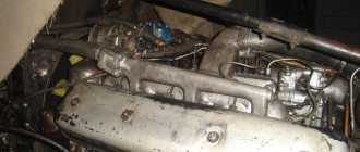
On the D-245 engine of the ZIL-5301 Bychok, GAZ-3309, MAZ-4370 Zubrenok cars, fuel injection pumps-773 are installed.
The high-pressure fuel pump is a block design consisting of four pump sections in one housing, having a cam drive of plungers and spool-type dosing of cyclic fuel supply. TNVD-773 is designed to supply metered portions of fuel under high pressure into the combustion chambers of diesel cylinders at certain points in time. The fuel pump camshaft is driven from the diesel crankshaft through distribution gears.
The relative position of the fuel pump drive gear and the drive coupling half is fixed by tightening the nuts installed on the coupling half studs. The tightening torque of the nuts is 35…50 Nm.
The D-245 high-pressure fuel pump is combined into one unit with an all-mode regulator and a piston-type fuel priming pump.
The regulator has a fuel supply corrector, an automatic fuel enricher (at starting speeds) and a pneumatic smoke limiter (boost corrector). The booster pump is installed on the fuel injection pump housing D-245 and is driven by the cam shaft eccentric.
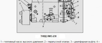
The working parts of the pump are lubricated with flowing oil coming from the diesel lubrication system. The oil is drained from the pump housing into the diesel crankcase. The newly installed pump on a diesel engine must be filled with oil in the amount of 200.250 cm3. Fill oil through the oil drain hole pos. 30 (Fig. 1).
Fig. 1 – Fuel pump TNVD 773 diesel D-245
Maintenance of the high pressure fuel pump TNVD diesel engines D-245
During operation of the high-pressure fuel pump 773, when the main parts wear out, its adjustment parameters are violated. Injection pump lubricant D-245 is centralized from the diesel lubrication system through a special oil line. The required oil level in the pump crankcase is set automatically.
To reduce wear of precision parts, it is not allowed to operate the injection pump without a filter element or with a clogged fine fuel filter. It is also not allowed to work with fuels that have a high water content.
If necessary, and also every 120 thousand km, it is necessary to remove the pump and check it on a stand for compliance with the adjustment parameters, as well as the setting angle of advance of fuel injection on a diesel engine. If necessary, make appropriate adjustments.
Adjustment and control of fuel injection pump 773 for the setting angle of fuel injection advance on the D-245 engine
In case of difficulty starting a diesel engine, smoky exhaust, as well as when replacing or installing a fuel pump after checking it at a stand every 120 thousand km or repairing a diesel engine, be sure to check the installation timing of the fuel injection on the diesel engine.
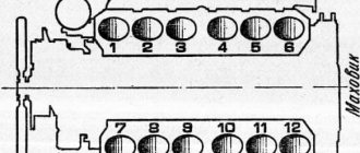
Check the installation angle of fuel injection advance for injection pump 773 of the D-245 engine in the following sequence:
— set the piston of the first cylinder on the compression stroke 40-50 before TDC;
— set the regulator control lever to the position corresponding to the maximum fuel supply;
— disconnect the high-pressure pipe from the fitting of the first section of the injection pump and instead connect a control device, which is a piece of high-pressure pipe 100.120 mm long with a pressure nut at one end and the other end bent to the side by 150...170° in accordance with the figure 24;
— fill the fuel pump with fuel, remove air from the low-pressure system and create excess pressure with a manual pump until a continuous stream of fuel appears from the control device tube;
- slowly rotating the crankshaft of the D-245 diesel engine of the ZIL-5301 Bychok, GAZ-3309, MAZ-4370 gear clockwise and maintaining excess pressure in the pump head (with a bleeder pump), monitor the flow of fuel from the control device.
— At the moment the fuel flow stops (up to 1 drop per 10 seconds is allowed), stop rotating the crankshaft;
— in accordance with Figure 2, unscrew the retainer from the threaded hole of the rear sheet and insert it with the back side into the same hole until it stops in the flywheel, while the retainer must coincide with the hole in the flywheel (this means that the piston of the first cylinder is installed in the position corresponding to the installation fuel injection advance angle.
If the latch does not coincide with the hole in the flywheel, adjust the injection pump 773, for which do the following:
— remove the hatch cover in accordance with Figure 3;
— align the lock with the hole in the flywheel, turning the crankshaft in one direction or another;
— loosen the nuts securing the fuel pump drive gear by 1.1.5 turns;
— using a wrench, turn the fuel pump shaft counterclockwise by the nut until the pins stop against the edge of the groove of the fuel pump drive gear;
— create excess pressure in the head of the fuel pump until a continuous stream of fuel appears from the tube of the control device;
— turning the pump shaft clockwise and maintaining excess pressure, monitor the flow of fuel from the control device;
— at the moment the fuel flow stops, stop rotating the shaft and fix it by tightening the nuts securing the drive coupling half to the drive gear.
Recheck the timing of the start of fuel supply. Disconnect the control device and reinstall the high pressure pipe and manhole cover. Screw the fastener into the hole in the back sheet.
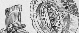
1 – hatch cover; 2 – nut; 3 – hairpin; 4 – special nut; 5 – drive coupling half; 6 – fuel pump drive gear
Checking diesel injectors D-245 for injection start pressure and fuel atomization quality
Fig. 4 – D-245 engine injector
1 – nozzle body; 2 – adjusting washer; 3 – spring; 4 – nozzle rod; 5 – spacer; 5 – sprayer nut; 7 – sprayer; 8 – sealing ring.
Check the injectors every 120 thousand km. Remove the injectors from the diesel engine and check them on a stand. The injector of the fuel pump TNVD 773 is considered to be in working order if it sprays fuel in the form of a mist from all five holes of the nozzle, without separately flying drops, continuous streams or thickenings.
Installation of injection pump, injectors, high and low pressure pipes D-245
The injection pump mating plate must be clean; nicks and other damage to the slab are not allowed.
The fuel pump gasket must not show any visible damage.
When installing the fuel pump, you must align the marks of the fuel pump drive gear and the splined flange.
The splined flange of the fuel pump gear must fit freely, without jamming, onto the splines of the fuel pump shaft bushing.
The fuel pump gear flange mounting bolts must be tightened to a torque of 18…25 Nm.
When installing the fuel pump, be sure to check the fuel injection advance angle.
This is done in the following sequence:
1. Set the regulator control lever to the position corresponding to the maximum fuel supply.
2. Disconnect the high-pressure tube from the fitting of the first section and connect the momentoscope instead (Fig. 1).
3. Turn the diesel crankshaft clockwise with a wrench until fuel without air bubbles appears from the glass tube of the momentoscope.
4. Remove some of the fuel from the glass tube by shaking it.
5. Turn the crankshaft counterclockwise by 30...40°.
6. Slowly rotating the diesel crankshaft clockwise, monitor the fuel level in the tube; when the fuel begins to rise, stop rotating the crankshaft.
7. If the latch does not coincide with the hole in the flywheel (Fig. 2), make adjustments by doing the following:
1. remove the hatch cover;
2. Unscrew bolts 1, 2 and 3 (Fig. 3) and loosen bolt 3 by ½…1 turn (do not unscrew the bolt);
3. align the locking rod 2 (see Fig. 2) with the hole in the flywheel, turning the diesel crankshaft in one direction or the other; Using a wrench, turn the fuel pump shaft and splined flange by the nut until the fuel begins to rise in glass tube 1 (see Fig. 1) of the momentoscope;
4. install bolts 1,2 and 3 (see Fig. 3) into matching holes, trying to position them as evenly as possible around the circumference;
5. first tighten bolt 3, then bolts 1 and 2;
6. Reinstall the high-pressure tube and remove the locking rod from the hole in the flywheel;
7. Reinstall the hatch cover.
The alignment of the splines of the fuel pump bushing and the splined flange when installed on a diesel engine is ensured by turning the diesel crankshaft or the pump camshaft.
Cost of injection pump and components.
A new fuel pump will cost the buyer 25-50 thousand rubles, depending on the manufacturer. Let's take, for example, the MOTORPAL company - fuel injection pumps produced by it have a price of 25-35 thousand rubles.
It is also worth mentioning the approximate cost of the main spare parts that may require replacement, which are adequate for the current market: - nozzles (1500-3000 rubles / piece); - installation plate (3000-5000 rubles); — fuel injection pump drive gear (3000-5000 r); — fuel injection pump gear shaft for D-245 (3000-5000 r); — high pressure fuel line (up to 1000 r); — fuel pump (1500-3000 r).
Checking and adjusting the setting angle of fuel injection advance on diesel engines D-245.7, D-245.9, D-245.12S
3.4.16.1 In case of difficulty starting a diesel engine, smoky exhaust, as well as when replacing and installing a fuel pump after testing on a bench after 6 TO-2 or repairs, be sure to check the setting angle of fuel injection advance on a diesel engine.
3.4.16.2 Check the installation angle of fuel injection advance using a type 773 fuel pump in the following sequence:
— set the piston of the first cylinder on the compression stroke 40-50 ° before TDC;
— set the regulator control lever to the position corresponding to the maximum fuel supply;
— disconnect the high-pressure tube from the fitting of the first section of the pump and instead connect a control device, which is a piece of high-pressure tube 100 to 120 mm long with a pressure nut at one end and the other end bent to the side by 150 ... 170 ° in accordance with picture 24;
1-pressure nut; 2-high pressure tube.