On new tractors, the ignition is calibrated at the factory. Optimally adjusted operating settings allow owners to forget about the need to adjust the ignition at MTZ for several years. But over time, when parts wear out, are removed for troubleshooting and repair, and then put back in, they will need to be recalibrated.
How to adjust the ignition on MTZ? How to set the parameters correctly for the most efficient operation of the engine? How to install the ignition on MTZ old and new models? We will consider these and other questions later in the article.
Ignition of diesel fuel.
The piston compresses the air in the combustion chamber. The piston group allows you to create compression in the combustion chamber above 25 var. If this happens. The temperature of the compressed air rises to 700-900 degrees Celsius.
Heating the air in the combustion chamber
The air is heated. Because during compression the distances between air molecules decrease. Molecules are in constant motion. And the smaller the distance between them. the more often they collide with each other. As a result, a large amount of kinetic energy is released. Which turns into heat. The greater the pressure on the air, the smaller the distance between the molecules. The higher the temperature of the compressed air rises.
How does ignition occur?
The compressed air is heated to a temperature of 700-900 degrees. At the moment when the piston begins to approach top dead center. The injector injects fuel under pressure. The fuel is sprayed into small droplets. The movement of the drop begins to evaporate and a cloud of vapor forms around it. The ignition temperature of diesel fuel is 350 degrees Celsius. That is, at a compressed air temperature of even 500 degrees. Fuel vapors are guaranteed to spontaneously ignite. And they begin to expand from combustion. Pressure is created in the cylinder. By the time the piston approaches top dead center. The fuel will ignite completely and create maximum pressure in the combustion chamber. This pressure will do the engine work. As the piston moves away from top dead center, the fuel burns out. Thus creating additional pressure on the piston.
The quality of fuel combustion is largely determined by the pressure with which fuel is injected into the combustion chamber. The faster and more efficiently the fuel burns, the higher the pressure it creates. The higher the spray pressure in the nozzles. The smaller the droplets and the faster they move. Accordingly, they burn faster. Therefore, with the same volume of the combustion chamber, it is possible to achieve an increase in engine power by increasing the fuel injection pressure.
Adjusting the fuel pump
One of the most important measures for servicing the fuel pump of the MTZ tractor is its adjustment. If it is performed correctly, the owner of the equipment will be able to avoid damage to the pump and other structural elements. Adjustment manipulations are carried out using a special stand, as well as the necessary tools:
- instruments that allow you to measure shaft rotation speed;
- disk for determining fuel supply;
- measuring containers for controlling fuel volumes;
- drive and variator, which are capable of smoothly changing rotation speed.
Speed indicators are adjusted using a bolt located in the product body, which is responsible for the degree of tension of the control spring. Screwing in the bolt leads to an increase in performance, and unscrewing it counterclockwise, on the contrary, will reduce the speed. The fuel supply is adjusted using a special sleeve, which works on a similar principle. For uniform feeding, you should use the nominal edge, which is also located on the body.
Trouble-shooting
There are several of the most common malfunctions that owners of MTZ tractors most often encounter. Since the price of the fuel pump is low, the technician can completely replace it if desired, but it will be much more economical to fix the breakdowns on his own.
The most common breakdown is wear of a pair of plungers , which is due to the low quality of the fuel and the abundance of impurities in it. For repairs, you will need to restore or replace damaged elements. To avoid damage, the fuel filter should be cleaned and replaced regularly.
Water hammer often leads to breakdowns due to the appearance of water in the system. If a problem occurs, you will need to thoroughly clean the element from any remaining moisture, and then restore its tightness.
Adjustment procedure
Conversion of torque units.
units of torque, units of torque, units of torque, units of torque. table The need to install injection arises when replacing a high-pressure fuel pump (HPF) or installing it after repair, as well as after repairing the piston group of a diesel engine. The adjustment is carried out provided that the fuel equipment, injection pump and the adjusted gas distribution mechanism of the diesel engine are in good working order. The installation process consists of the sequential operations described below.
Installing the first cylinder on the compression stroke
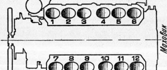
On the right side, in the direction of travel of the machine, in the wall of the engine mounting to the clutch housing, above the longitudinal beam of the tractor frame near the oil filler neck, there is an installation dipstick. With its short threaded part it is screwed into the mounting wall and with its long threadless part it is installed outside. If it is necessary to install the first cylinder in the “compression” stroke position, the dipstick is installed in the hole, resting its long part against the engine flywheel. Slowly turning the diesel crankshaft, find the position at which the probe will fall into the hole on the flywheel and enter the body of the part completely by 4-5 cm
It is important not to confuse the installation hole with the technological, balancing drillings of the flywheel, which are much shallower in depth. The found position corresponds to an advance of 26 ̊ before the piston of the first or fourth cylinder approaches TDC
This position corresponds to the technical requirements of D 240 for setting the start of fuel injection into the cylinder during the “compression” stroke. To determine which of the cylinders in the first or fourth the “compression” stroke has begun, you need to remove the valve cover. A pair of closed valves will indicate in which of the two cylinders (first or fourth) the “compression” stroke has begun.
Installation probe for D 240
Disconnecting the pump drive
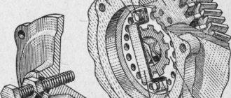
To establish synchronization of the engine and fuel injection pump operating cycles, you need to understand that the pump drive connecting through the engine timing gears must be disconnected. The drive is connected by connecting the holes of the pump drive gear 4 with the adjusting holes of a special washer 5 along the perimeter through a splined bushing fixed to the pump shaft. Access to the drive is achieved by opening the front cover 8 of the pump. To disconnect, unscrew two fastening bolts 3 with strip 7 and remove the adjusting washer from the splined sleeve. In this position, the rotation of the shaft cranks will not be transmitted through the camshaft gear drive to the pump shaft 6.
Injection pump drive device D 240
Momentoscope installation
After identifying the cylinder in the “compression” stroke and disconnecting the drive on the fuel pump, install a torque scope on the corresponding supply section of the pump instead of the high pressure pipeline connecting the section to the cylinder injector. To more accurately determine the beginning of the injection moment, set the manual fuel supply lever to the maximum position. To determine the moment of injection, if necessary, pump the fuel equipment with a manual pump pump, removing air from the system.
Injection installation operations
Determining and setting the timing of fuel supply
By turning the injection pump camshaft clockwise and observing the fuel level in the device tube, you need to determine the position of the pump shaft at the moment fuel supply begins in this section. The moment the supply begins will be the position at which the fuel level in the device tube begins to rise, shifting as a result of the start of the supply cycle, running the injection pump shaft cam onto the plunger pusher of the corresponding section
It is very important to determine, by observing the fuel level in the momentoscope, the beginning of this cycle
Injection pump drive with adjusting washer assembly Adjusting washer for the injection pump drive Splined sleeve in the injection pump drive Engine installation probe D 240
Setting the position of the pump drive shim
Having determined the moment of the start of injection on the section by the position of the injection pump shaft, connect the pump drive by installing a splined adjusting washer on the splined bushing. The fastening bolts with the strip are screwed into the most aligned holes of the washer and the flange of the pump drive gear. In this case, the bolts should fit freely without snagging. Then install the pump cover by tightening the three bolts around the perimeter of the cover. The axial clearance of the drive gear is adjusted using the adjusting central screw in the cover. To do this, unscrew the lock nut of the screw, screw it all the way into the washer bar and unscrew it 1/3 or 1/2 turn, after which the position is fixed with a lock nut.
Features of ignition adjustment on different tractors
How to adjust the ignition on MTZ 80 and 82
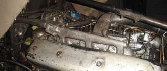
The MTZ 80 and 82 tractors are equipped with the D-240 diesel engine and its modifications. Let's figure out how to adjust the ignition in this case.
Step 1: Set the injection pump to the beginning of the injection moment
The need to set the ignition usually appears after removing the fuel pump. Accordingly, before adjusting the ignition, you must first put back the fuel injection pump.
The main design feature of MTZ 80 and 82 with D240 is the presence of an adapter plate, through which the fuel pump shaft is connected to the drive gear. The adapter plate is mounted on the injection pump shaft using the internal spline.
There are many through holes made along the edges of the adapter plate. They are necessary so that the plate can be aligned with the holes on the drive gear after adjusting the position of the fuel pump shaft.
To determine the position of the injection pump shaft, perform the following steps:
- Diesel is pumped into the fuel pump.
- The fitting with the outlet tube is unscrewed.
- Using a pump, pressure is created in the injection pump until air bubbles stop escaping.
- After removing the air, rotate the fuel pump shaft until liquid appears from the hole in the 1st cylinder section.
The moment the required pressure level is reached in the tube that goes to the injector is the beginning of fuel injection.
The cam on the fuel pump shaft has an elliptical cross-section, so when rotated in a certain position it presses on the plunger. As a result, the hole through which fuel enters the plunger cavity is blocked, and high pressure is created in it. When determining the injection angle, you need to catch the position of the plunger when it starts to move and has just blocked the slot for supplying diesel fuel.
To correctly adjust the ignition on an MTZ 80/82 with a D240 engine, you do not need to use any specialized tools or sensors, because you can determine the moment when fuel injection begins visually. While turning the fuel pump shaft, you need to note the moment when diesel fuel appears in the section of the first cylinder. Next, the shaft must be moved back a little and slowly turned clockwise again until the fluid begins to move. The injection pump shaft must be left in this position.
Step 2: Advance the crankshaft
To set the ignition on a MTZ 80 or 82 tractor, the next step is to set the piston of the first cylinder to the ignition timing. The sequence of actions is as follows:
- Turn the crankshaft until the rocker arms of the 1st cylinder stop moving - in this position they will stop putting pressure on the valves and they will be closed.
Important : The operating cycle includes two lifts of the piston to top dead center. We need to catch the piston when moving to TDC on the compression stroke, when the valves are closed and the rocker arms are not moving.
- When you have tracked the desired moment of piston movement and the valves have closed, you need to unscrew the adjusting bolt, which is located on the rear wall of the engine. It needs to be turned over and inserted into the hole with the reverse side, continuing to rotate the crankshaft until the bolt slips down, hitting the hole in the flywheel. In this position, the bolt will need to be tightened to secure the crankshaft.
Step 3: Install the Adapter Plate
The transition plate or ripple is a disk with many holes. The plate is installed on the splines of the fuel pump shaft so that its holes coincide with the holes on the gear.
Advice : Before removing the injection pump, it is advisable to put a mark on the gear and adapter plate, so that later during assembly you do not waste time selecting the position of the ripple.
But even with a mark, the plate may move relative to its original position. The reason may be wear on the timing gears or the installation of new parts when repairing the fuel pump. In any case, this does not mean that the hazel grouse was installed incorrectly: the main thing is that the holes match.
Once the adapter plate is in the desired position, it must be secured with bolts.
How to adjust the ignition on MTZ 82.1 and 1221
To set up the ignition on a new model MTZ 1221, 1221.3 or 82.1 with D-245 and D260 engines, you need to perform steps similar to those described above. However, there are still differences in ignition adjustment. They are due to the fact that on MTZ 1221 and 82.1 the connection of the fuel pump to the gear drive is carried out through a flange fixed on the injection pump shaft.
The connecting flange has three studs, which are not symmetrically placed. This is done to make it easy to find the desired position of the fuel pump when installing it. Actually, to install the injection pump, it is enough to get the pins into the holes.
The convenience of this approach is also that you can adjust the ignition on the MTZ by fine-tuning the fuel injection pump due to the fact that the holes have an elongated shape and the pins can be moved slightly clockwise or counterclockwise.
Step 1: Set the fuel pump to the beginning of the injection moment
Having put the injection pump in place after dismantling, you will have to fix the gear with the flange so that all three pins fit into the holes. Despite the fact that the holes have an elongated shape and allow you to slightly adjust the position of the pump, you should first secure the injection pump so that the studs are in the center of the holes.
Next, you need to fill the fuel pump with diesel fuel and pump it until the air is completely displaced. After this, you need to rotate the crankshaft until liquid appears from the section of the 1st cylinder.
Step 2: Set the crankshaft to advance the ignition
To adjust the ignition on a new MTZ 82.1 or MTZ 1221 with a D-260, you do not need to calculate whether the piston is in the compression stroke, since for these tractors the fuel pump shaft makes only one rotation per cycle. We need to catch the moment when injection occurs in the section of the first cylinder.
Having created pressure in the fuel pump, you need to unscrew the nuts that secure the injection pump flange and gear. After being released from the fastenings, the flange must be turned all the way to the left. To find the required shaft position, you need to slowly turn the flange clockwise until liquid begins to rise in the fitting of the first cylinder section. This will mean that fuel is injected into the first cylinder and the piston has reached TDC minus the ignition timing.
Removing air from the fuel injection system
Fuel injection system (injector)
Air bubbles in the fuel can impair the operation of the fuel injection pump or even make it impossible. In this regard, devices that are installed for the first time or are temporarily disconnected must be freed from air.
If the fuel priming pump is equipped with a hand pump, then it is used to fill the line, fuel filter and injection pump with fuel. In this case, the ventilation screws (1) on the filter cover and on the fuel injection pump must remain open until the escaping fuel contains no bubbles. Bleeding must be done every time the fuel filter is replaced or any work is done on the system.
During real-life operation, air is removed from the injection system automatically through the flow valve (2) on the fuel filter (continuous ventilation). A restrictor can be used instead of a valve if the pump does not have a flow valve.
Elimination of floating revolutions.
The barking of the engine occurs when the hazel grouse begins to walk in the splines of the injection pump shaft. Due to the slightest play of the hazel grouse and the fuel injection pump shaft, play is generated during engine operation. The pump, under the action of the plunger springs, begins to change the fuel injection angle and the engine barks.
All this can be eliminated in a simple way. We remove the ignition cover, unscrew the hazel grouse, and pull it out from the landing site. Using a welding machine, we weld small spots into the slots of the hazel grouse. Next, using a diamond file, we adjust it to the size of the pump shaft so that the hazel grouse fits tightly and there is no play.
This way we will remove the floating speed. If this does not help, then you will have to contact a fuel injection pump repair specialist, which means there is another problem, the pump cracks in the injection pump housing have worn out. The masters will replace them for you. Here are 2 reasons for the floating speed of the D-240 engine that I know.
Source
How to properly install and adjust the ignition on MTZ-80 and MTZ-82 - Agrovesti.net
How does the mpi multipoint fuel injection system work?
The ignition on a tractor is very important, because thanks to it the mechanisms are put into action. The ignition is initially adjusted in the workshops.
In turn, the tractor has to work in difficult conditions, including difficult weather, which subjects the device to heavy load. As a result, breakdowns may occur, including magneto breakdowns. In such a situation, certain knowledge and skills will be useful.
If we consider the MTZ-80 and MTZ-82 tractors, then these common tractor models are equipped with the M124-61 mechanism. It is called a magneto and rotates to the right. This device has an ignition timing angle of twenty-seven degrees. When the mechanism rotates, a rigid half-coupling is engaged. It is supplied with an impulse by the PD-10 starter gear.
The magneto design consists of three components:
- transformer,
- breaker mechanism,
- rotor part.
The rotor is the generating element. It produces a variable current and directs it to a reliable and robust transformer. In turn, it increases the current value to even greater power - from 9 to 14.95 kW. Next, the current is addressed to the breaker. This action is a specific process, let's consider it. During rotary rotation, typical alternating voltage occurs. It is transmitted by magnetic flux to the transformer. The secondary winding of the magnetic flux produces a higher voltage. At the moment when the voltage value reaches its maximum, the breaker “removes” it from the first winding. As a result, the magnetic flux decreases, and electricity is generated in the electrodes of all spark plugs. Sparks occur and ignite the incoming fuel.
To perform repairs, you must perform the following steps. You need to remove the wires from the spark plugs and unscrew them. Next, a metal rod is inserted into the empty hole. The rod must be sterile, its radius must be less than the radius of the candle holes. We turn the main engine shaft in the direction of the clock hand. This action must be done until the piston is at top dead center. Then we turn the main engine shaft counterclockwise. This action must be done in such a way that the piston position is 5-6 millimeters below top dead center. Next, the breaker cover is removed from the magneto. The flywheel must be rotated and installed closer to the cam contact space. We push the protrusions of the magneto coupling half into the grooves of the drive gear. Be sure to tighten the bolts to secure the magneto itself. As a result, return the cover of the M124-61 mechanism to its original position, and the wires can now be reconnected to the engine spark plugs themselves.
In order for the magneto element to work properly, it is necessary to inspect it, as well as study the elements of the ignition system. After every 960 hours of engine operation, you need to look at the contacts of the magneto interruption mechanism, as well as the size of the gaps between them. During operation, soot, scale, and dirt deposits are most often created. As a result, it is necessary to clean the contacts, even if “Belarus” is idle. There is a special file for this operation. It does not leave abrasive chips or dust from metal particles.
After almost one and a half thousand hours of engine operation, it is necessary to check the condition of the cam lubrication. If there is not enough lubrication, you need to add a few drops of turbine oil. If the equipment is idle, it is necessary to lubricate the magneto rotor bearings every two years. To do this, it is necessary to remove the mechanism, disassemble it, and remove the remaining obsolete lubricant. Next, the device needs to be wiped and washed in gasoline.
agrovesti.net
Design and operation of magneto PD-10UD
Tractors produced by the Minsk Plant are mainly equipped with an M124-B1 magneto, which has right-hand rotation due to a flanged half-coupling rotated by a PD-10 gear, and a 27-degree ignition timing angle.
To perform its functions, the M124-B1 magneto is equipped with the main mechanisms that ensure its operation: a rotor, a transformer and an interrupter unit.
The alternating current generated by the rotor assembly during its rotation is increased by the secondary winding of the transformer to its value of –10-15 kW and supplied to the breaker assembly. The formation of a spark that ignites the fuel in the spark plug occurs at the moment the breaker transmits a current that has reached its maximum level in the primary winding of the transformer.
Operating principle of the injection advance device
The injection advance device is driven by a toothed gear, which is installed in the engine timing gear drive housing. The connection between the input and output for the drive (hub) is made through locking pairs of eccentric elements.
The largest of them, the adjusting eccentric elements (4), are located in holes in the locking disk (8), which, in turn, is bolted to the drive element (1). Compensating eccentric elements (5) are installed in the adjusting eccentric elements (4) and are guided by them and a bolt into the hubs (6). On the other hand, the hub bolt is directly connected to the hub (2). The weights (7) are connected to the adjusting eccentric element and are held in their original positions by springs with variable stiffness.
Device
When planning to repair the MTZ fuel injection pump, you should familiarize yourself in more detail with the design of such an element. It is distinguished by a minimum number of elements and high reliability, which makes it possible to significantly simplify the procedure for adjusting the pump, as well as troubleshooting. The main components of this unit are:
- plunger pairs;
- frame;
- pressure type valve;
- pushers;
- camshaft;
- plunger drive mechanism.
The pump head and housing are a single element made of high-strength aluminum alloy. The design of the unit provides that a special plate is placed on the front part of the housing, which is used to mount the product directly on the engine. When figuring out how to remove the injection pump from the MTZ 82, it should be noted that to do this it is enough to remove the mounting bolts.
The back of the plate is equipped with a special flange, which is used to install the regulator. The principle of operation of the product is extremely simple, it involves the following algorithm of actions:
- The cam shaft begins to rotate, lifting the pusher with the help of a roller.
- The pusher moves down together with the plunger.
- Fuel fills the space in the sleeve vacated by the descent of the plunger.
- When the element returns to its original state, pressure is created, due to which, with the help of a valve, a portion of fuel flows through the nozzles.
This cycle is repeated at certain intervals, which allows you to maintain the fuel level necessary for proper engine operation.
Fuel pump diagram
How to set the ignition on a diesel engine
How to set the ignition on a diesel engine? The need to solve this problem may arise in one of the following cases:
After the timing belt was replaced.
After the high pressure fuel pump has been removed or replaced. After this, it may be impossible to find the marks where the pump pulley was installed. Therefore, before starting repairs, it is better to update the tags, so as not to suffer with the ignition later. You can do this in different ways, such as applying paint around the mark.
But if you still have a problem with setting the ignition, you can go in two ways.
How to set the ignition on a diesel engine. Method No. 1
The first way is to set the ignition using the trial and error method. It should be noted right away that this method is not optimal. Moreover, if the ignition is set for too long in this way, it does not add survivability to the engine and reduces its service life. But this method is still worth considering.
How it's done
• Once the pulley is installed, an attempt is made to start the engine. If the diesel engine does not start at all, the pump pulley rotates in relation to the belt by 3-5 teeth. An attempt is made again to start the engine.
• If the engine starts after several movements, you need to understand how a diesel engine works. If you hear a knock, you need to turn the pump pulley 1-2 teeth in the direction opposite to the rotation of the pulley.
• If there is a lot of smoke coming out of the exhaust pipe when the engine is running, this means that there is a delayed injection of diesel fuel. In this situation, the pump pulley must be turned one tooth forward in relation to the belt.
• If all these actions do not help, you will have to loosen the pump and by turning it around the axis, try to achieve normal operation of the diesel engine. Ideally, a diesel engine should operate on the edge of detonation levels. As soon as detonation begins, it becomes audible through the sound of the engine.
How to set the ignition on a diesel engine. Method No. 2
The second way of setting the ignition is more correct from a technical point of view.
How it's done
• The high pressure pipe from the injector of the 1st cylinder is removed.
• A transparent plastic tube is placed over the high-pressure tube (tubes are sold at any hardware store). The transparent tube should be vertical.
• The ignition is turned on and the pump pulley is rotated with the key. As you rotate, we determine the upper point of the fuel position in the tube, and accordingly in the nozzle. The pulley must be rotated very slowly and smoothly, without sudden jerks.
• Once the desired point is found, a mark is placed on the pulley.
• After this, the positions of the camshaft and crankshaft are set using the marks.
You can set the timing of diesel fuel injection even more accurately by moving the fuel pump. But if the pump was not removed before repair, then there is no point in touching it.
If all these steps seem too complicated, then it makes sense to contact an experienced mechanic or an appropriate service whose specialists know perfectly well how to set the ignition on a diesel engine.
But in order to eliminate the possibility of setting the ignition again, it is necessary to update the marks before any repairs related to removing the belt or injection pump.
Starting motor transmission gearbox
The function of the mechanism is to switch on the rotation transmission to the diesel flywheel, as well as automatically turn it off after starting the tractor engine. The starter transmission housing is attached to the rear wall of the diesel engine and is connected to the lower plate of the distributor gearbox, receiving rotation from the intermediate gear. The mechanism is lubricated with diesel oil, filled to the level of the control hole in the gearbox housing. The level is monitored every 240 hours of operation. The oil is changed at intervals of 960 hours of tractor operation.
Starter clutch reducer assembly
The device includes the following mechanisms:
- friction clutch gear
- roller overrunning clutch automatic release
- Bendix is a mechanism that controls a gear that meshes with a diesel flywheel.
- levers and clutch engagement drive,
PD-10 starting motor transmission device
With the help of a driver, a gear sliding along the splines of the shaft engages with the rim of the engine flywheel. The on position is held by latching weights, which are fixed by spring force. When the starting engine is running, the clutch gear does not transmit rotation to the shaft as the driving clutch discs are not connected to the driven ones.
The clutch drive drum is riveted to the gear and rotates together with the drive disks, since the drum leads fit into the grooves of the disks. The driven ones are connected by their protrusions to the overrunning clutch bushing and rotate with it.
The overrunning clutch interacts directly with the shaft and is housed in a separate bushing. The bushing itself is both the driven part of the clutch assembly and the driving race of the overrunning clutch. The operating principle consists of jamming four symmetrically located rollers spring-loaded through pushers into the wedge-shaped recesses of the bushing.
Engaging the starting motor clutch
By smoothly moving the control lever to position II, the movable stop 26, interacting with the engagement drive through the ring gear, rotates and runs into the protrusion of the fixed stop 27. In this case, the pressure plane of the stop shifts along the axis to the right, connecting the clutch disks. The rollers 25 of the overrunning clutch jam, and shaft 24 begins to rotate, moving it onto the Bendix gear in engagement with the diesel flywheel 23.
Control PD 10 tractor MTZ 80
Automatic overrunning clutch disengagement
Having started the diesel engine, with an increase in rotation speed, torque begins to be transmitted from the flywheel, trying to drive the crankshaft of the starter through the transmission shaft with the power of the running diesel engine. In this case, the clutch rollers, due to the higher shaft speed obtained from the diesel engine in relation to the overrunning clutch bushing, compress the springs and exit into the wide part of the grooves. As a result, the coupling sleeve is automatically disconnected from the shaft, and the reverse transmission of rotation to the starting motor stops.
Design of the injection advance device
The injection advance device for an in-line injection pump is installed directly at the end of the injection pump cam shaft. The main differences between injection advance devices are open type and closed type.
The closed-type injection advance device has its own lubricating oil reservoir, which makes the device independent of the engine lubrication system. The open design is connected directly to the engine lubrication system. The body of the device is screwed to the gear, and the compensating and adjusting eccentrics are installed in the body so that they rotate freely. The compensating and adjusting eccentrics are guided by a pin, which is rigidly connected to the body. In addition to lower price, the “open” type has the advantage of requiring less space and lubricating more efficiently.
Checking the injection advance angle
After starting, check the operation of the engine in different modes. In case of unstable or hard operation at high speeds, knocking and detonation, black smoke and incomplete combustion of fuel, the injection timing is checked and adjusted.
Install the momentoscope on the first section of the pump and monitor the coincidence of the moments when the probe enters the hole in the flywheel and the start of fuel supply to the pump section. The moment of supply before the probe coincides indicates a large advance angle, but if the fuel supply does not start when the probe hits, the injection is late. If the injection timing does not match, correction is made by turning the injection pump shaft. Also open the pump cover, unscrew the two bolts securing the adjusting washer with the bar. To increase the advance angle, turn the shaft clockwise, and in the opposite direction, reduce the injection advance angle. Moving the shaft position by one adjustment hole on the washer corresponds to 3 turns of the diesel crankshaft. By turning the injection pump shaft in the desired direction until the holes on the washer and the gear flange coincide, the injection angle is changed. Assembly is carried out in the same order - install the washer with bolts on the bar in the matching holes.
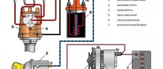
Operating principle of the ignition system
The ignition system is used for reliable and timely ignition of the combustible mixture entering the cylinder. It consists of a magneto, a spark plug and a high voltage wire.
The operating principle of this element is quite simple and reliable at the same time - when the working mixture enters the cylinder of the starting engine, it is ignited by means of an electric charge formed between two electrodes on the spark plug. For the highest quality charge, a fairly high voltage is required, approximately 10-15 kV, which is created in a special device - a magneto, which combines a number of functions - a breaker, an alternating current generator and a transformer.
Classic fuel injection system.
Based on the use of a high pressure fuel pump. It distributes fuel pressure across the cylinders. Depending on the operating pattern of a given engine. The injection pump cavity is filled with fuel using a booster pump. Which is located on the fuel injection pump housing and is driven by the injection pump shaft. The booster pump pumps fuel from the tank and directs it to fine filters. And then the fuel enters the injection pump. The high pressure fuel pump cavity fills. It contains plunger pairs. They grab fuel. And they create high pressure. Which is supplied to the injectors. The nozzle is designed like this. Which accumulates the resulting pressure from the plunger. And when the required pressure is reached, it opens channels through which fuel is sprayed. This is a classic scheme. The pump allows you to change the engine crankshaft speed. By changing the amount of fuel supplied to the cylinders.
In addition, some pumps have the ability to change the ignition timing. Through the use of centrifugal weights. As the engine speed increases, the pump shaft shifts relative to the drive. This system is designed for average engine performance. At various expected operating modes. And cannot influence unintended loads. Such as a decrease or increase in transported cargo. Descent ascent. Road surface. The amount of fuel will correspond only to the required engine speed.
Accordingly, there will either be not enough fuel. Or an excessive amount is served. As a result, complete combustion of fuel in the cylinders is not achieved, and as a result, low efficiency. Negatively affecting fuel consumption, engine power and environmental performance. Environmental requirements ultimately turned out to be the main factor in the evolution of the injection system. The better the fuel burns in the combustion chamber. This creates less harmful emissions into the environment. Accordingly, the more efficient the combustion of fuel, the better the engine performance. The designers have been improving the diesel fuel injection system for a long time.
But all of these were usually variations on the fuel injection pump theme. Fuel injection was carried out in full. Therefore, when the diesel engine is running, a characteristic knock is heard. The fuel supplied to the cylinder ignites, the pressure increases at TDC to its maximum value. And a strong blow occurs.
A modern diesel engine injection system is capable of delivering injection in several stages. How to pre-ignite fuel. Preliminary injection of fuel is called pilot injection. When the piston passes the ignition timing mark, fuel is pre-injected. A small amount of fuel ignites. Then some more fuel is given.
There can be up to 5 such preliminary injections. After the pilot injection, the main injection occurs. Already into burning fuel. The bulk of the fuel ignites faster and burns more efficiently. As a result, the engine runs smoothly without harsh shocks. And more complete combustion of fuel ensures low emissions of harmful substances and increased engine power characteristics. Such an injection can only be provided by the Comon Rail system.
Why is early ignition installed?
To ensure that diesel fuel ignites before the piston reaches top dead center, the ignition angle must be advanced. As we wrote earlier, the optimal angle is 26 degrees. But sometimes the piston can reach TDC within 11-27 degrees of crankshaft rotation.
During the compression of the air mixture, its temperature rises to 700-800 degrees Celsius. And by the time fuel is injected, the temperature of the compressed air is so high that it ignites the diesel engine. Thus, when the piston reaches TDC, the already burning air-fuel mixture is compressed. The gases released during the process create excess pressure and push the piston out.
To obtain maximum pressure, i.e. To have the greatest impact when running a diesel engine, it is necessary to compress the already burning mixture. To do this, some engines even have a mechanism for supplying already ignited fuel. Due to this, engine power increases.
There are no universal rules on how to adjust the ignition on a MTZ tractor, since engines with different ignition timing are installed in Belarus. They are placed depending on the location of the mounting pulley located on the rear of the motor. To set the ignition on the MTZ, you will need to get into a special hole in the flywheel. If this is done, the piston will be positioned exactly at the required advance angle. After this, you will only need to adjust the ignition on the fuel pump, setting the start of diesel injection with the plunger of the first cylinder.
Injection pump lubrication
It is best to connect the injection pump and regulator to the engine lubrication system, because With this form of lubrication, the injection pump remains maintenance-free. Filtered engine oil is supplied to the injection pump and regulator through the discharge line and the inlet channel through the roller tappet hole or using a special oil supply valve. In the case of a base or frame fuel injection pump, the lubricating oil is returned to the engine via the return line (b).
In the case of flange mounting, the return of lubricating oil can occur through the camshaft bearing(s) or through special channels. Before turning on the injection pump and regulator for the first time, they must be filled with the same oil as the engine. In the case of an injection pump without a direct connection to the engine oil system, oil is poured in through the cover after removing the air bleeder cap or filter. The oil level in the pump is checked by removing the oil level screw on the regulator at the intervals prescribed by the engine manufacturer for changing the engine oil. Excess oil (an increase in the amount due to oil leakage from the lubrication system) must be drained, and if there is not enough oil, then add fresh oil. When the injection pump is removed or when the engine undergoes major repairs, the lubricating oil must be replaced. To check the oil level, injection pumps and regulators with a separate oil supply are equipped with their own dipstick.
Injection pump device for MTZ – 80, 82
UTN-5, as the fuel pump for the Belarusian brand of tractors is called, is made of durable aluminum alloy and is available in two possible installation options - left and right, depending on the design features of the flange mounting. Throughout the entire body, it is divided into two cavity parts by a special partition, where in the lower cavity there is a shaft with a pump drive, and in the upper cavity there are separate sections of this pump.
You can read the full detailed structure of the high pressure fuel pump of the D-240 engine below
Fuel pump with regulator:
1 – pressure fitting; 2 – clamps; 3 – spring; 4 – discharge valve; 5 – valve seat; 6 – gasket; 7 – plunger bushing; 8 – plunger; 9 – plug; 10 – ring gear; 11 – rotary sleeve; 12 – regulator cover; 13 – rack rod; 14 – spring lever; 15 – regulator spring; 16 – enrichment spring; 17 – main lever; 18 – corrector body; 19 – corrector rod; 20 – adjusting screw; 21 - intermediate lever; 22 – nominal bolt; 23 – bolt; 24 – regulator body; 25 – load axis; 26 – heel; 27 – coupling; 28 – heel axis; 29 – lever axis; 30 – regulator weights; 31 – thrust ball bearings; 32 – drain plug; 33 – cargo hub; 34 – shock absorber block; 35 – washer; 36 – bearing cup; 37 – oil deflector; 38 – control lever; 39 – cam shaft; 40 – plug; 41 – eccentric drive of the booster pump; 42 – flange for mounting the booster pump; 43 – adjusting washer; 44 – fastening plate; 45 – pump housing; 46 – oil supply hole; 47 – roller nut; 48 – splined bushing; 49 – mounting flange; 50 – pusher with roller; 51 – pusher adjusting bolt; 52 – spring plate (lower); 53 – plunger spring; 54 – spring plate; 55 – toothed rack; 56 – bolt for bleeding; 57 – channel for fuel removal; 58 – bypass tube; 59 – bypass valve body; 60 – plug; 61 – valve ball; 62 – hole for fuel supply; 63 – channel for fuel supply; 64 – cut-off hole; 65 – inlet hole of the plunger sleeve; 66 – pin; 67 – hatch cover; 68 – adjusting screw; 69 – gasket; 70 – filler plug; 71 – adjusting screw; 72 – corrector spring; 73 – tightening screw.
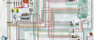
Here you can see the entire fuel system of the Belarusian tractor:
Diesel power system (diagram):
1 – muffler; 2 – air cleaner; 3 – coarse air filter; 4 – intake manifold; 5 – electric torch heater; 6 – fuel tank of the electric torch heater; 7 – drainage tube; 8 – high pressure tube; 9 – filler neck; 10 – fuel tanks; 11 – drain valve; 12 – fuel pipe; 13 – fuel coarse filter; 14 – fine fuel filter; 15 – tube from the fine filter to the fuel pump; 16 – tube from the sediment filter to the fuel pump; 17 – fuel pump regulator; 18 – fuel pipe from the booster pump to the fine filter; 19 – booster pump; 20 – bypass tube; 21 – fuel pump; 22 – nozzle; 23 – exhaust manifold; 24 – lower filter element; 25 – middle filter element; 26 – upper filter element.
At the upper cavity point of the UTN - 5 D-240 engines there are two longitudinal channels that form a square, one end of which is connected to the fine fuel filter, and the other, respectively, to the pump itself in the pump, where a bypass valve is mounted in the fitting.
We adjust the injection experimentally
Injection adjustment is made experimentally after installing the pulley. After installing the pulley, start the engine. If it does not start, then rotate the injection pump pulley relative to the timing belt by 2-4 teeth.
Start the engine again.
After the manipulations we have performed, it should start, listen to the operation of the motor. Obvious knocking sounds mean detonation; you need to turn the pump pulley in the direction 1-2 teeth opposite to its rotation. Thick gray smoke means late injection, then the pump pulley must be turned 1 tooth in the direction of its rotation.
If there are no changes for the better in the operation of the diesel engine, you need to rotate the pump around the axis. With such rotations it is necessary to achieve optimal operation of the unit. The best setting option would be to work in the mode before detonation knocks appear. They are very audible when the diesel engine is running.
The second method of the experimental method involves the following steps:
We unscrew the tube that goes from the pump to the injector on the first cylinder. Pull a transparent hose onto the removed end of the tube and place it in a vertical position.
Now you need to turn on the ignition and slightly turn the injection pump pulley. Rotate the pulley little by little, slowly and very carefully. At the same time, monitor the fuel level in the transparent hose. Determine the highest limit. When the diesel level is at the upper limit, make a mark on the pump pulley.
After this, the camshaft and crankshafts are set according to the marks. Start the engine and check its operation. If there are signs of improper injection, repeat the adjustment procedure again. If it still doesn’t work out, contact the service station, they will fix everything and, if necessary, adjust it at the stand.
That's all, friends, until we meet again, subscribe to the site update, if you haven't yet, share the link with your friends, if you haven't done so yet, there will be a lot more useful stuff.
Source
Adjusting the fuel injection pump on the engine
The fuel injection pump is synchronized with the engine using timing marks to start injection (closing the channel). These marks are located on the engine and on the fuel injection pump.
Typically, the engine's compression stroke is used as the basis (the reference point for injection timing adjustments, although other possibilities may be used for a particular engine model)
In this regard, it is important that the manufacturer's instructions are taken into account. In most cases, the timing mark for closing the channel is located on the engine flywheel, on the V-belt pulley or on the vibration damper
There are several possibilities for adjusting the injection pump and setting the correct value for the start of injection (closing the channel).
- The fuel injection pump is delivered from the factory in a form where its cam shaft is locked in a predetermined position. After installing the injection pump on the engine and strengthening it with bolts, when the crankshaft is in the appropriate position, the cam shaft of the injection pump is released. This well-tested method is inexpensive and is becoming more and more popular.
- The injection pump is equipped with a channel closing indicator at the end of the regulator, which must be aligned with the installation marks when the injection pump is installed on the engine.
- The injection timing advance device (clutch) has a mark for closing the hole, which must be aligned with the mark on the injection pump body. This method is not as accurate as the two described earlier.
- After the fuel injection pump is installed on the engine, a high pressure flow method is used at one of the pump outlets to determine the point (moment) of channel closure (i.e., when the plunger closes the fuel outlet channel). This "wet" method is also being actively replaced by method 1 and 2 described earlier.
Initial installation of the ignition grouse of the D-240 engine
1 Initial installation of the ignition grouse
2 Elimination of floating speeds
3 We set the ignition of ZIL-130
In order to initially install the ignition ripple on the D-240 engine. It is necessary to bring the piston of the 1st cylinder to TDC on the compression stroke. It can be done this way.
Take an electrode or a piece of wire and lower it into the hole under the nozzle until it reaches the piston. Using the valves on the head, it is necessary to catch the compression stroke and bring the piston to top dead center. When the electrode moves upward, turning the crankshaft with a wrench will catch the TDC. When we insert TDC we do the following.
Using a wrench, we turn the injection pump by the shaft on the pump, which secures the hazel grouse gear. We set the injection stroke, observing the fuel inlet from the first plunger.
When we have the piston in the compression stroke and the pump in the injection stroke, then we install the ignition switch in place and secure it with 2 bolts. This will be an approximate insertion of the ignition, and then, as the engine operates, at your discretion, set the ignition earlier or later by moving the 2 ignition adjustment bolts.
WATCH THE VIDEO
What is the injection pump used for?
The main difference between a gasoline unit is the ignition of the combustible mixture inside the cylinders. In a gasoline engine, the mixture is ignited by spark plugs. In a diesel engine, the mixture spontaneously ignites under compression. The injection pump is needed for the timely supply of diesel fuel to the cylinders at the moment of compression.
By design, injection pump pumps differ as follows: in-line type, main type and distribution type. In an in-line engine, diesel fuel is pumped into each cylinder from its own pair of plungers. The distributor provides all cylinders with one or two pairs of plungers. Mainline devices are used to pump diesel fuel into the fuel accumulator.
Remember, injection pump and injectors are the main elements of the diesel ignition system. They are present in most diesel units and are of the electronic type.
When it is necessary to adjust injection
At the factory there is a special machine for adjusting the injection pump. Therefore, it works well without adjustments. But, there are times when, after some repair work, you have to adjust the injection angle, for example:
- After replacing the timing belt
- You removed the fuel injection pump, and you cannot install its pulley according to the special marks.
- Any other unavoidable repair work that disrupts the injection angle adjustment.
Let me remind you, dear readers, that to fully adjust the fuel injection pump you need a special stand. Therefore, disassembling it into parts or turning all the screws on it is simply stupid. You will misadjust the device so much that later, without a stand, you will no longer be able to adjust the operation of the motor back. Therefore, if you don’t understand what and why to turn, do not touch the pump’s full load screw and other screws, because you will not be able to adjust them back. You don't need extra problems and expenses, do you?
Useful tips
You can regulate the ignition on a diesel engine in the following ways:
- Adjustment by marks, if any.
- Selection of injection experimentally.
How does the ignition of a Belarus tractor diesel engine work?
To understand how to adjust the ignition on MTZ, you will first have to understand how the air-fuel mixture ignition system works on diesel engines.
The fuel is ignited in the combustion chamber, where air is supplied and diesel fuel is injected. While gasoline engines use spark plugs to ignite the air-fuel mixture, diesel engines do not. In diesel engines, combustion of the mixture is carried out due to strong compression of air, which during the thermodynamic process heats up to 700 degrees Celsius.
Thus, it is possible to regulate the ignition on the MTZ tractor by influencing the processes:
- preparing and supplying the air mixture;
- fuel atomization (fuel injection pump, injectors);
- compression of the air-fuel mixture (cylinder-piston group).
Often the need to adjust the ignition on the MTZ tractor occurs in winter, when the ambient temperature drops significantly. At the same time, the paraffin content in diesel fuel increases, it becomes thicker and more viscous. As a result, the filters become clogged, and the engine cannot function stably, smokes or does not start. To compensate for excess viscosity, special additives are used in cold weather, but they are often not able to provide sufficient fluidity.
The engines of MTZ tractors have a pre-heating system using glow plugs. They warm up the air supplied to the cylinders, which helps it more easily reach the ignition temperature of the air-fuel mixture.
Despite the fact that there is no independent ignition system on diesel engines (as is implemented on gasoline engines), the air-fuel mixture is ignited. And we will look in detail further at how to properly adjust the ignition on MTZ.
Why is ignition timing necessary?
Let's look a little at the theory of internal combustion engines.
So, in automobile engines, the piston in the engine cylinder moves back and forth, that is, up and down.
In this case, the entire movement is divided into 4 parts (cycles), the so-called strokes (there are also 2-stroke engines, but we will not consider them).
One of these strokes is the power stroke, during which the piston moves down.
It is the most important, since this stroke carries out the transformation (ignition is accompanied by the release of a large amount of energy, which puts pressure on the piston, causing it to move, which in turn ensures rotation of the crankshaft).
All other strokes are preparatory, that is, the remaining three strokes do everything to ensure that the working stroke occurs, namely, they fill the cylinders with mixture components, ensure their compression and remove combustion products.
Read the operating principle of a two-stroke and four-stroke engine here https://autotopik.ru/obuchenie/851-princip-raboty-dvigatelya.html.
Theoretically, in order to obtain maximum efficiency, ignition of the mixture - the ignition moment - should occur when the piston reaches TDC (it will begin to move down), then the released energy will have a maximum impact on it.
In reality, everything is somewhat different. Fuel combustion does not occur instantly, and this process takes time.
And if you ignite the mixture with the piston position at TDC, then before the moment when the maximum amount of energy is released, it will already go down, and the beneficial effect of the entire process will be reduced, and significantly, since the energy will work “to catch up”.
To obtain maximum efficiency, the air-fuel mixture ignites a little earlier than the piston reaches TDC.
As a result, by the time the piston reaches the top point and crosses it, the mixture will have time to burn completely and the impact of the energy released in this process on the piston will be maximum.
This feature of the processes in the engine even received its own designation - ignition timing. It is also called the ignition timing because the measurements are made based on the rotation of the crankshaft.
That is, the ignition timing is the angle by which the crankshaft does not turn until the piston is at TDC.
Adjusting the P-23U carburetor
The carburetor only requires idle speed control. Start the starter motor and let it warm up. Screw the idle speed screw 1 (Fig. 136) all the way and then unscrew it by about one and a half to two turns.
Rice. 136. Carburetor adjustment
Use limiter screw 2 located on the throttle axis lever to set the throttle valve to a small opening. After this, start the engine again. By unscrewing the limiter screw and at the same time holding the regulator rod, bring the crankshaft rotation speed to the minimum stable speed without interrupting engine operation. When adjusting, limiter screw 2 acts on the throttle valve, and idle speed screw 1 regulates the quality of the combustible mixture. If necessary, further reduce the crankshaft speed by turning the idle speed screw 1.
Adjust the gasoline level in the float chamber by bending tongue K (
).
Set the angle according to the marks
For the first method of independently adjusting the injection of a diesel unit according to marks, the possibility of shifting the fuel injection pump is implied. The method is only suitable for a mechanical apparatus. The injection timing is adjusted by turning the injection pump around its axis. This method is also suitable if it is possible to rotate the camshaft timing pulley relative to the hub.
The method is suitable when the pulley and pump are not rigidly fixed.
To adjust the ignition in this way, you need to get to the back of the engine housing, where the casing with the flywheel is. If necessary, you will have to remove this cover.
Then you need to find a stopper on the flywheel that fits into the slot. After this, rotate the flywheel manually (using a wrench or other device). The rotation of the flywheel causes the engine crankshaft to twist. Turn clockwise until the locking mechanism located on top engages.
After this, look at the drive shaft on the injection pump. If the scale on the coupling through which rotation occurs is in the upper position, then the mark on the pump flange is aligned with the zero mark of its drive.
When the marks are aligned, you can tighten the fastening bolts.
If the scale does not line up with the drive marks, then lift the flywheel stopper and turn it one turn until the stopper engages again. After the stopper is activated, check the position of the scale again. If the marks coincide, secure with fastening bolts.
After you have tightened all the drive coupling bolts, lift the stopper and turn the crankshaft 90 degrees, then place the stopper in the groove.
The last step in the work is to return the flywheel housing if it had to be removed.
The operation check is as follows: start the engine and check. At idle, it should hum softly and evenly, without jerking or dips. If the work is tough and detonation knocks are heard, this is not acceptable. This means the adjustment is incorrect, unscrew the bolts and start again.
Now slowly and without unnecessary load, check the operation of the unit in motion. Warm it up to operating temperature and step on the gas
Pay attention to the color of the exhaust. Gray black smoke indicates late fuel injection
The absence of side effects indicates that all parameters are normal.
Device PD-10
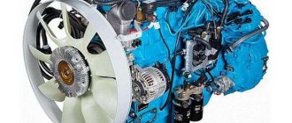
The standard unit for the D 240 L diesel engine is the PD-10UD starting engine. Other modifications of this engine for many assembly units are unified and are used in the starting systems of tractors of the YuMZ-6L, T-150, T-150K, DT-75 brands. The single-cylinder engine, which is popularly called “Puskach”, is located on the left side of the tractor and is attached to the rear plate of the diesel engine.
kinematic diagram of the tractor starting system with a starting motor
The starting system consists of three parts:
- Working cylinder with crank mechanism
- A distribution gearbox that provides drive to the ignition generator - magneto, speed controller of the starting engine and a separate transmission gearbox
- The starting engine transmission, which performs the function of transmitting the created torque directly to the tractor diesel flywheel.
Starting motor PD 10 UD assembled
Technical characteristics of PD-10 UD
- Power – 7.36 kW/10 hp. ̄
- Cylinder diameter 72 mm
- Stroke 85 mm
- Volume 0.346 l
- Compression ratio 7.3
- Maximum operating time under load is up to 10 minutes.
- Gear ratio of single-stage gearbox 16.8
- Type of electric starter used ST-362
Working cylinder and crank mechanism
The cylinder is attached with its lower part to the engine crankcase. The cast iron part with inlet, exhaust and purge windows is cast with external flanges for appropriate mounting of the carburetor and exhaust pipe, as well as a flange for connecting the water cooling cavities with pipes to the diesel system.
Launcher device PD 10
The engine head is mounted on the cylinder through a metal-asbestos gasket on four studs. The symmetrical arrangement of the head mounting holes allows it to be installed in any convenient position when connecting the supply flange to the diesel water jacket. In the head with a combustion chamber, a spark plug is installed in the central threaded hole. Additionally, the part is equipped with a decompression valve for purging the cylinder.
The engine crankcase consists of a pair of cast parts. This design allows the use of rolling bearings for two crankshaft bearings. The crankshaft consists of two axle shafts, two cheeks with counterweights, and a crank pin. Two rollers without cages and separators are installed in the lower one-piece head of the connecting rod, and a bronze bushing with holes for the passage of lubrication of the pin connecting the connecting rod to the piston is pressed into the upper one. To prevent rotation, the piston compression rings are locked with brass pins screwed into the landing groove. A flywheel is installed at the outer end of one axle shaft; the drive gear of the distribution gearbox is installed on the other. The end of the axle shaft with the gear rests on a ball bearing, which does not allow the shaft to move in the axial direction under the acting forces of the drive gears.
Cylinder of a two-stroke starting motor Crankshaft of the starting motor with connecting rod Head of the starting motor
The flywheel with the ring gear for the starting drive from the electric starter is fixed on the shaft with a key connection and is closed by an additional crankcase, into a special hole in which the starter is attached with two bolts. Part of the flywheel cover is removable for use with a cord starting drive.
The mechanism is lubricated with oil diluted in the gasoline supplying the engine in a ratio of 20:1. During operation, oil vapors and condensate are deposited on the parts of the unit, lubricating the rubbing surfaces.
Features of assembly and repair
The piston group of the working cylinder of the PD-10 starting unit includes two repair sizes:
| Dimensions | Industrial | Repair No. 1 | Repair No. 2 |
| Piston skirt diameter, mm | 71,82 (-0,03) | 72,57(-0,03) | 73,32(-0,03) |
| Cylinder diameter, mm | 72 (+0,03) | 72,75(+0,03) | 73,50(+0,03) |
- The connecting rod pins and mounting holes in the piston come in two sizes, marked with paint on the end of the pin and the piston boss. The smaller size is marked with white paint, the larger one with red paint.
- The pin with connecting rod is seated into the piston holes while it is hot when the piston is heated in oil to 100˚C.
- The piston is installed so that the arrow stamped on the spherical bottom of the part points towards the flywheel of the unit. This position prevents the joints of the compression rings from getting into the cylinder windows, preventing their breakage during operation.
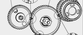
Distribution gearbox
In the composite front part of the crankcase there is a gearbox with distribution gears. From the drive gear 5 at the front end of the crankshaft, rotation is transmitted to the intermediate gear 1, which transmits torque to the starting engine transmission. At the same time, through the intermediate gear, drive is carried out through the corresponding magneto gears 4.6 and the engine regulator, which are mounted in the holes in the wall of the front part of the gearbox housing.
Starting motor distribution gearbox
For correct installation of the magneto with an ignition spark advance angle of 27˚, the intermediate gear of the gearbox is installed in compliance with mark K with mark K on the crankshaft gear and mark M with the mark of the same name on the magneto drive gear.
Carburetor power system
Mixture formation is carried out due to the vacuum created by the engine. The system includes a fuel tank, carburetor, and air filter.
Floatless carburetor K 06 starting engine
The PD-10 engine is equipped with a single-diffuse, floatless carburetor type 11.1107 brand K 06 with a horizontal mixing chamber. When the engine is not running, the fuel blocked by the valve does not flow into the supply channel. At start-up and during operation, the valve opens under the action of the diaphragm, which bends from the created vacuum in the mixing chamber. To enrich the mixture, when the engine starts, the diaphragm is forcibly bent by pressing the damper rod at the bottom of the device.
Carburetor device K 06
Speed controller
To limit the maximum crankshaft speed in accordance with the current loads, the engine is equipped with a centrifugal-type mechanical governor. The device is mounted on the front cover of the distribution gear housing and is driven by the corresponding gear. The principle of operation is the response of the centrifugal device of the regulator to the speed of rotation of the crankshaft of the starter.
The connected rod of the regulator 8 with the throttle control lever 3 of the carburetor 1 automatically regulates the supply of the fuel mixture and the maximum rotation speed. The sensor of the device is a sliding cone coupling 12, the axial movement of which is carried out as a result of increasing centrifugal force. The 15 balls diverging in the cone move the clutch and the ball stop 11 rotates the arm of the lever 9 connected to the carburetor flap.
Mechanical regulator of centrifugal type engine PD 10
During engine operation, the opening of the carburetor throttle corresponds to the load. When it decreases, the increasing centrifugal force moves the sensor balls and extends the sliding sleeve. The lever, overcoming the force of spring 5, closes the throttle, limiting the rotation speed in accordance with the reduced load.
Regulator setting
The rotation speed range is adjusted by changing the spring force that presses the lever to the ball stop of the governor sliding clutch using screw 7. As well as by changing the length of rod 3 connecting the governor to the throttle. To adjust the regulator, install a tachometer on the rear axle shaft of the crankshaft. Based on the technical characteristics and operating mode of the unit, the regulator setting should ensure engine operation within the following speed limits:
- Maximum under load no more than 3500 rpm
- Maximum idle 4200 rpm
- Minimum stable operation at 1300 rpm
Ignition system
The mixture in the combustion chamber is ignited by a spark plug generated by a single-spark magneto of the M124-B1 brand. The unit consists of a magnetic-electric generator, a breaker and an ignition coil.
Magneto of the starting engine ignition system
To install the ignition, turn out the spark plug and, using an inserted rod into the hole, turning the crankshaft, determine the position of the piston at TDC. To ensure an ignition advance of 27˚, lower the piston in the opposite direction to the working rotation by 5...6 mm. The magnetto is installed with the cover removed in the position of the generator shaft (with the coupling protrusion hole at the top) when the breaker contacts begin to break. This position corresponds to the moment of spark breakdown in the spark plug electrode gap. In this position, the grooves of the coupling half and the drive gears are connected. Ignition correction is carried out by radially changing the position of the magneto housing in the elliptical holes of the assembly mounting flange.
Magneto ignition device PD 10
For normal operation of the magneto, the gap in the contacts of the breaker must be within 0.25...0.35 mm, while maintaining parallelism of the planes. The gap in the spark plug electrodes is set within 0.6...0.75 mm.
Magneto contacts
How to set the ignition timing with your own hands
Setting the ignition correctly means that you need to find the desired ignition timing (IAF). The tuning is done at idle, although this is understandable, but suddenly someone decided to put the car on a jack and tune it at speed.
To adjust the ignition, you need to know that the optimal good engine crankshaft speed at idle is from 850 to 900 rpm. The ignition timing angle should be between -1 and +1 degrees. This is a degree relative to top dead center (TDC).
If a light bulb is used for adjustment, it is connected to the positive terminal on the ignition distributor (distributor), and the light bulb base is connected to ground. Let's look at the configuration options separately.
Strobe setting
- Start the engine, heat it to operating temperature and turn it off.
- Connect the strobe light to the car's network.
- Unscrew the nut securing the distributor cap - ignition breaker.
- Place the alarm sensor on the high-voltage wire of the first cylinder.
- If there is a vacuum corrector hose on the distributor, then it must be disconnected and plugged.
- Direct the strobe light onto the engine crankshaft pulley.
- Now start the engine and leave it idling.
- Now you need to turn the distributor body and fix it so that the mark on the crankshaft pulley coincides with the mark on the timing mechanism.
- If the marks match, tighten the nut.
How to set the ignition with a control light
- Rotate the engine crankshaft until the mark on its pulley coincides with the timing mark.
- In this case, the ignition distributor slider should be directed to the first cylinder.
- Now you need to loosen the distributor nut.
- One wire is connected to the core of the warning lamp (control) and to the ignition coil wire (bobbin).
- The second wire connects the ground and the light bulb base. The light should light up.
- After this, you need to turn on the ignition by turning the ignition key and turning the distributor body clockwise. When the distributor rotates, the light will go out in some position. In this position, tighten the distributor clamping nut.
Checking the fuel supply start angle
Adjusting the fuel supply advance angle is one of the ways to adjust the ignition on the MTZ on the fuel pump. The angle at which the fuel supply begins is responsible for the timeliness of combustion of the mixture. By adjusting the fuel supply advance angle to the injection pump, you can change the ignition delay time, the rate of pressure increase and the location of the combustion line relative to top dead center (TDC).
Typically, adjusting the ignition on the fuel injection pump means shifting fuel combustion closer to the beginning of the expansion cycle. But the adjustment must be controlled, since with a significant displacement problems will arise: towards the end of combustion, the pressure will drop and the temperature of the exhaust gases will increase. As a result, thermal energy losses will increase and diesel consumption will increase.
To check the fuel advance angle, proceed as follows:
- Set the fuel feed lever to the maximum flow position.
- Screw in the momentoscope instead of the tube on the first section of the fuel injection pump.
- Turn the crankshaft using a wrench until diesel fuel comes out of the glass tube of the momentoscope without air bubbles.
- Shake the tube to remove some of the fuel. Stop rotating the crankshaft when the level of diesel fuel in the glass tube begins to rise.
- Unscrew the installation bolt and insert its other end into the same hole until it stops against the flywheel.
- The installation bolt should line up with the hole in the flywheel - this means that the piston of the 1st cylinder is at the 26 degrees BTDC position. If this does not happen, you need to change the position of the splined flange in relation to the injection pump drive gear.