The SK-4 self-propelled grain harvester is equipped with two independent hydraulic systems: main and additional. The main one is intended for servicing the V-belt variator of the chassis speed, raising and lowering the header and reel and adjusting its rotation speed. The auxiliary hydraulic system only serves the power steering. In the latest production combines, the main hydraulic system is also used to drive the stacker mechanisms.
The threshing cylinder or rotor of a combine is driven by a hydraulic rotor motor. The rotary pump, driven by the internal combustion engine, supplies hydraulic fluid to the rotor motor to drive the rotor. A variable speed traction drive moves the combine across the field to harvest the crop. The control system varies the ground speed of the harvester based on the hydraulic fluid pressure supplied to the rotor hydraulic motor to maintain a substantially constant rate of feeding material through the threshing cylinder or rotor.
Tank 1 with an 18-element drain filter is common to both systems. The filter safety valve is adjusted to a pressure of 1.5 kg/cm2. Pump 2 of the main hydraulic system, brand NSh-32, right-hand rotation, with a nominal speed of 1480 per minute. Pump 3 of the power steering system - NSh-10, right-hand rotation with a nominal speed of 1700 per minute. Both pumps are driven by the engine timing gears. Pump 1 of the NSh-10 brand (Fig. 2) is fixed in spacer 2 and is driven into rotation by a non-disengaging cam clutch 3. Pump 4 of the NSh-32 brand is driven by clutch 6, activated by fork 5 only when the engine is not running.
Description of the invention for the patent
The control system may be an electronic system that senses hydraulic fluid pressure on the upstream side of the rotor hydraulic motor and modulates ground speed to maintain the measured hydraulic fluid pressure substantially constant.
The control system may also include a pressure control valve that modifies the ground speed to maintain hydraulic pressure at the inlet to the permanent rotor motor. A combine containing a frame; a harvesting mechanism mounted on the front of the frame, a threshing cylinder and a concave unit mounted on the frame, which receives cultivation material from the harvesting mechanism and threshes the material for sowing; a hydraulic cylinder drive motor that rotates the threshing cylinder; a variable speed traction drive that moves the harvester across the field; and a controller connected to the variable speed traction drive and the cylinder drive hydraulic motor, which senses the pressure of hydraulic fluid driving the cylinder drive hydraulic motor, compares the measured pressure with the selected pressure set point, and modifies the variable speed traction drive to control the material feed rate. for seeding going into the threshing cylinder and concave assembly.
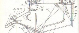
Distribution valve 11 (see Fig. 1) is used to control plunger power cylinders 5, b and 7 of single-acting action. The diameter of cylinder 5 is 60 mm and the stroke of the plunger is 360 mm. A valve 4 is installed in the cylinder line 5, which closes the cylinder cavity during long journeys of the combine with the header raised. The device of valve 12 for controlling the power cylinder 13 of the variator of the combine chassis is the same as that of valve 11, the difference is that its plug only makes a rotary movement. The valve is connected to the pump discharge line behind the safety valve 14 and the accumulator control spool 15. The valve plug can be in three positions: “neutral”, “increase speed” and “decrease speed”. In the “neutral” position, both cavities of the power cylinder 13 are locked, and the oil from the pump passes through the cavities of the valve 12, and then through the distribution valve 11 is drained into the tank. To increase the speed, the valve handle is turned to the left, while oil is supplied to the rod cavity of the power cylinder 13. To reduce the speed, the valve handle is turned to the right, as a result of which oil is supplied to the piston cavity of the cylinder. Cylinder 13 piston, double-acting, piston diameter 40 mm, stroke - 153 mm. When the piston moves in one direction or another, the block of variator pulleys lowers and rises accordingly. As the piston moves downwards, the pulley block lowers and the V-belt enters deep into the block, which leads to an increase in the rotation speed of its pulleys. When the piston extends, the block rises, and the belt moves to the periphery of the pulleys, and their rotation slows down. To improve the process of stack formation and facilitate the work of the combine operator, a mechanism for automatically closing the bottom and valve (rear grill) of the stacker has been introduced on combines. This mechanism consists of sensors, which are hinged strips 20, connected by a system of rods 17 and levers with a spool 15, power cylinders 18 and a hand lever 16. In Figure 1, the bottom 22 and the stacker valve 21 are shown closed. In this position, the cylinder rods 18 are extended to the end, and the spool 15 is in the extreme right position. Oil from pump 2 enters the spool body and then, as shown by the arrow, flows freely through valve body 11 into the tank. The cavities of the power cylinders are also connected to the tank by spool 15. When unloading the hay, the spool remains in the same position, and the plungers of cylinders 18 move down, displacing oil into the tank. Throttle washers are installed at the entrance to the spool, which are discarded when drained and do not prevent the oil from leaving the cylinders. When pumping, the washers are pressed against the distributor body and, limiting the oil supply, contribute to the smooth closing of the valve and bottom. The mop, coming off the bottom, deflects the sensor bars 20 upward. After unloading the hay, the slats fall and, using a system of rods 17 and levers, move the spool to the left. In this case, the drain channels of the spool are blocked, and the pump discharge line is connected to the cavity of the power cylinders 18. The plungers, moving upward, close the valve and the bottom. As soon as they close, the feedback mechanism 19 will operate, which will bring the spool to the drain position shown in the figure. The hydraulic drive of the stacker uses the same cylinders as for lifting the reel. The hydraulic system of the SSh-75 self-propelled harvesting and transport chassis is similar to the hydraulic system of the SK-4 self-propelled combine. Two pumps NSh-32 and NSh-10 with a common drive are installed on the engine.
The combine harvester of claim 1, wherein the harvester comprises an engine and a cylinder drive hydraulic pump driven by the engine and connected to the cylinder drive hydraulic motor by a supply pipe that supplies hydraulic fluid under pressure to the cylinder drive hydraulic motor.
Adjusting the main hydraulic system units
The harvester of claim 1, wherein the variable speed traction drive includes a traction drive hydraulic motor that provides torque to move the harvester across a field, and the speed of the traction drive hydraulic motor is varied to vary the rate at which material is supplied for planting.
Master the disassembly, assembly and adjustment of the oil tank, gear pump NSh-32U, sectional distributor, air intake hydraulic cylinder and grain bin vibrator.
Consider the design features of the main hydraulic system units on the SKD-5 and SK-5, SK-6 combines.
Workplace equipment
. Training combines SK-5 or SK-6 with complete hydraulic systems; valve spring remover with split washer; caliper ShTs-P-0.1-200; spanners 27X30, 22X27, 22X24, 17X19, 12X14; mechanic's hammer 800 g; combination pliers 200 mm; screwdriver L200X 1.0 mm; calibration key.
The combination harvester of claim 5, wherein the variable speed traction drive includes a traction drive motor and a traction drive pump connected to each other by a traction drive supply line and a traction drive return line that forms a closed loop hydraulic traction drive system.
Disassembly, assembly and adjustment of components of the main hydraulic system
A self-propelled harvester comprising a frame; many wheels supporting the frame; at least two driven wheels mounted on the frame to move the frame; a harvesting mechanism mounted on the front of the frame for transporting the cultivation material into the separator body; threshing and separating rotor, with the ability to rotate on a frame inside the separator housing; concave, mounted on a frame that interacts with the thresher and the separating rotor to grind the grain; a separating grid mounted on a frame, which interacts with the thresher and the separating rotor to separate the grain from the threshed material; a cleaning unit mounted on a frame inside the separator casing; an internal combustion engine mounted on a frame to drive the combine; rotary hydraulic motor that controls the threshing and separating rotor; a rotary hydraulic pump driven by an internal combustion engine and connected to a rotor hydraulic motor to supply pressurized hydraulic fluid to the rotor hydraulic motor; hydraulic traction drive motor driving the driven wheels; a traction drive hydraulic pump driven by the internal combustion engine and connected to the traction drive hydraulic motor to supply pressurized hydraulic fluid to the traction drive hydraulic motor; a pressure sensor for measuring the pressure of hydraulic fluid entering the rotor hydraulic motor; an adjusting screw that changes the speed of the traction drive hydraulic motor; an electronic controller connected to a pressure transducer and an incline controller that compares the pressure signal from the pressure transducer to an adjustable pressure setpoint and sends signals to the incline plate controller as required to adjust the speed of the traction drive to maintain a substantially constant material feed rate for sowing through the threshing and separating rotor.
Work sequence
. Repeat the design of the main hydraulic system, designed to control the same working bodies as on the SKD-5 combine and, in addition, ensure cleaning of the radiator air intake mesh, unloading of loose grain from bins with vibrators, tipping the trailed trolley when working with a straw chopper, and on combines "Niva" - control of the movement of the conveyor frame of the ZhNS-6-12 windrower.
Operation of the steering wheel hydraulic booster
A self-propelled harvester comprising a frame;
many wheels supporting the frame; at least two driven wheels mounted on the frame to move the frame; a harvesting mechanism mounted on the front of the frame for transporting the cultivation material into the separator body; threshing cylinder with the possibility of rotation on the frame; concave, mounted on a frame that interacts with the threshing cylinder to fill the grain; an internal combustion engine mounted on a frame to drive the combine; a threshing cylinder hydraulic motor that controls the threshing cylinder; a source of hydraulic fluid connected to the hydraulic motor of the threshing cylinder; hydraulic traction drive motor driving the driven wheels; a traction drive hydraulic pump driven by an internal combustion engine and connected to the traction drive hydraulic motor to supply hydraulic fluid under pressure to the traction drive hydraulic motor, a traction pump inclined plate installed in the traction drive hydraulic pump to control the flow of hydraulic fluid to the traction hydraulic motor drive; a traction pump clutch control valve connected to a traction pump hydraulic pump that controls the position of the traction pump inclined plate; and a feed rate control valve connected to a hydraulic fluid inlet of the hydraulic motor of the threshing cylinder, a source of hydraulic fluid under pressure and in hydraulic communication with a control fluid inlet in the pump control valve of the oscillating pump, and wherein the feed rate control valve controls the flow of hydraulic fluid through the control input fluid to control the feed rate of material to trim material through the threshing cylinder and concave mold. Find the locations of the hydraulic units on the combines: oil tank 6 (Fig. 86), gear pump 7, safety valve 9 and accumulator spool 10.
Inspect the sectional distributor 4 and the placement of pipelines running from the distributor to the front part of the combine to cylinders 1 for raising the reel, cylinders 2 of the header and to the variator of the reel speed 17. The pipelines to the cylinder 13 of the variator of the chassis and to cylinder 5 of the air intake are routed to the right side of the combine. Pipelines are also laid from the distributor to the vibrators 3 of the hopper and to the cylinders 11 of the stacker.
A method for controlling the material feed rate of a combine harvester for controlling the speed at which cultivation material is fed to a threshing cylinder, and a harvester threshing concave material containing. Selection of the set pressure corresponding to the torque load on the threshing cylinder.
Measuring the pressure of the hydraulic fluid entering the inlet of the hydraulic motor of the threshing cylinder drive. Comparison of the measured hydraulic fluid pressure entering the cylinder drive hydraulic motor inlet with the selected pressure setpoint.
Considering the installation diagram of the main hydraulic system, repeat the principle of its operation, which is as follows: a large 7 gear pump NSh-32U (see Fig. 86) sucks oil from the oil tank 6, common to all hydraulic systems, and pumps it when the safety valve 9 is not working through accumulator spool 10 to distributor 4.
Increasing the speed of the combine when the measured pressure of the hydraulic fluid entering the inlet of the threshing cylinder drive hydraulic motor is less than the selected set pressure by more than a certain amount.
Reducing the speed of the soil movement of the combine when the measured pressure of the hydraulic fluid entering the inlet of the hydraulic motor of the threshing cylinder drive is greater than the selected set pressure by more than a certain amount; and adjusting the set pressure when the feed rate needs to be changed.
When the distributor spools are in the neutral position, oil pressure opens the bypass valve, and the oil goes through the outer drain channels of the distributor through the pipeline to be drained, passing through the oil tank filter.
When one of the distributor spools is moved from the neutral (middle) position to the working position, the front drain channel is closed and the oil is directed to the switched-on consumer.
Regulating the material feed speed of the combine harvester according to claim 21, including: selecting the maximum soil speed of the harvester, which is not exceeded when the measured pressure of the hydraulic fluid entering the inlet of the threshing cylinder drive motor is less than the selected set pressure.
This invention relates to combine harvesters and, more particularly, to a control system that controls ground speed to maintain a constant load on the threshing rotor. The grain threshing, separating and cleaning assemblies of the combine operate at maximum efficiency only if there is a constant flow rate of feed material. Changing the grain feed rate or the feed rate of crops other than grain affects the operation of the threshing, separating and cleaning assemblies.
Find on combine harvesters the mounting points for single-acting plunger hydraulic cylinders, which lift the reel, change the speed of its rotation, lift the header and the bottom of the stacker. A special feature of these hydraulic cylinders is that they reverse under the influence of the weight of the working element or spring.
Consider the design of plunger hydraulic cylinders, which consist of a plunger and a housing. The housing has seals in the form of rubber rings and a wiper lip. The fitting connects the hydraulic cylinder to the pipeline, and the locking ring limits the exit of the plunger from the housing.
Standard adjustments found on harvesting machines allow different crops to be placed and harvested in different crop and weather conditions. However, these adjustments require time and skill. Changing the amount of material flowing through the combine can significantly change the efficiency of a harvest operation, even if weather and crop conditions remain the same.
Reducing the amount of seed passing through the threshing cylinder or rotor and concave can result in a significant increase in the amount of cracked grain. The cracked grain is blown out of the combine and onto the ground using the cleaning system's fan.
Find places to install double-acting hydraulic cylinders on combines, which clean the radiator air intake meshes, rotate the rear wheels of the combine, raise and lower the block of pulleys of the chassis variator for steplessly changing the speed of the machine.
Repeat the general structure of piston hydraulic cylinders using the example of a hydraulic cylinder for a variator, which consists of a sleeve within which a piston with sealing rubber rings moves. The sleeve is attached to the right side of the thresher. The rod passes through the cylinder head, which also has O-rings and a wiper seal. The piston rod is attached to the fork lever of the pulley block.
Increasing the amount of seed passing through the harvester can overload the cleaning system, creating a mat of seed material on the shredder screen, and most of the crushed grain will end up on the ground rather than in the grain tank. Increasing the amount of seed passing through the harvester can also overload the separating units and cause grain loss.
Combine harvesters are designed to operate at maximum threshing unit capacity, separation of assembly and cleaning units, and power source at any given time. To do this, the capacitance of each of the assemblies and the power supply must be balanced with each other. Due to changes in crop and weather conditions, it is impossible to achieve a perfect balance between threshing, separating and cleaning units and the energy source. In practice, operators typically adjust the threshing, separating and cleaning assemblies to feed crop material feed rates that provide sufficient power to advance the combine with current field conditions and to empty the grain tank.
On combine harvesters, find the installation location for shut-off valve 16 (see Fig. 86), which is designed to lock the oil in the plunger hydraulic cylinders of the header during transport crossings. At the same time, the valve is a tee that branches the fluid flow from one pipeline into two hydraulic cylinders.
After lifting the header, the spindle is screwed all the way into the conical seat of the valve body. Rubber ring seals eliminate oil leaks.
Replacing the cylinder cuffs of the counter-drive variator Niva SK 5
Repair of the hydraulic cylinder of the drum variator with the Yenisei combineRead more
Reworking the variator of the NIVA-EFFECT combine harvesterMore details
Repair of a running variator on a combine harvesterRead more
Repair of the running variator Niva SK-5 on your ownRead more
Repair of hydraulic cylinder variator drum small and large Niva sk5 GA-76010, GA-76020More
From the Adiron™ Company Rem-kt Hydro-dra Variator Drum Niva SK-5 GA-76010. GA-76030More details
Main hydraulic system of the SKD-5 combine
Purpose and content of the work . To consolidate knowledge of the design of units of the main hydraulic system. Find the attachment points of the main hydraulic system components on the combine and examine how the hydraulic connection between them is carried out.
Master the disassembly, assembly and adjustment of components of the oil tank, safety valve, variator control valve, distributor valve, hydraulic cylinder of the variator, reel lifting cylinder.
Workplace equipment . Training combine SKD-5 with a complete hydraulic system; spanners 8X10, 12X14, 17X 19, 22X X24, 27X30, 32X36; special key for adjusting the oil tank safety valve; screwdriver A 250X1.4; wrench for the jack (SMD 1-4921); metalworking bits 3 and 6 mm; mechanic's hammer 500 g; combination pliers, ruler 300 mm; caliper ShTs-P-0.1-200; vice P-120; wooden pin with a diameter of 7.5 mm, a length of 100 mm to control the coincidence of the housing holes and the spool valves.
Sequence of work execution . Repeat the design of the main hydraulic system, which serves to raise and lower the header and reel, change the speed of rotation of the reel and the speed of movement of the combine, and is also intended to close the stacker.
Find on the SKD-5 combine (Fig. 73) the location of the hydraulic units of the main hydraulic system. Examine the laid oil lines and repeat the principle of operation of the main hydraulic system, which is as follows.
Gear pump 6 NSh-32E sucks oil from the oil tank 11 and pumps it, with the safety valve 27 inoperative, through the accumulator spool 30 into the control valve 22 of the chassis variator. This tap is connected in series with distributor tap 19.
When both valves are in the neutral position, the channels in the valve bodies through which oil is supplied to the hydraulic cylinders are closed. With this position of the valves, the oil leaves the distributor valve through the oil line 20 and passes through the filter 12 into the oil tank 11.
By turning the handle of the control valve, they change its position in the housing and thereby direct oil under pressure into the upper or lower cavity of the hydraulic cylinder 25. The oil presses on the piston of the hydraulic cylinder, which through the rod lowers or raises the fork 26 of the variator pulley block, accordingly increasing or decreasing the speed of the combine.
When lifting and turning the handle of the distributor crane 19, oil enters one of three plunger cylinders: hydraulic cylinder 17 of the reel speed variator, reel lifting cylinders 13 or plunger lifting cylinders of the header 9.
Find and examine the installation locations of the single-acting plunger hydraulic cylinders and the double-acting piston hydraulic cylinder of the chassis variator on the combine. Repeat their device.
The variator hydraulic cylinder of the double-acting piston chassis (Fig. 74) is designed to raise and lower the fork of the variator pulley block.
The hydraulic cylinder consists of a sleeve 8 with a blind head 1 welded into it and fittings 7 and 10 with throttle holes with a diameter of 2.5 mm. The front head 11 is screwed into the sleeve on a thread and has a hex key.
A cast iron piston with a diameter of 40 mm has two rubber sealing rings 4 installed in the grooves. The piston is secured to the rod 9 with a cotter nut 2. The exit of the rod from the front head is sealed with two rubber rings 13 and a wiper lip 14. A fork 16 is screwed onto the inner end of the rod, which is secured with a nut 15.
The plunger hydraulic cylinder for lifting the header (Fig. 75) consists of a plunger 6, a rear blind head 1 with a fitting 3 screwed into it, and a front head 7 connected to the plunger 6 with a thread. The hollow plunger consists of a pipe 12, a head 11 and a bottom 13, into the groove of which a thrust ring 4 is inserted, limiting the exit of the plunger. The seals are provided by rubber rings 8, 9 and a wiper lip 10.
By turning the handle of the control valve, they change its position in the housing and thereby direct oil under pressure into the upper or lower cavity of the hydraulic cylinder 25. The oil presses on the piston of the hydraulic cylinder, which through the rod lowers or raises the fork 26 of the variator pulley block, accordingly increasing or decreasing the speed of the combine.
When lifting and turning the handle of the distributor crane 19, oil enters one of three plunger cylinders: hydraulic cylinder 17 of the reel speed variator, reel lifting cylinders 13 or plunger lifting cylinders of the header 9.
Find and examine the installation locations of the single-acting plunger hydraulic cylinders and the double-acting piston hydraulic cylinder of the chassis variator on the combine. >Replicate their device. The variator hydraulic cylinder of the double-acting piston chassis (Fig. 74) is designed to raise and lower the fork of the variator pulley block.
The hydraulic cylinder consists of a sleeve 8 with a blind head 1 welded into it and fittings 7 and 10 with throttle holes with a diameter of 2.5 mm. The front head 11 is screwed into the sleeve on a thread and has a hex key.
The cleaning system of combines is designed to separate grain from a small heap, which is supplied to the shaking board from the threshing apparatus, straw walker and post-threshing device. The grain cleaning system of the KZS-9-1 combine includes: shaking board 1 (Fig.) with finger screen 6, upper and lower sieve frames, upper sieve extension, fan, threshing device, suspensions and drive mechanisms.
Shaking board - (Transport board) has a stepped surface on which longitudinal combs are fixed. They divide the board into five tracks, which keep the pile from moving to one side when the combine is tilted transversely. The front part of the board is suspended from the thresher frame by two hangers. Seals (strips made of rubberized material) are attached to the left and right sides of the transport board. They fit tightly to the sides of the thresher body. At the end of the transport board there is a grid of stamped steel fingers attached.
The upper sieve frame is located behind the transport board. The front part of the mill is hingedly connected to the body of the board, and the rear part is attached to two upper hangers. The upper sieve is fixed in the upper sieve state.
The lower sieve looks like a box with a pallet. The front part of this mill is suspended from the double-arm lever of the drive mechanism, and the rear part is connected to the thresher frame by two lower suspensions.
The transport board and sieve frames are driven into oscillatory motion by connecting rods connected to the double-armed levers of the drive mechanism.
The louver screen consists of a frame on which metal strips with teeth (blinds) are placed. The elbow of the blind axis fits into the cutout of the rail to which the nut is attached. The nut screw is connected to the regulator. The upper sieve separates larger parts of the heap and has larger louvres.
The sieve frame of the lower sieve 14 oscillates in the opposite direction and with a smaller amplitude than the transport board and the upper sieve frame.
At the end of the upper sieve 11 there is a hinged extension 12 of the louver type.
The angle of the blinds is adjusted using a lever.
Fan 17 Cleaning - centrifugal type, six blades. There are dividers installed in the fan neck to direct the air flow to the cleaning sieves. The fan is driven by a V-belt variator from the counter-drive pulley.
The principle of operation of a grain cleaner . The small heap that arrives on the transport board is distributed under the influence of vibrations. Grain and heavy impurities move down; and light and large straw ones occupy the top position. Due to oscillatory movements, a small heap enters the finger grid, on which large impurities are retained, and the small fraction falls onto the front part of the upper sieve 11. The large fraction rises from the finger grid and falls into the middle of the sieve. The bulk of the grain and small impurities are sifted through the holes of the upper and lower sieves. Fan 19 supplies air flow to the sieves to loosen the heap and move light particles to the floor filler. The cleaned grain falls on; the pitched board 15 of the sieve mill, and from there into the grain auger. The extension of the upper sieve retains the unthreshed spikelets, which pass through the blinds and fall into the chute of the spikelet auger 16. From the auger, the spikelets are fed by an elevator to the pre-threshing device, and after threshing, the heap is sent by the auger to the transport cleaning board.
Rice. 15. Schemes of air-sieve cleaners for combines:
A - KZS - 9-1; b - ; V - ;
1 and 20 - transport boards; 2 - comb; 3 — connecting rod; 4 - apron;
5 — grain elevator; 6 — finger grille; 7 — pre-threshing device; 8 — grating surface; 9 – finishing drum;
10 — spikelet elevator; 11 and 22 - upper sieves; 12 — extension of the upper sieve; 13 – longitudinal blinds; 14 and 23 - lower sieves; 15 - pitched board; 16 — grain auger; 17 — grain auger; 18 — dividers; 19 — fan; 21 — additional transport board; 24 - additional sieve
Basic adjustments. The gap between the blinds of the upper and lower sieves is adjusted within 0-17 mm by a lever mechanism, between the blinds of the extension by a lever within 0-20 mm, and between the longitudinal blinds by moving the latch. The angle of inclination of the extension is set by moving it to one of two positions. The fan rotor speed is controlled by a variator within the range of 355-916 rpm.
In order to intensify the cleaning of small heaps, foreign combine designs install an additional transport board 21 or an additional third sieve between the transport board and the upper sieve of the grain cleaning machine. For some cleaning operations, an additional third sieve is secured to the rear of the transport board. In addition, more powerful turbine fans and an increased area of their screens up to 6 m2 have been used in the grain cleaning systems of combine harvesters (Fig. 16-17).
• Fig. 16. Cleaning system on John Deere WTS combines. Fan diameter increased from 450 mm to 500 mm
Fig. 17. New cleaning of the LEXION 570 Jet Stream combine with a 6-flow turbine in a 1420 mm housing
Disassembly and assembly of main hydraulic system units
Disassemble the oil tank:
- Unscrew the bolts and remove the tank cover 2 together with the rubber gasket 1 (Fig. 76).
- Remove retaining ring 3, drain cup 24 along with filter elements 25 and safety valve 15.
- Remove the safety valve by unscrewing the nut 27. Measure the distance from the end of the valve 15 to the lock nut 16. During assembly, this dimension should be maintained so as not to violate the set valve response pressure of 1.5 kgf/s.m 2 (147.09-103 N/ m2).
- Remove gasket 23 and filter elements 25 from the filter tube.
- Unscrew lock nut 16 with nut 17 from valve body 15. Remove spring 18, crosses 19 and 20, and bypass valve ball 21.
- Remove the pressure bar, remove breather glass 8 from the tank and disassemble it.
Check the integrity of the gaskets and reassemble the oil tank in the reverse order of disassembly. To avoid damaging the mesh elements, do not tighten nut 27 too tightly.
Disassemble the safety valve:
- Disconnect the valve from the pipelines and remove from the combine.
- Measure the distance from the end of screw 1 (Fig. 77) to the end of housing 3 and write down the number.
- Loosen locknut 2 and unscrew adjusting screw 1 from the valve body.
- Remove guide 6, spring 7, plate 8 and ball 9 from the body.
Check the ball for ellipse, check the integrity of seat 10 and assemble the valve in the reverse order of disassembly.
To maintain the previous valve adjustment to the response pressure of 50 kgf/cm1 (5 MPa), screw 1 must be screwed in so that the length of its protruding part remains the same as before disassembly.
Disassemble the variator control valve:
- Disconnect the pipelines from the fittings of the valve body, and the switching mechanism from the valve rod, having previously unscrewed bolt 10 and removed cotter pin 5 (Fig. 78). Remove the control valve from the combine.
- Unscrew bolts 14 securing covers 3 and 10 (Fig. 79) and remove them. Remove tap 9 from housing 7.
Pay attention to the fact that fittings 5 and 8 (see Fig. 79) communicate with the housing through throttle holes in order to ensure a smooth change in the speed of the combine.
Check whether the sealing rings are damaged, whether the hole in the shaft 4 for the locking bolt 10 is worn (see Fig. 78), whether the stand 7 is bent. Assemble the control valve in the reverse order of disassembly and install it on the combine.
Disassemble the distributor valve:
- Disconnect the pipelines from the fittings of the distributor valve. Unscrew bolt 15 (Fig. 80), knock out pin 19, unscrew three nuts 21 and remove the distributor from the driver’s platform.
- Remove the upper 1 and lower 9 covers of the distributor housing 5, unscrewing the bolts 10, and remove the valve 6. Remove the rubber rings 3, 4 and 8 from the housing covers (Fig. 81).
- Unscrew fittings 11, 12, 13 and 14 from the housing. Pay attention to the fact that fittings 12 and 14 communicate with the body through throttle holes with a diameter of 2.5 mm.
Disassemble the valve control mechanism:
- Remove the cotter pins from axles 8 and 11 (see Fig. 80). Knock out the mounting axes of handle 9 on shaft 13 and on bar 2. Disconnect handle 9 from shaft 13.
- Unscrew the screw and remove flange 7 from shaft 13. Separate race 6 from the flange, remove spring 5 with ball 4 from the hole in the flange.
Reassemble the distributor valve together with the switching mechanism in the reverse order and install it on the combine.
Disassemble the reel lifting plunger hydraulic cylinder:
- Secure the cylinder with head 7 (see Fig. 75) in a vice and unscrew the head with a knob. Remove the wiper seal 10 and rubber rings 8 and 9 from the head (see Fig. 75).
- Remove plunger 6 from pipe 5 and remove thrust ring 4 from it.
- Unscrew fitting 3 from cover 1 of the hydraulic cylinder. Assemble the hydraulic cylinder in the reverse order of disassembly.
Disassemble the piston hydraulic cylinder of the chassis variator:
- Disconnect the hoses from the cylinder fittings, and the rod fork from the pulley block lever. Remove the hydraulic cylinder from the combine, holding the pulley block with a pry bar.
- Secure the hydraulic cylinder in a vice and turn out the front head 11. Pull out rod 9 with piston 6 (see Fig. 74).
- Unsplit the piston nut and remove it from the rod 9.
- Loosen nut 15 and unscrew plug 16 from the rod.
Checking and adjusting components of the main hydraulic system
Check the correct installation relative to the body of the variator control valve:
- Disconnect the discharge pipeline from fitting 13 (see Fig. 79).
- Check the alignment of the oval groove of the faucet with the hole in the housing visually or using a wooden pin with a diameter of 7.5 mm.
- If the housing hole does not coincide with the oval groove of the tap, then you should check the fit of the locking bolt 10 (see Fig. 78) or straighten the stand 7.
During operation, it should be remembered that oil enters the hydraulic cylinder of the chassis variator only in the extreme positions of the shift mechanism handle. Holding the handle in intermediate positions leads to oil bypass through the safety valve, which causes overload of the pump and heating of the oil.
Check the installation of the distributor valve:
- Set the faucet handle to the middle position.
- Unscrew the middle fitting 13 to the header cylinders (see Fig. 81).
- Rotating coupling 18, install the tap so that a wooden probe with a diameter of 7.5 mm passes through an oblong hole into the longitudinal groove of the tap (see Fig. 80).
- Select the number of adjusting shims so that the distance from the platform to the lower flange is 50.5 ± 0.1 mm.
- Determine the holes that coincide on the flanges and install bolt 15 in them (see Fig. 80) with adjusting shims 17, nut and spring washer. If the bolts are lost, you can quickly install the crane in the field using the factory marks on couplings 16 and 18.
The serviceability of the plunger hydraulic cylinders of the header, the valve and the distributor valve on a working combine is checked in this way:
- Start the engine and raise and lower the header several times.
- Raise the header to its highest position and place the control handle of the distributor crane in the neutral position.
- Measure the distance from the end of the front cylinder head of the header to the end of the plunger.
- This measurement is repeated after 30 minutes of driving the combine with the header raised. Sagging of the plungers by more than 50 mm indicates the presence of unacceptably large gaps in the distributor valve and leaking seals in the cylinders and in the shut-off valve.
The tightness of the shut-off valve is checked in this way:
- Raise the header to the highest position.
- Screw the shut-off valve spindle all the way.
- Measure the distance from the end of the front head to the end of the cylinder plunger.
- Disconnect the oil line going to the distributor valve from the valve.
- Check for leaks through the middle valve fitting.
If there are oil leaks, replace the valve. If there are no leaks, it is necessary to check the seals of the header hydraulic cylinders. To check you need :
- Raise the header and close the shut-off valve with the oil lines connected to it.
- After driving the combine for 30 minutes, measure the distance from the end of the front cylinder head to the end of the plungers.
If the shrinkage exceeds 5-6 mm, then the cylinder seals must be replaced. If the shut-off valve and cylinders are tight and the shrinkage exceeds 45 mm, then the distributor valve must be replaced.
Check the response pressure of the safety valve. In field conditions, the valve response pressure can be set by the time the header is raised from the lowest to the highest position. If the header, without its shoes touching the soil, rises to the top position in more than 5 seconds, then you need to increase the compression of the valve spring by releasing lock nut 2 and rotating screw 1 clockwise one or two turns (see Fig. 77). Then lower the header and raise it again, noting the time of raising, for example, on the central second hand of a wristwatch or stopwatch. The experiment is repeated several times until the time required to raise the header is 4-5 seconds. The set pressure should not significantly increase the reel's lifting speed, otherwise it will be difficult to set it to intermediate positions.
More precisely, the valve response pressure can be set using instruments directly on the combine. It should be equal to 50 kgf/cm (5 MPa).
Adjust the stroke of the hydraulic cylinder rod of the chassis variator . To eliminate overtension of the chassis variator belts and regulate their movement along the pulleys, the stroke of the hydraulic cylinder rod is limited by stops. The position of the stops is adjusted as follows :
- Loosen the bolts securing the clamps to the guide.
- Start the engine. Using the speed variator distributor, set the pulley block to its highest position. In this case, the upper belt should reach the outer diameter of the pulley, and the lower belt should touch the inner diameter of the pulley with its lower edge.
- Turn off the engine. Place the lower clamp as far as it will go against the stopper and lightly tighten the bolt.
- Start the engine and move the pulley block to the down position.
- Stop the engine, install the upper clamp and tighten its bolt.
- Start the engine and set the pulley block to the middle position.
- Turn off the engine and move the top clamp down and the bottom clamp up by 1-1.5 mm. Tighten the clamp bolts fully.
Adjustment and repair of combine harvesters SK-5 "NIVA", SK-6 "KOLOS" AND SKD-5 "SIBIRYAK"
Maintenance of grain harvesters during operation involves timely completion of shift, periodic and seasonal maintenance operations, as well as compliance with labor safety and fire safety regulations.
They clean the engine, the radiator air intake mesh, the air cleaner intake mesh, the cutting device, the deck, the working surfaces of the straw walker, the screening board, the cleaning sieves, and the stone catcher from dust and dirt. Check the condition and reliability of fastening of the air intake, engine suction pipes, connecting cheeks of the cutting device blade, header auger, reel, header balancing mechanism, gauge shoes, V-belt and chain drives, safety clutches, straw walker bearings.
Check for oil, water and fuel leaks, the water level in the radiator, the oil level in the engine crankcase, in the fuel pump housing and in the regulator housing.
According to the diagrams (Fig. 115 and 116) and the lubrication table, lubricate the points (frequency 10 operating hours).
Rice. 115. Lubrication diagram for the Niva combine (left side).
Rice. 116. Lubrication diagram for the Niva combine (right side).
While the combine is operating, monitor the oil pressure, water and oil temperature, ammeter and tachometer readings, the color of the exhaust gases, light and sound alarms, as well as the operation of the entire machine.
On the follower reel, cast iron bearing 17 (Fig. 68) of the left trunnion is lubricated with universal grease.
First maintenance after 60 operating hours (TO-1) of Niva, Kolos, Sibiryak combines. Perform shift maintenance operations, then wash the air cleaner cassettes and reflector and moisten them in oil.
Tighten the air cleaner fastenings of the engine suction pipes. Drain the sediment from the fuel coarse filter housing.
Check and, if necessary, adjust the tension of the fan and generator belts.
Lubricate the engine clutch release bearing. Check the battery fastenings and the electrolyte level in them. Clean oxidized terminals and passage tips. Lubricate their non-contact parts with technical petroleum jelly or universal grease and clean the ventilation holes in the plugs of the elements.
Check the oil level and add it to the axle housing of the drive wheels, the drum gearbox (if there is one in the drive) and to the hydraulic tank of the hydraulic system.
Check and adjust: the parallelism of the auger and the position of the auger fingers relative to the bottom of the header body, the tension of the inclined conveyor chains, the tension of V-belt and chain drives, the operation of the brake system and clutch.
Check the air pressure in the tires of the drive and steering wheels and, if necessary, pump them up.
According to the diagrams (Fig. 115 and 116) and the lubrication table, the points are lubricated (frequency 10 and 60 operating hours).
Second maintenance after 240 operating hours (TO-2) of Niva, Kolos, Sibiryak combines . Perform shift maintenance and 60-hour maintenance operations and additionally perform the following operations: replace the oil in the engine crankcase and fuel pump;
clean the centrifuge; wash the turbocharger oil filter; wash the first stage of the fine fuel filter; lubricate the front bearing of the engine clutch shaft; Lubricate the water pump bearing. Remove and disassemble the air cleaner. Carefully wipe the air cleaner housing, especially the inside of the cyclones.
Clean and rinse the settling filter, breather (breather is a device through which the container communicates with the atmosphere to maintain equal pressure) of the engine, the cap and filter of the filler neck of the main engine fuel tank, the settling filter of the starting engine tank, the float chamber and the fuel supply fitting of the starting carburetor engine, filter and breather of the hydraulic system.
Check the condition of the electrical wiring (if necessary, isolate damaged areas), the condition of the generator, starter and starter contacts, the density of the electrolyte and determine the degree of discharge of the battery (if necessary, recharge or replace it with a charged battery).
Check and adjust the gaps between valves and rocker arms, spark plug electrodes and magneto breaker contacts, carburetor, engine clutch, clutch of the starting engine transmission mechanism, gear shift mechanism, steering.
Replace the oil in the drive wheel axle housing and the drum gearbox (if the drive has one).
Maintenance during storage of Niva, Kolos, Sibiryak combines After the completion of the harvesting season, clean the combine and its units from dust, dirt and crop residues;
inspect the combine and assess its technical condition. If the combine does not need repairs, then all maintenance operations during storage are carried out in accordance with GOST 7751-71. Eliminate technical faults discovered during inspection.
Electrical equipment units, fuel pumps and injectors are checked and adjusted in a repair shop before they are preserved.
Before harvesting begins, remove the combine from storage, having completed all operations for removing machines from storage, and perform regular maintenance operations.
Next is the lubrication of combines. Subsequence.