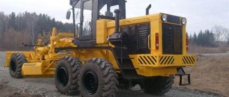
Don-1500
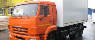
- Soviet grain harvester. The Rostselmash enterprise has been producing this combine since 1986 for twenty years. In 2006, Rostselmash switched to newer models (Vector and Acros). At one time, Don-1500 was considered the most popular grain harvesting unit. A classic threshing scheme, one drum, a straw walker with five keys, a large grain bin and a powerful engine are the distinctive features of this combine. We also note the fast unloading mechanism and the reinforced drive axle. The set includes a header with a length of 6, 7 or 8.6 meters. It is also possible to equip it with a chopper, hood, and stacker. It was used on a par with the Niva SK 5 model.
Photo of the Don 1500 combine
Construction of the Don 1500 combine
The Don-1500 grain harvester consists of a header with a width of 5, 6, 7 or 8.6 m, an feeder chamber, a thresher, a hopper, a stacker, a soot or straw chopper, an engine, a power transmission, a chassis system, a hydraulic system, a cabin, controls and electronic control systems for the technological process and the condition of units. The width of the thresher is 1500 mm. It can be combined with the PSP-10 header. When harvesting grain separately, a pick-up platform can be mounted instead of a header. Dividers, a reel, a cutting device, an auger, a spacer beater, and follower shoes are mounted on the header. A chain-slat conveyor is installed in the inclined chamber. The thresher consists of a threshing apparatus, including a drum and concave, a beater, a straw walker, a transport board, cleaning, grain and grain augers, grain and grain elevators, a post-threshing device, and a distribution auger. The bunker is equipped with loading and unloading augers. Harvesters are equipped with pneumatic wheels: front – driving and rear – steering.
The T-25 Vladimirovets tractor can also be used with it.
Photo of the Don 1500 combine
Brief historical excursion
The production of agricultural machinery in the USSR has always been under constant government control. Considering that during the Civil War (1917−1923) almost the entire fleet of agricultural implements was destroyed, and the South-East of the country was in dire need of this kind of product, the Cabinet of Ministers decided to build a specialized agricultural machinery plant in Rostov-on-Don ( 1925).
Officially, the birthday of the company, which today occupies one of the first places in the industry, is celebrated on July 21, 1929. It was on this day that the plant team completed the production of the first batch of tractor plows, seeders and other agricultural products. Serial production of combine harvesters began only in May 1932. Having gone through a difficult path of formation, changing its specialization more than once, the enterprise, after a thorough reconstruction carried out in the 70s of the last century, finally switched to the production of self-propelled harvesting machines.
Work on the development and organization of serial production of combine harvesters of the "DON" family at the plant began in the early 80s of the last century. The first samples of the DON combine left the factory assembly line in October 1986 and were manufactured in various modifications (1500A, 1500B, 1500N, 1500R) for 20 years. Currently, Rostselmash has mastered production and is mass-producing more advanced Vector, Acros and Dobrynya combines.
In conditions of fierce competition, the company’s share in this segment of the agricultural machinery market is more than 60% (Russia) and 20% (world market).
Technical characteristics of Don 1500
| Specifications | |
| Reaper | |
| Type | PowerStream |
| Header working width, m | 6/7/9 |
| Pre-set cutting height, mm | 35-65/85-115/130-160/170-200 |
| Knife cutting speed, cuts/min | 946 |
| Reel rotation speed, rpm | 15-49 |
| Threshing | |
| Drum diameter, mm | 800 |
| Drum length, mm | 1484 |
| Drum rotation frequency, min, rpm | 445 |
| Drum rotation speed, max, rpm | 900 |
| Angle of coverage of the concave, degrees. | 130 |
| Total area of the concave, sq. m | 1,38 |
| Separation | |
| Straw walker type | 5 keyboard |
| Straw walker length, m | 4,1 |
| Straw walker separation area, sq. m | 6,15 |
| Cleaning | |
| Total area of screens, sq. m | 4,74 |
| Cleaning fan type | six-blade |
| Cleaning fan rotation speed, rpm | 380-1000 |
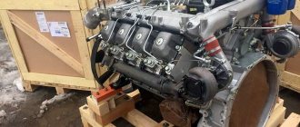
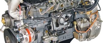
| Engine | |
| engine's type | 4-stroke, liquid-cooled, non-turbocharged |
| Engine model | YaMZ-238AK |
| Engine Manufacturer | Yaroslavl |
| Engine power, kW | 173 |
| Engine power, hp | 235 |
| Specific fuel consumption, nominal, g/hp. h | 162 |
| Fuel tank capacity, l | 540 |
| Grain bin | |
| Grain bunker capacity, cubic meters. m | 6 |
| Unloading height, mm | 2900 |
| Bunker unloading speed, l/sec | 42 |
| Dimensions and weight | |
| Length with header in transport position, mm | 17500 (6 m header) |
| Width in transport position, mm | 4400 |
| Height in transport position, mm | 3980 |
| Weight without header/with header, kg | 10990/12590 (6 m header) |
The advantages of this type of technology
- High performance, which is achieved through the use of a classic single-drum system. The threshing drum has a very large diameter and is equipped with a set of wide-cut headers. This equipment is equipped with a larger grain bin, which is characterized by quick unloading. The combine is equipped with a hydrostatic drive, which provides high maneuverability and ease of control. A large fuel tank significantly increases battery life. A modern cabin with a high level of comfort allows you to create the necessary conditions for high productivity.
- Ability to perform work in almost any conditions. The headers are equipped with a copying device and a special stone catcher, which makes it possible to carry out work even on very difficult fields. The special design of the feeder chamber and convenient reset of the deck make it possible, if necessary, to quickly restore the functionality of all mechanisms. Vibration stimulators of the bunker allow unloading in any weather conditions.
- Low losses during harvesting and the ability to obtain clean grain at the output. Due to the sufficiently large area of the concave, thorough and soft threshing is achieved. A special two-stage cleaning mechanism equipped with a fan, as well as an autonomous final grinding device, makes it possible to obtain clean and whole grain at the output. The special design of the drum threshing system, equipped with a straw walker, makes it possible to achieve the highest grain quality with fairly low energy consumption.
- High level of versatility. Thanks to a huge range of various additional equipment, combines of this model are able to harvest various types of crops. Attachments provide flexible work with non-grain crops.
- Durability and high reliability. The rational design ensures incredibly long service life under almost any conditions.
- High efficiency. An unpretentious engine and a reliable filtration system guarantee economical fuel consumption. The minimum number of lubrication points and convenient access to them ensure simplicity and efficiency of maintenance.
4.9
Upper instrument panel of the RSM-10B "Don-1500B" combine
The placement of instruments on the top instrument panel is shown in Figure 4.7.
Figure 4.7
1, 4, 10, 17 - plugs; 2,3,16-blocks of sound and light signaling; 5-key for turning on work lights; 6-key for turning on the headlight of the unloading auger; 7-key for turning on the air conditioning compressor; 8-key for turning on the windshield wiper; 9-key for turning on the signal flashing beacon; 11-fuse box; 12-panel air conditioning system; 13-volume control; 14-buzzer; 15-control of display lamps; 18-false panel;
A-charging the battery; B-engine oil pressure is below normal; B-engine water temperature is higher than normal; D-clogging of the fine filter; D-clogging the space above the straw walker; E-reserve; The storage tank is full; 3-overheating of oil in the hydraulic tank; The I-bunker is full; K-parking brake is on; The accumulator JT valve is open; M-losses are higher than normal; H-clogging of the filter of the main hydraulic system; O - air filter clogged; P-speed of the threshing drum is below normal; P-revolutions of the cleaning shaft are below normal; C-speed of the grain auger is below normal; T-revolutions of the grain auger are below normal; Straw manipulator speed is below normal - clogging of the floor auger; F-revolutions of the straw walker shaft are below normal; X-revolutions of the chopper drum of the PKN-1500B device (chopper-spreader) are below normal; The rotation speed of the floor fan of the device PKN-1500B is below normal
4.10
Instrument panel of the RSM-10B "Don-1500B" combine
The placement of instruments on the instrument panel is shown in Figure 4.8.
Figure 4.8
1-self-control mode; 2-engine speed; 3-speed combine; 4-engine oil pressure indicator; 5-handle for removing the falypanel; 6-voltmeter; 7-engine water or GTS oil temperature indicator; 8-fuel level indicator; 9-starter key; 10-mass switch; 11-control lamp for complete on/off of the Lenix unloading auger; 12,13-reserve; 14-fuse box and socket for carrying; 15-running time counter; 16 control lamp for turning the thresher on and off; 17—activation of the automatic hay dump; 18-illumination of the control panel; 19-turn on the heater; 20-marker lights; 21-vehicle headlights (on the bumper); 22-switching control of the temperature of GTS oil and engine water; 23-block of switches; 24-control lamp for turning on/off the feeder chamber; 25-button “record” the threshing drum rotation speed into memory; 26-channel switch; 27-button “reset” (technological, used when repairing the unit); 28-cleaning fan rotation speed; 29-threshing drum rotation speed
content .. 11 12 17 ..
Combine Don-1500B, Don-1200B. Adjusting Controls
content .. 37 38 39 40 ..6.5. R adjusting controls
When adjusting the steering column in height, depending on the height and working posture of the combine operator, it is necessary to turn the head on the steering wheel counterclockwise, loosen the thread of the coupling screw, set the column to the desired height and fix it by clamping the head, rotating clockwise.
When adjusting the tilt angle, you must press the pedal located on the steering column post, set the column to the required position and release the pedal.
Adjusting the brakes. During operation, the brakes, like the clutch, do not require adjustments. Wear of the friction linings is compensated by moving the piston with the actuator cylinder rod and filling
brake fluid of the resulting volume from the feed tank. When the thickness of the friction linings decreases to 5 mm or when braking signs of incomplete braking appear, the linings must be replaced with new ones.
Adjusting the parking brake involves changing the lengths of the remote control cables by screwing together the fork ends. The lengths of the cables must be adjusted so that simultaneous braking of the wheels is provided by a mechanical equalizer attached to the end of the control lever.
When adjusting the control of the range box, the control lever should be tilted forward along the machine by 3°, and the arms of the intermediate levers should make angles close to 90° with the rods connecting them. Touching the control elements of the combine harvester components must be prevented.
Adjusting the toe-in of the steering axle wheels. The wheels must be adjusted for toe-in. In this case, the difference in sizes measured at the most distant points of the rims at the level of the wheel centers should be within 0...6 mm, maintaining a smaller size in the front part of the wheels.
When adjusting the control of the starting motor, lever 7 (Fig. 96) should be set to a position 4° to the right of the vertical, and lever 5 to 8° to the right; in this case, lever 16 must be adjusted by rod 10 and set at an angle of 6° to the left from the vertical and 56° from the lever-handle 1.
To turn on the gear wheel of the starting motor gearbox, it is necessary to turn the lever-handle 1 to position A (up at an angle of 40°); to turn on the gearbox of the starting motor, lower it to position B. When turning on the main engine, the lever-handle 1 must be returned to its original position, and the starting motor is disabled.
The air damper 8 of the starting engine carburetors should be set to the “Open” position at an angle of 35°±8° from the horizontal using handle 14 and rope 12.
The fuel supply drive mechanism is adjusted using bolt 11 (Fig. 86a), located at the bottom of the drive bracket, which ensures
preloading the spring holding the lever in a given position. In this case, the force on the handle should not exceed 60 N (6 kgf).
Adjustment of the control mechanism for turning on the feeder chamber (Fig. 85) is carried out by changing the length of the rod 5 so that when the drive of the feeder chamber is turned on (moving lever 6 forward), lever 1 passes the “dead point” and rests against the boss of bracket A, and in the rear position of the lever 6 (the feeder drive is turned off), the distance between the axes of rod 5 and shaft 14 was within 14...16 mm.
6.6. Combine Don-1500B, Don-1200B. Operation of the motor-power plant
6.6.1. Basic adjustments. Adjustment of the mechanism for turning on and off the feeder chamber drive is carried out in the order specified in paragraph 3.3.10 of these instructions.
Air intake adjustment provides:
adjusting the unloading of the air intake loops by rotating bolt 7 (Fig. 62a) and unscrewing it one turn after it touches the supporting surface;
adjusting the tightness of the air intake to the radiator block by adjusting the length of the hook 25.
The engine is adjusted in accordance with the engine operating instructions.
Adjustment of the mechanism for turning on and off the threshing drive is carried out in the order specified in paragraph 3.4.1.5.
When adjusting the air conditioner compressor drive, the tension of the drive belt (Fig. 147) and the deviation of the symmetry density of the pulley grooves from the general plane are adjusted.
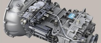
The chassis hydraulic pump drive has the following adjustments:
the tension of the drive belt 33 is adjusted (Fig. 149). The deflection in the middle of the leading branch should be 10... 15 mm with a force of 60 N;
the thickness A of the shock absorber 6 is adjusted to 13..L5 mm by rotating the washer-nut 5 and nut 4;
6.7.
Combine Don-1500B, Don-1200B. Drive wheel bridge 6.7.1. Depending on the operating conditions of the combine in the field, the first or second range of the box is used: under normal conditions, the second, and the first only in particularly difficult travel conditions (deep mud, steep climb).
When transporting on roads with improved surfaces or along compacted dirt roads, it is necessary to use the third range. In difficult road conditions during transportation, lower ranges are used to create a higher traction force on the drive wheels.
6.7.2. Any range is switched on when the combine is stationary. Before turning on, it is necessary to set the hydraulic transmission control handle to the neutral position, press the hydraulic locking pedal all the way, then turn on the desired range according to the switching diagram available in the machine’s cabin. Move the range shift knob until it stops. If the range does not turn on, turn on the hydraulic motor for a short time using the travel speed knob, set the handle to the neutral position and turn on the range. Reversing can be done in any range.
6.7.3. Adjust the speed of the machine within each range using the hydraulic transmission control handle. To reduce the load on the hydrostatic drive system, it is necessary to use the lowest range for a given machine speed.
6.7.4. If you need to drive up a steep ascent or descent, you should stop the machine in advance, turn on the reduced range and continue driving in such a way that there is no need to switch ranges on a dangerous section of the road.
6.7.5. Smooth braking of the machine can be done using a hydraulic drive. For emergency braking, mechanical brakes are used with the GST control lever moved to the neutral position.
6.7.6. Features of dismantling a hydraulic axle. Bridge service life
without major repairs, it is designed for the entire service life of the harvesting machine on which it is installed. Therefore, the need to dismantle the bridge may arise only in the event of an emergency failure, in order to examine its technical condition or to replace worn brake linings.
6.7.6.1. Disassembly of the bridge should be carried out by qualified specialists only in workshops that have the necessary equipment and tools. It is necessary to take all measures to prevent dirt and foreign objects from entering the internal cavities of the units. To moor the range boxes and final drives, eye bolts are used. The assembled bridge is moored only by the fastening brackets.
Technical examination of the range box and replacement, if necessary, of its individual parts can be carried out without removing the box from the bridge beam. To do this, you only need to dismantle the range switching mechanism 6 (Fig. 72).
Dismantling of the axle shafts (Fig. 71) is carried out without removing the range box and final drives, thanks to the presence of couplings 9. The short part of the axle shaft is removed from the box along with the cover and seal.
To facilitate removal of the range box, there are dismantling brackets. When removing, before unscrewing the four bolts securing the box, it is necessary to place a stand under its lower part, on which it is lowered, turning around the bolts. These bolts are removed after the bottom of the box rests on the stand. Before dismantling from the box, it is necessary to disconnect the hydraulic locking tube and the electrical wiring from the connecting panel.
6.7.6.2. Complete disassembly of the range box requires a certain sequence.
When dismantling the range switching mechanism, you must keep in mind that two bolts secure not only the locking body, but also the entire range switching mechanism assembly to the box body.
When dismantling the hydraulic motor mounting housing, unscrew two large