GAZ-66
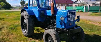
GAZ-66, colloquially “Shishiga” , which is consonant with the number 66 , where the name comes from, is a two-axle all-wheel drive truck. It has a petrol eight-cylinder four-stroke engine with a capacity of 4254 cc. cm . and power 120 hp . The front axle is switchable. The gearbox is manual, 4-speed with synchronizers in third and fourth gears. The ground clearance is quite high - it is 315 mm .
The wheelbase of the car is about 3.3 m . Turning radius 9.5 meters . The depth of the ford is 0.8 meters. The standard tank capacity is 210 l. The maximum speed reaches 90 km/h , while fuel consumption ranges from 20 to 30 liters per 100 km .
A distinctive feature of the car is the compactness of its cabin, located directly above the engine. It is mounted on hinges and tilts forward for inspection and maintenance of the engine.
Bridge Maintenance
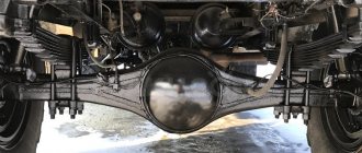
Axle maintenance consists of periodically checking the presence of oil in the crankcase, lubricating CV joints, checking the tightness of connections, and visually inspecting components for oil leaks. It is recommended to change the oil in axles every 50-70 thousand kilometers. But it must be taken into account that the GAZ 66 is often used in difficult road conditions.
If the car has to cross a ford, then if the bridges are poorly sealed, water can get into the oil. Then an oil change will be necessary.
Axles 66 are filled with transmission lubricant type TSP-14gip. If necessary, you can use other brands of gear oil, for example, TAp-15V, TAD-17i, TEp-15. When operating a vehicle at temperatures below - 35ºC, it is recommended to add 10-15% of diesel fuel from the total volume of the filling tank to the lubricant.
ZIL-131
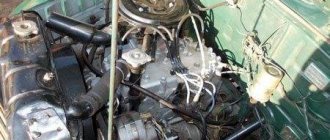
off-road truck . Initially, it was a replacement for the ZIL-157, which was obsolete by the mid-60s. The base model has a petrol V-shaped eight-cylinder engine with 150 hp. This engine is unified with the engine of another popular Soviet-era truck, the ZIL-130.
The package also includes power steering and an electro-pneumatic drive to the front axle. The gearbox is a 5-speed manual with synchronizers in the senior three gears. The truck's ground clearance is 330 mm, wheelbase is 3.3 m + 1.2 m. Maximum speed is 80 km/h . Fuel consumption ranges from 40 to 55 liters per 100 km .
Since the 1980s, ZILs with diesel engines with power from 100 hp have also been produced. and 180 hp and with an average consumption of about 25 liters per 100 km. The turning radius is about 10.5 meters. Fordability up to 1.4 meters. All six wheels are driven, front-wheel drive can be switched off.
Similarities
A significant part of both vehicles were produced for the Soviet Army. Both are reliable in their own way with a predictable resource. Of course, compared to modern trucks designed only for driving on asphalt roads, with a service life of several hundred thousand kilometers, these vehicles cannot be compared, but they have a great advantage in their cross-country ability. If maintenance is carried out promptly and accurately in accordance with the mileage, then the cars will not let you down.
The cross-country ability of both trucks is approximately the same compared to other vehicles, so they conventionally belong to the same class . Both trucks are usually equipped with an insulated kung, which can be turned into a full-fledged living compartment. Actually, for this reason, trucks are so popular among fishermen, hunters and tourists who buy them for personal needs.
The disadvantages of cars certainly include high fuel consumption. The lack of synchronizers for the first two gears imposes its own limitations on the driver - it will be difficult for those not accustomed to driving with double squeezing and re-throttle.
Differences
There are two main differences. Firstly, this is the carrying capacity of the vehicles , and as a consequence of this, the wheel formulas. The ZIL is three-axle and its load capacity is higher than that of the two-axle GAZ - three and a half tons on soil and five tons on asphalt, versus two tons. As a result, ZIL is longer - just over 7 m , in contrast to the 5.6 meter Shishiga.
The ZIL engine is not only more powerful, but also has one and a half times more torque - 41 kgf*m . GAZ has a torque of only 29 kgf*m , so, for example, starting uphill and towing trailers on GAZ is more difficult.
The second difference is the layout . GAZ has a folding cabin, initially located above the engine, while ZIL has a classic hooded cabin. Because of these differences, completely different approaches to machine maintenance and repair arise.
Rear axle malfunctions
The main failures of drive axles include increased noise during movement and oil leaks.
Repair of the rear axle on a GAZ 66 truck
- The seals of the axle shafts and the axle gearbox shank are torn or have lost their elasticity. The oil seal will also leak if the spring on it flies off;
- The fastening bolts on the bridges become loose;
- The gasket loses its tightness.
The cause of the noise is most often the final drive, but there may be other causes. Causes of howling or noise in bridges:
- The gap between a pair of final drive gears is incorrectly adjusted;
- Axle bearings are worn out;
- The axle gearbox shank nut has become loose;
- The gears of the main pair are worn out;
- The differential gears or axles are worn.
Gear wear can occur due to insufficient oil in the crankcase or its complete absence.
If there is no oil (it has leaked), then such a bridge will not travel much and will jam after a few tens of kilometers. But this is already an emergency situation - almost any driver immediately pays attention to the increased noise (howling) that appears in the car. And a bridge without lubrication will make a lot of noise before it jams. Therefore, driving with the noise of bridges is unacceptable. If it is impossible to figure out the problem yourself, the driver should contact specialists to identify the cause of the bridge malfunction.
Malfunctions of constant velocity joints
CV joint malfunctions are easily determined. When turning the wheels at speed, clicks appear in the front axle. When the hinges are heavily worn, clicks may also be heard when the wheels are turned in place. You should not allow the joint to wear out completely, as this may cause the car to lose control, which will affect traffic safety.
Axles taken from a GAZ 66 truck are widespread among fans of various SUVs. It is precisely due to its design that this all-wheel drive model has greater cross-country ability. Thus, the rear and front axles of the GAZ 66 provide the vehicle with ground clearance of 31.5 cm and the ability to cross a ford whose depth is 80 cm.
What's better
The trucks are complementary to each other. GAZ-66 is lighter and more maneuverable, while ZIL-131 is more load-bearing. As such, one does not have advantages over another - they are not all given for free. For example, on a GAZ you can take away a smaller amount of inventory or equipment than on a ZIL, and if we talk about a residential kung, then the ZIL has more capacity. But at the same time, GAZ has much lower fuel consumption and is cheaper to operate.
Due to the smaller turning radius and lower weight, the GAZ is easier to maneuver. It also has a higher top speed. At the same time, the cross-country ability of the ZIL is higher, both due to the fact that it has two more wheels and due to a more powerful engine. If you go camping, fishing or on an expedition with a small group, then the GAZ-66 looks more preferable. If the group is large, and capacity plays a decisive role compared to speed and fuel consumption, then the ZIL-131 will have a clear advantage.
Auto and motorcycleComment
Rear axle and final drive Gas 3307 and Gas 3309.
Hello dear friends! Today we will get acquainted with the main gear and the rear axle of the Gas 3307 and Gas 3309 cars. The rear axle and gearbox of the Gas 53 are the same, only the difference is in the number of teeth of the driven gear: the Gas 53 has 41 teeth, while the Gas 3307 has 41 teeth. and Gas 3309, the number of teeth is 37. And there is also a difference in the brake pads, and, accordingly, the drum. The pads and drum on the Gas 53 are not much, that’s the only difference. Otherwise there is no difference, everything is the same. So, we can safely say that today’s article will also concern the rear axle and Gas 53, too.
To increase durability, axles are equipped with a hypoid type main gear. The drive gear relative to the driven gear is shifted downwards by 32 mm. To prevent large deformations of the driven gear, the main gear is equipped with an adjustable stop. The main gear and differential are mounted in a separate gear housing, which is loosely inserted into the hole in the axle housing and secured with bolts.
The rear axle gearboxes of the Gas 3307, Gas 3309 and Gas 53 vehicles differ from the Gas 66 gearbox only in the design of the differential. On the Gas 3307, Gas 3309 and Gas 53 vehicles, a conventional bevel differential with four satellites is used, and on the Gas 66 vehicle, a self-locking cam differential is installed to increase cross-country ability. The separator has 24 radial holes arranged in two rows in a checkerboard pattern, into which crackers are installed. Between the rows of holes for the crackers on the outer and inner surfaces of the separator, there are locking rings that prevent the crackers from rotating around their axes, and also keep them from falling out of the cage when assembling the differential. The outer sprocket is freely installed in the cup hole, and the inner sprocket is installed in the holes of the separator and the outer sprocket.
The rear axle housing of Gas 3307, Gas 3309, Gas 53 and Gas 66 cars consists of two stamped halves welded along the horizontal axis of the bridge. This design ensures ease of installation and dismantling of the unit. The wheel axles at the ends of the crankcase of the Gas 3307, Gas 3309 and Gas 53 cars are butt welded, and on the crankcase of the Gas 66 car they are attached to the crankcase using studs.
Reducer Gas 53, 3307, 3309.
Reducer Gas 66.
Operating principle of the Gas 66 gearbox.
Cam differentials.
This is one of the very first limited-slip differentials and deserves a detailed look. The first mechanism of this type was designed in 1929 by engineers from the Mac Power Divider company specifically to improve the maneuverability of 4x4 trucks with a carrying capacity of 5 to 10 tons and was initially used as a center differential. Beginning in 1948, these mechanisms began to be used as interwheel mechanisms. Let's look at the design and operating principles of this DPT using the example of the GAZ-66 cross-axle differential
The differential consists of internal (2) and external (3) sprockets and 24 plungers (6), located in the radial holes of the separator (5) in two rows with a half-step shift around the circumference. The separator is made as one piece with the left differential housing cup (1 on the left). The plungers engage with the outer cams of the inner sprocket and the inner cams of the outer sprocket (4 cams of the inner (bottom) and outer (top) sprockets). The sprockets are connected to the output shafts. On the outer sprocket (3), six cams are evenly spaced around the circumference (4 at the top), which engage with the plungers of both rows. The inner sprocket (2) has two independent rows of cams (4 at the bottom); each row has six cams evenly spaced around the circumference.
The cams of one row are shifted along the circumference relative to the cams of the other row by half a step. The plungers perform the function of satellites. If the angular velocities of the axle shafts are the same, then the plungers remain motionless relative to the separator and sprockets; and when the car passes a turn, one sprocket overtakes the leading separator, and the other lags behind it. In this case, the separator, ahead of the lagging sprocket, causes the plungers to move in the radial direction as they move along the surface of the cams. The opposite ends of the plungers act in a similar manner on the inclined surfaces of the other sprocket, causing it to rotate at an angular velocity greater than the angular velocity of the separator. The presence of relative motion between the differential parts will cause friction forces to appear on the end surfaces of the plungers in contact with the surfaces of the cam races.
As a result, there will be a redistribution of forces in the direction of increasing them on the lagging driven cage and decreasing them on the leading one, i.e. The cams and plungers form the fulcrum point for the wheel with the most traction. As a result, a larger Mk will be applied to the axle shaft of the wheel that has better grip (lagging behind). The separator and cam cages were made of chromium-nickel-tungsten steel 18ХНВА, and the plungers were made of ball-bearing chromium steel ШХ15. The working surfaces of these parts were cemented to prevent scuffing.
This DBT has a constant KB, but there is an interesting feature. When one of the wheels of the bridge slips (with the second one lagging behind), the value of Kb is less than when the other one slips. So, when the right wheel of a GAZ-66 slips, Kb = 3.1; and when the left wheel (associated with the internal sprocket) slips, Kb = 2.1. Soviet designers specially set the differential in such a way that when the right wheel, which often ends up on a slippery side, slips, the torque is redistributed to the left wheel, which is on a dry road, by three times. times higher than to the right.
Thus, this DPT has two constant KB, or scientifically speaking: asymmetric blocking properties. This feature is common to all cam differentials because they have similar designs.
When testing various models of cam differentials of domestic and foreign production, carried out in the USSR, it was found that their Kb is 2...3. Cam DPTs are often confused with the so-called “freewheel differentials”, which are freewheel mechanisms (MSH) consisting of one drive and two driven coupling halves. These are completely different mechanisms both in structure and operating principles. Their main difference is that the cam differential, when turning the car on a road with good grip, provides the axle wheels with rotation at different angular speeds, but at the same time redistributes torque to each of them. In this mode, each of its three kinematic links (body and two output shafts) rotates at different angular velocities.
In the same driving mode, the MCX also provides the wheels with rotation at different angular speeds, but at the same time the Mk is distributed only to the inner (relative to the center of rotation) wheel, and the outer one rolls in a driven mode. During this period, its two kinematic links (the driving clutch and the driven half-clutch connected to the axle shaft of the inner wheel) are connected to each other, and the second driven half-clutch is disconnected from the mechanism, which ensures faster rotation of the outer wheel. Thus, when driving in a turn, the cam DPT drives both wheels of the axle, and the MCX only drives one of them.
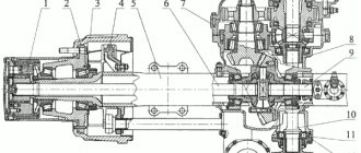
Gearbox and differential of the front and rear axles of the GAZ-66.
Fig.1.
1. Bearing 807813K2; 2. Differential separator; 3. Outer retaining ring of the differential lock; 4. Differential lock; 5. Internal differential crayon guide ring; 6. Internal differential sprocket with radial cams; 7. Outer rear axle differential sprocket; 8. Differential cup; 9. Drive and driven gears of the main pair of the rear axle (set after grinding in); 10. Clutch with outer rings of drive gear bearings assembled; 11. Oil removal ring for the front axle drive gear oil seal; 12. Left power steering mounting bracket; 13. Flange with reflector assembly; 14. Bolt M12-4hx45; 15. Nut M24x1.5; 16. Special washer; 17. Bolt M12x60 securing the drive gear bearing coupling; 18. Main gear drive gear cuff assembly; 19. Rear axle front housing cover; 20. Gasket; 21. Front drive gear bearing of the main pair of the rear axle 27308У1; 22. Spacer ring for the main gear drive gear bearings (for spare parts); 23. Adjustment gasket for the drive gear bearings of the rear axle main gear, 0.2 mm thick (for spare parts) (As required); 24. Bearing 27709U1; 25. Gasket 0.10 mm thick; 26. Bearing GOST 520-89; 27. Retaining ring; 28. Bolt M12x1.25-4hx47.
Parts of the rear axle of trucks Gas 3307, 3309, 53.
Fig.2.
1. Nut M30x1.5-5N6N; 2. KG1 plug; 3. Oil pickup tube spring; 4. Oil pickup tube plate; 5. Tube; 6. Washer 12.FROM OST 37.001.115-75; 7. Bolt M12x1.25-6gx38; 8. Stop plate; 9. Bolt M6-6gx18 OST 37.001.123-96; 10. Nut M10-6N OST 37.001.124-93; 11.Bolt M10-6gx30 OST 37.001.123-96; 12. Stopper KG 2; 13.Differential bearing nut; 14. Axle shaft gasket; 15. Rear axle axle shaft; 16.Bolt M10-6gx22; 17.Washer 14.FROM OST 37.001.115-75; 18.Nut M14x1.5 Sp; 19. Bearing nut; 20. Lock washer for the rear wheel hub bearing nut; 21. Rear wheel hub bearing nut with pin assembly; 22. Hairpin M14x1.5-Spkh35; 23. Plug KG1/2; 24. Cotter pin wire 1.6x350; 24. Rear axle differential assembly (spare parts kit); 25. Bolt M8-6gx14; 26. Locking plate for the differential bearing nut; 27. Bolt M16-4hx105; 28. Rear axle gear housing with bearing caps assembled; 29. Rear axle housing assembly; 30. Rear axle gear housing gasket; 31. Breather assembly; 32. Adjusting screw for the driven gear stop of the main pair of the rear axle assembly; 33. Bushing; 34. Spring ring of the driven gear stop bushing; 35. Driven gear stop adjusting screw.
The box-section rear axle housing of the GAZ-3309, GAZ-3307 vehicles is welded from stamped steel casings, to which are welded the rear cover, spring cushions, axles with flanges for installing brake mechanisms and wheel hubs, and a reinforcement for mounting the gearbox. The design of the gearbox and rear axle hubs is shown in Fig. 2 and 3.
Fig.3.
Gearbox and differential of the rear axle GAZ-3307, 3309.
1 — front cover; 2 — coupling with outer rings of bearings; 3, 19, 23, 31, 34 — bolts; 4, 20 — gaskets; 5, 9, 29, 33 — nuts; 6 - drive gear; 7- flange adapter; 8 — flange with reflector; 10 - cuff; 11 — oil sump ring; 12, 15, 17, 21 — bearings; 13 — adjusting shims; 14 — adjusting ring; 16, 38 - plugs; 18 — retaining ring; 22 — axle gear; 24, 36 — support washers; 25, 28 — differential boxes (right and left); 26 — crosspiece; 27 — driven gear; 30 — differential bearing cover; 32 — locking plate; 35 — satellite; 37 — adjusting screw; 39 - bushing; 40 — oil receiving tube; 41 — gear housing.
The rear axle gearbox of GAZ-3307, GAZ-3309 is assembled in a separate cast housing 41 (see Fig. 1) made of high-strength cast iron, which is installed in the hole in the axle housing and secured with bolts 34. The gearbox housing contains a clutch of 2 bearings with drive gear b, flange 8 and flange adapter 7, as well as a differential, the housing of which consists of right 25 and left 28 boxes connected by bolts 23. The driven gear 27 is secured to the left box with bolts and nuts.
The main gears of the GAZ-3309, 3307 rear axle gearbox are hypoid. The axis of the drive gear is shifted downwards relative to the axis of the driven gear by 32 mm. The preload of the drive gear bearings is adjusted by ring 14 located between the inner races of tapered bearings 12 and 15. To prevent excessive deformation of the driven gear, a stop is installed in the crankcase, adjustable by screw 37.
The differential assembly with tapered bearings 21 is installed in the sockets of the gearbox housing, closed with covers 30 secured with bolts. The preload of the differential bearings is adjusted with nuts 33. The same nuts are used to adjust the lateral clearance in the meshing of the main gear gears.
In the differential housing of the gearbox of the GAZ-3307, 3309 bridge, gears 22 axle shafts and four satellites 35 are installed, placed on the spikes of the crosspiece 26. Support washers 24 and 36 are installed under the satellites and axle gears. Axle shafts 2 are inserted into the splined holes of the axle gears (Fig. 2) , attached by a flange to the wheel hub with nuts and studs.
The rear wheel hubs rotate on tapered roller bearings 4 and 5, mounted on the axles of the GAZ-3307, 3309 rear axle. The bearing is fastened and adjusted with a nut 15 screwed onto the threaded end of the crankcase axle. The adjusting nut is locked with washer 16 and nut 11. On the inside of the hub there is a cuff 11 installed, which prevents lubricant from leaving the hub, and an oil deflector 8 with an O-ring and a tube to protect the brake linings from oil.
Main gear Gas 3307, 3309, 53.
Fig.4.
1. Left satellite box; 2. Nut M12x1.25-4N5N; 3. Lock nut; 4. Bearing GOST 520-89; 5. Oil catcher; 6. Washer; 7. Bolt M8-6gx22; 8. Drive and driven gears of the main pair of the rear axle; 9. Adjustment gasket; 10. Coupling of the bearings of the drive gear of the main pair of the rear axle; 11. Bearing GOST 520-71; 12. Front rear axle housing cover; 13. Washer 12.FROM OST 37.001.115-75; 14. Bolt M12-4hx45; 15. Cotter pin 4x40; 16. Nut M24x1.5-4N5N; 17. Washer for the drive gear of the main pair of the rear axle; 18. Flange with reflector assembly; 19. Marking plate; 20. Oil seal for the drive gear of the main pair of the rear axle with a spring assembly; 21. Oil removal ring for the rear axle drive gear oil seal; 22. Gasket for the rear axle drive gear bearing clutch; 23. Adjustment ring; 24. Bearing 27709U1; 25. Cotter pin wire 1.2x550; 26. Rear axle differential gear box bolt. 27. Right satellite box; 28. Bearing for the guide end of the drive gear; 29. Support washer for the rear axle axle gear; 30. Retaining ring; 31. Rear axle axle gear; 32. Support washer for the rear axle differential satellite; 33. Rear axle differential satellite; 34. Differential satellite spider; 35. Drive gear mounting bolt.
Rear axle hub GAZ-3307, 3309
Rice. 5.
1 - bolt; 2 - axle shaft; 3 - gasket; 4, 5 — bearings; 6 - brake drum; 7 — ABS rotor; 8 — oil deflector with sealing ring and tube; 9, 18 — nuts; 10 - bushing; 11 - cuff; 12 — rear brake; 13 - thrust ring; 14 — hub: 15, 17 — bearing nuts; 16 — lock washer.
Removing the rear axle of GAZ-3307, GAZ-3309 cars.
Removing the bridge from the vehicle must be carried out in the following order:
- — loosen the rear wheel nuts;
- — disconnect the propeller shaft from the drive gear flange adapter (from the drive gear flange);
- — disconnect the parking brake drive cables from the equalizer;
- — disconnect the brake system hoses, remove the brake pipes;
- — disconnect electrical cables and ABS sensors;
- — unscrew the nuts securing the spring ladders, remove the ladders, pads and spring linings;
- — before disassembling, you must unscrew the drain plug and drain the oil.
Disassembly of the rear axle of GAZ-3309, 3307 must be carried out in the following order:
- — unscrew the nuts securing the axle shafts and remove the axle shafts using the dismantling bolts;
- — remove the axle flange gaskets;
- - Unscrew the lock nut of the outer hub bearing, remove the lock washer, unscrew the inner nut of the hub bearing;
- — remove the brake drum and hub assembly;
- — press out the cuff, thrust washer and inner ring of the bearing. The cuff must be replaced when the working edge hardens or there are cracks due to rubber aging;
- — in case of bearing replacement, press out the outer ring of the inner bearing from the rear axle hub of GAZ-3307, 3309 using a puller and gripper. Place the gripper legs under the end of the ring and spread them all the way by screwing the bolt into the axle. Remove the bearing ring by rotating the puller screw;
- — press out the outer ring of the outer hub bearing in the same way;
- — Unscrew the fastening bolts and remove the oil deflector assembly;
- — unscrew the nuts, remove the bolts securing the ends to the crankcase flange and remove the brake assembly and oil deflector brackets;
- — Unscrew the nuts of the mounting bolts and remove the drive gear flange adapter;
- — Unscrew the bolts securing the gearbox to the crankcase and remove the gearbox using the dismantling bolts; — remove the gearbox gasket; — unscrew the breather;
- — to remove a worn cuff bushing from the crankcase axle, remove a layer of metal from the surface of the bushing with a depth of at least 3 mm in two diametrically opposite places and cut the bushing with a chisel without damaging the surface of the axle crankcase axle axle.
Dismantling the rear axle gearbox GAZ-3307, 3309.
The gearbox must be disassembled in the following order:
- — unscrew the control hole plug;
- — unscrew the plug of the oil intake pipe;
- — Unscrew the fastening bolt and remove the spring, plate and tube from the oil channel;
- — unlock and unscrew the adjusting screw of the stop; — remove the bushing and spring ring from the adjusting screw;
- — Unscrew the bolts securing the locking plates of the differential bearing nuts, remove the locking plates;
- — unscrew the adjusting nuts 33 (see Fig. 3.) using a special wrench.
Disassembly of the rear axle gearbox of GAZ-3309, 3307 must be carried out in the following order:
- — unscrew the nut on the shank of the drive gear;
- — unscrew the nut and remove the washer;
- — remove the flange of the drive gear of the rear axle reducer;
- — remove the front cover, gasket and oil sump ring;
- — remove the bearing coupling together with the inner ring of the front tapered bearing;
- — remove the adjusting ring;
- — in case of replacement, compress the inner ring of the rear tapered bearing using a puller, installing the liners into it. To remove the bearing ring, compress the support nuts with the support nuts until the shoulders of the liners contact the end of the inner ring of the bearing or the thrust shoulder of the inner ring rollers; to do this, it is necessary to remove the rollers.
Disassembly of the GAZ-3307, 3309 axle differential must be carried out in the following order:
- - Unscrew the nuts and remove the bolts securing the driven gear to the differential boxes;
- — remove the driven gear from the differential box;
- — bend the locking plate, unscrew the bolt and remove the oil catcher;
- — in case of replacement, press the inner rings of the bearings from the right and left differential boxes. To do this, you need to use a puller with liners;
- - Unscrew the bolts securing the differential boxes, disconnect the boxes, remove the crosspiece, axle gears, support washers, remove the support washers and satellites from the crosspiece.
Adjusting the final drive of the rear axle GAZ-3307, 3309.
The bearings and gearing of the main gears of GAZ-3309, 3307 are adjusted at the factory and, as a rule, do not require adjustment in operation. Their adjustment is necessary only after reassembling the bridge and when replacing any parts or when there is significant wear on the bearings.
The lateral clearance in the meshing of the main gears, which has increased due to tooth wear, cannot be reduced by adjustment, as this will lead to a disruption of the meshing of the teeth. This will result in increased noise or tooth breakage.
Play in tapered bearings should be eliminated without disturbing the relative position of the driven and drive gears. Below is the procedure for making various adjustments.
Adjusting the preload of the drive gear bearings of the GAZ-3307, 3309 gearbox.
The need for bearing adjustment can be determined by the presence of axial play in the drive gear shaft. Axial play is measured using an indicator device (the flange adapter is removed) when moving the drive gear shaft from one extreme position to another, and in the absence of a device, by rocking the flange by hand.
If there is axial play of the drive gear in tapered bearings of more than 0.03 mm, you must first tighten the flange nut. To do this, unscrew the nut and tighten it to a torque of 280-400 Nm (28-40 kg/cm). If, after tightening the nut, the moment of resistance to rotation of the drive gear of the main drive of the rear axle is greater than the norm specified below, it means that the ends of the inner rings of the bearings and the adjusting ring are heavily worn.
In this case, to adjust the bearings, it is necessary to select a thicker ring. Adjusting rings, produced in thicknesses of 12.10-12.94 mm, are divided into 22 groups. The thickness of the rings of adjacent groups differs by 0.04 mm. If the thickness of the adjusting ring exceeds the required one, then tightening the nut will not eliminate the backlash and increase the resistance when the drive gear rotates in the bearings.
In this case, it is necessary to adjust the preload of the axle main drive bearings by reducing the thickness of the adjusting ring installed between the inner rings of the tapered bearings.
To do this you need to do the following:
- — remove the drive gear assembly;
- — unscrew the flange mounting nut;
- — remove the flange, oil seal cover, oil sump ring, inner ring of the outer bearing and adjusting ring. Select an adjusting ring with a thinner thickness.
The reduction in ring thickness should be equal to the sum of the axial play measured by the indicator and the value of 0.05 mm (bearing preload).
Reassemble the coupling in reverse order and tighten the nut. When tightening the nut, it is necessary to rotate the drive gear of the main gear reducer GAZ-3309, 3307 for proper installation of the rollers in the bearings. Tighten the nut with the torque specified above, and one of its slots should coincide with the hole for the cotter pin.
You cannot even turn the nut back a little so that the hole for the cotter pin matches the slot of the nut, since insufficient tightening may cause the inner ring of the outer bearing to rotate, wear out the adjusting ring, and, as a result, increase the backlash of the drive gear.
Check the tightness of the bearings. With proper adjustment, the moment of resistance to rotation of the drive gear should be in the range of 1.5-3.0 Nm (0.15-0.30 kg/cm). The test should be carried out using a dynamometer.
To do this, clamp the coupling in a vice, hook the dynamometer hook onto the flange hole and smoothly turn the gear. The readings on the dynamometer scale should be in the range of 29-51 N (2.9-5.1 kgf).
If the moment of resistance to rotation of the bearings is within the normal range, you need to tighten the nut and install the drive gear assembly into the rear axle housing, otherwise you need to repeat the adjustment.
If it turns out that the torque resistance to rotation is less than the required one, it is necessary to reduce the thickness of the adjusting ring, and if it exceeds the required one, then it is necessary to select a ring of greater thickness.
If suddenly you haven’t found something, or you simply don’t have time to search, then I recommend reading the articles in the “ GAS Repair ” categories. I am sure you will find the answer to your question, and if not, write in the comments the question you are interested in, I will definitely answer.
Add a comment