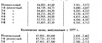
Applicability of YaMZ crankshafts
YaMZ engines of the YaMZ-236, 238 families of all modifications and configurations, when supplied both to assembly plants and to spare parts, are equipped with crankshafts with main and connecting rod journal sizes of 2 nominal sizes. On one crankshaft, a combination of 2 nominal journal sizes is allowed, and all journals of the same name must have the same size. With the 2nd nominal size, additional markings of the crankshaft are used: • main journals – “K1” or “K”; • connecting rod journals – “Ш1” or “Ш”. The specified marking is applied on the untreated surface of the 5th cheek of the crankshaft (for 6, 8 cylinder engines) after the part number made in the forging.
Possible cases of marking crankshafts depending on the sizes of the main and connecting rod journals are presented in the table:
| Additional markings for the crankshaft | —-* | "Ш1" | "K1" | "Ш1 К1" |
| Diameter of main journals, mm | 110,00-0,022 | 110,00-0,022 | 109,75-0,022 | 109,75-0,022 |
| Main liner marking | 236-1005170-B and 236-1005171-B | 236-1005170-B and 236-1005171-B | 236-1005170-B and 236-1005171-B | 236-1005170-В-Р1 and 236-1005171-В Р1 |
| Thickness of the main liner, mm | 2,965-0,012 | 2,965-0,012 | 3,090-0,012 | 3,090-0,012 |
| Diameter of connecting rod journals, mm | 88,00-0,022 | 87,75-0,022 | 88,00-0,022 | 87,75-0,022 |
| Marking of connecting rod bearing | 236-1004058-B | 236-1004058-В-Р1 | 236-1004058-B | 236-1004058-В-Р1 |
| Connecting rod bearing thickness, mm | 2,490-0,012 | 2,615-0,012 | 2,490-0,012 | 2,615-0,012 |
YaMZ engines of the YaMZ-240 families of all modifications and configurations, when supplied both to assembly plants and for spare parts, are equipped with crankshafts with dimensions of main bearings and connecting rod journals of 2 nominal sizes. On one crankshaft, a combination of 2 nominal journal sizes is allowed, and all journals of the same name must have the same size. With the 2nd nominal size, additional markings of the crankshaft are used:
- main supports - “K1” or “K”;
- connecting rod journals - “Ш1” or “Ш”.
The specified marking is applied on the front end of the 1st cheek of the crankshaft after the part number made in the forging and on the outer diameter of the 4th support.
Possible cases of marking crankshafts depending on the sizes of the raceways of the main bearings and connecting rod journals are presented in the table:
| Additional markings for the crankshaft | —-1 | "Ш1" | "K1" | "Ш1 К1" |
| Diameter of main journals, mm | 191,92-0,029 | 191,92-0,029 | 191,42-0,029 | 191,42-0,029 |
| Rolling bearing marking2 | 2VO2622134 LM or 2VO2622134 EM | 2VO2622134 LM or 2VO2622134 EM | 2VO2622134 LM or 2VO2622134 EM | 2VO2622134 LM or 2VO2622134 EM |
| Diameter of connecting rod journals, mm | 88,00-0,022 | 87,75-0,022 | 88,00-0,022 | 87,75-0,022 |
| Marking of connecting rod bearing | 236-1004058-B | 236-1004058-В-Р1 | 236-1004058-B | 236-1004058-В-Р1 |
| Connecting rod bearing thickness, mm | 2,490-0,012 | 2,615-0,012 | 2,490-0,012 | 2,615-0,012 |
Note: 1 - dimensions and markings of the bearings when using a crankshaft with raceways of the main bearings and crankpins of the 1st nominal size; There is no additional marking. 2- marking LM, L1M in the bearing designation indicates the material of the cage - brass; EM, E1M - polyamide. The serial number of the shaft and the abbreviated designation of the part are marked on the outer diameter of the 4th support, next to the treadmill. At the end of the shaft on the flywheel side (at a distance of 32 mm from the shaft axis) the serial number of the month and year of manufacture (the last two digits) are marked.
YaMZ engines of the YaMZ-840, 850 families of all modifications and configurations, when supplied both to assembly plants and to spare parts, are equipped with crankshafts with dimensions of main bearings and connecting rod journals of 2 nominal sizes. On one crankshaft, a combination of 2 nominal journal sizes is allowed, and all journals of the same name must have the same size. With the 2nd nominal size, additional markings of the crankshaft are used:
- main supports - “K2” or “K”;
- connecting rod journals - “Ш2” or “Ш”.
The specified marking is applied on the 1st cheek of the crankshaft after the part number made in the forging. Possible cases of marking crankshafts depending on the sizes of the raceways of the main bearings and connecting rod journals are presented in the table:
| Additional markings for the crankshaft | —-* | "Sh2" | "K2" | "Sh2 K2" |
| Diameter of main journals, mm | 117,00+0.018 -0,008 | 117,00+0.018 -0,008 | 116,75+0.018 -0,008 | 116,75+0.018 -0,008 |
| Main liner marking | 840.1005170 and 8406.1005171 | 840.1005170 and 8406.1005171 | 840.1005170 and 8406.1005171 | 840.1005170 and 8406.1005171 |
| Thickness of the main liner, mm | 4,000+0.050 -0,062 | 4,000+0.050 -0,062 | 4,125+0.050 -0,062 | 4,125+0.050 -0,062 |
| Diameter of connecting rod journals, mm | 90,00+0.018 -0,008 | 89,75+0.018 -0,008 | 90,00+0.018 -0,008 | 89,75+0.018 -0,008 |
| Marking of connecting rod bearing | 840.1004058 | 840.1004058-Р2 | 840.1004058 | 840.1004058-Р2 |
| Connecting rod bearing thickness, mm | 2,490-0,012 | 2,615-0,012 | 2,490-0,012 | 2,615-0,012 |
Note: * - dimensions and markings of the liners when using a crankshaft with main and connecting rod journals of the 1st nominal size; There is no additional marking. The serial number of the shaft is stamped on the 1st cheek of the crankshaft using the impact method. The shaft numbering starts from “1” from the beginning of each calendar year.
Complete set of crankshafts for the main types of YaMZ-236,238 engines
| Crankshaft assembly (with main and connecting rods) inserts) | Steel grade, thermoform | Marking on the 5th cheek of the crankshaft | Marking on the sticker | Distinctive features |
| YaMZ-236M2, YaMZ-236G, YaMZ-236A1 | ||||
| 236-1005009-D2 (236-1000107-B4) | 50G normalization | YaMZ-236-1005015-E YaMZ-236-1005015-E K1 YaMZ-236-1005015-E Sh1 YaMZ-236-1005015-E KSh1 | 236-1005012-A 23600 1005012 010 | There is one boss on the 2nd cheek |
| YaMZ-236N, YaMZ-236NE, YaMZ-236NE2, YaMZ-236NB, YaMZ-236ND, YaMZ-236B, YaMZ-236BE, YaMZ-236BE2 | ||||
| 236НЭ-1005009 (236НЭ-1000107) 236Н-1005009 (236N-1000107)4 | 50G improved (42H1FA improved, nitrided) | YaMZ-236N-1005015 YaMZ-236N-1005015 K1 YaMZ-236N-1005015 Sh1 YaMZ-236N-1005015 KSh1 | 236NE-1005012-A 23626 1005012 000 | There is one boss on the 2nd cheek, two bosses on the 1st cheek |
| YaMZ-236D | ||||
| 236D-1005009 (236D-1000107) | 50G improved | YaMZ-236D-1005015 YaMZ-236D-1005015 K1 YaMZ-236D-1005015 Sh1 YaMZ-236D-1005015 KSh1 | 236D-1005012-A 23605 1005012 000 | There is one boss on the 2nd cheek, two bosses on the 1st cheek, a deep hole of 51 to a depth of 52 at the rear end, pin 236D-10051322 |
| YaMZ-236DK | ||||
| 236DK-1005009-30 (236DK-1000107-30) | 50G improved | YaMZ-236DK-1005015 YaMZ-236DK-1005015 K1 YaMZ-236DK-1005015 Sh1 YaMZ-236DK-1005015 KSh1 | 236DK-1005012-B 23695 1005012 020 | There is one boss on the 2nd cheek, two bosses on the 1st cheek, cone at the front end of the shaft |
| YaMZ-7601.10 | ||||
| 7601.1005009 (7601.1000107) | 42H1FA improved, nitriding | YaMZ-7601-1005015 YaMZ-7601-1005015 K1 YaMZ-7601-1005015 Sh1 YaMZ-7601-1005015 KSh1 | 7601-1005012 76010 1005012 000 | There is one boss on the 2nd cheek, the hole for the bearing is 62 |
| YaMZ-7601.10-01 | ||||
| 7601.1005009-10 (7601.1000107-10) | 42H1FA improved, nitriding | YaMZ-7601-1005015 YaMZ-7601-1005015 K1 YaMZ-7601-1005015 Sh1 YaMZ-7601-1005015 KSh1 | 7601-1005012-10 76010 1005012 010 | There is one boss on the 2nd cheek, the hole for the bearing is 62 cone at the front end of the shaft |
| YaMZ-238M2, YaMZ-238N, YaMZ-238ND2, YaMZ-238ND3, YaMZ-238ND4, YaMZ-238NP, YaMZ-238G, YaMZ-238GM2, YaMZ-238AM2 (except YaMZ-238AM2-3), YaMZ-238IM2, YaMZ- 238KM2 (except YaMZ-238KM2-2, -3), YaMZ-238VM | ||||
| 238-1005009-G2 (238-1000107-B4) | 50G normalization | YaMZ-238-1005015-E YaMZ-238-1005015-E K1 YaMZ-238-1005015-E Sh1 YaMZ-238-1005015-E KSh1 | 238-1005012-A 23800 1005012 010 | There is one boss on the 2nd cheek |
| YaMZ-238B, YaMZ-238BV, YaMZ-238BL, YaMZ-238BE, YaMZ-238D, YaMZ-238DE, YaMZ-238ND5, YaMZ-238L | ||||
| 238BE-1005009 (238BE-1000107) 238N-1005009 (238N-1000107)4 | 50G improved (42H1FA improved, nitrided) | YaMZ-238N-1005015-U3 YaMZ-238N-1005015-U K1 YaMZ-238N-1005015-U Sh1 YaMZ-238N-1005015-U KSh1 | 238BE-1005012 23825 1005012 000 | There is one boss on the 2nd cheek, two bosses on the 1st cheek |
| YaMZ-238AK (except 4th set), YaMZ-238AM2-3, YaMZ-238EK | ||||
| 238AK-1005009-20 (238AK-1000107-20) | 50G normalization | YaMZ-238AK-1005015-20 YaMZ-238AK-1005015-20 K1 YaMZ-238AK-1005015-20 Sh1 YaMZ-238AK-1005015-20 KSh1 | 238AK-1005012-B 23891 1005012 020 | There is one boss on the 2nd cheek, a cone at the front end of the shaft |
| YaMZ-238BK, YaMZ-238DK | ||||
| 238DK-1005009-20 (238DK-1000107-20) | 50G improved | YaMZ-238DK-1005015-20-U YaMZ-238DK-1005015-20-U K1 YaMZ-238DK-1005015-20-U Sh1 YaMZ-238DK-1005015-20-U KSh1 | 238DK-1005012-B 23895 1005012 020 | There are two bosses on the 1st cheek, one boss on the 2nd cheek, cone at the front end of the shaft |
| YaMZ-238BE2, YaMZ-238DE2, YaMZ-7511.10, YaMZ-7512.10, YaMZ-7513.10, YaMZ-7514.10 | ||||
| 238DK-1005009-20 (238DK-1000107-20) | 42H1FA improved, nitriding | YaMZ-238DK-1005015-30 YaMZ-238DK-1005015-30 K1 YaMZ-238DK-1005015-30 Sh1 YaMZ-238DK-1005015-30 KSh1 | 238DK-1005012-V 23895 1005012 030 | There are two bosses on the 1st cheek, one boss on the 2nd cheek, a cone at the front end of the shaft, bearing hole 62 |
| YaMZ-238KM2-2, YaMZ-238KM2-3, KhTZ | ||||
| 238-1005009-D (238-1000107-D) | 50G normalization | YaMZ-238-1005015-D YaMZ-238-1005015-D K1 YaMZ-238-1005015-D Sh1 YaMZ-238-1005015-D KSh1 | 238-1005012-D 23800 1005012 050 | There is one boss on the 2nd cheek, two bosses on the 1st cheek, deep hole 51 to a depth of 52 at the rear end |
| YaMZ-238AK-4, Kherson | ||||
| 238AK-1005009-30 (238AK-1000107-30) | 50G normalization | YaMZ-238AK-1005015-31 YaMZ-238AK-1005015-31 K1 YaMZ-238AK-1005015-31 Sh1 YaMZ-238AK-1005015-31 KSh1 | 238AK-1005012-G 23891 1005012 040 | There is one boss on the 2nd cheek, a cone at the front end of the shaft, bearing hole 62 |
Notes: *1 - in the “Engine” column only the model and modification of the power unit are shown, but it should be understood that the crankshaft corresponding to a certain modification is installed on all configurations of this engine, except when the configuration is indicated; *2 - on all other engine modifications, the crankshaft pin 7511-1005132 is installed; *3 - the letters “N” and “U” are stamped using the impact method.
*4 - discontinued
Complete set of crankshafts for the main types of YaMZ-240 engines
| Engine | Crankshaft assembly (with main bearings and connecting rod bearings) | Steel grade, heat treated | Marking on the 4th support on the outer diameter next to treadmill | Marking on the front end of the 1st crankshaft cheek |
| YaMZ-240M2 YaMZ-240NM YaMZ-240NM2 YaMZ-240PM2 YaMZ-240BM2 | 240-1005000-A2 (240-1000107-B6) | 60HFA-SH TU 14-1-1547-75 | G3 G3K1 G3SH1 G3K1SH1 | G4 G4K1 G4SH1 G4K1SH1 |
Complete set of crankshafts for the main types of YaMZ-840, 850 engines
| Engine | Crankshaft assembly (with main bearings and connecting rod bearings) | Steel grade, heat treated | Marking on the 4th support on the outer diameter next to treadmill | Marking on the front end of the 1st crankshaft cheek |
| YaMZ-8401.10 | 840.1005010 (840.1000107) | 42HMFA TU 14-132-213-2002 | YaMZ-840-1005010 YaMZ-840-1005010 K2 YaMZ-840-1005010 Sh2 YaMZ-840-1005010 KSh2 | 2 gears at the rear end of the shaft; insert at the front end of the shaft. |
| YaMZ-845.10 YaMZ-8451.10 | 845.1005010 (845.1000107) | 42HMFA TU 14-132-213-2002 | YaMZ-840-1005010 YaMZ-840-1005010 K2 YaMZ-840-1005010 Sh2 YaMZ-840-1005010 KSh2 | 2 gears at the front end of the shaft; 1 gear at the rear end of the shaft; without insert. |
| YaMZ-850.10 YaMZ-8501.10 YaMZ-8502.10 | 850.1005010 (850.1000107) | 42HMFA TU 14-132-213-2002 | YaMZ-840-1005010 YaMZ-840-1005010 K2 YaMZ-840-1005010 Sh2 YaMZ-840-1005010 KSh2 | 2 gears at the rear end of the shaft; 1 gear at the front end of the shaft; without insert. |
Design + replacement of the crankshaft of the YaMZ-238 diesel engine
To balance the engine and unload the main bearings from the inertial forces of the moving masses of the pistons and connecting rods and unbalanced centrifugal forces, counterweights are installed on the cheeks of the crankshaft, with which the shaft is balanced. In addition, the balancing system includes two remote masses, one of which is made in the form of a recess on the flywheel mounted on the rear end of the crankshaft, the other is a counterweight mounted on the front end of the crankshaft.
Axial fixation of the shaft is carried out by four bronze half-rings installed in the grooves of the rear main support. To prevent rotation, the lower half rings fit into pins pressed into the rear main bearing cover with their grooves.
The toe and shank of the crankshaft are sealed with rubber self-tightening cuffs.
A crankshaft gear and a front counterweight are pressed onto the front end of the crankshaft, secured with a nut with a tightening torque of 176.4 - 294 Nm (18 - 30 kgf m).
The crankshaft of the YaMZ-238BE2, YaMZ-238DE2 engines has a cone at the front end. A hub is installed on the cone, on which a liquid vibration damper and a pulley are attached. When repairing an engine, it should be remembered that impacts and dents on the torsional vibration damper will disable it, which will inevitably lead to breakage of the crankshaft. The extinguisher should be stored and transported only in a special container in an upright position.
The YaMZ-238BE, YaMZ-238DE engines are equipped with a crankshaft 238BE-1005009 (marking 238N-1005015-U), and the YaMZ-238BE2, YaMZ-238DE2 engines are equipped with a crankshaft 238DK-1005009-30 (marking 238DK-100501 5-30) .
The crankshaft in the forging is marked on the 5th cheek.
The crankshaft journals can be of two nominal sizes and therefore the following marking options and the use of corresponding liners are possible.
| Crankshaft marking | 238DK – 1005015-30 or 238N – 1005015-U | 238DK – 1005015-30 Ш1 or 238Н – 1005015-У Ш1 | 238DK – 1005015-30 K1 or 238N – 1005015-U K1 | 238DK – 1005015-30 Ш1К1 or 238Н – 1005015-У Ш1К1 |
| Diameter of main journals, mm | 110-0,022 | 110-0,022 | 109,75-0,022 | 109,75-0,022 |
| Marking of main bearings | 236-1005170-B and 236-1005171-B | 236-1005170-B and 236-1005171-B | 236-1005170-В Р1 and 236-1005171-В Р1 | 236-1005170-В Р1 and 236-1005171-В Р1 |
| Thickness of the main liner, mm | 2,965-0,012 | 2,965-0,012 | 3,090-0,012 | 3,090-0,012 |
| Diameter of connecting rod journals, mm | 88,00-0,022 | 87,75-0,022 | 88,00-0,022 | 87,75-0,022 |
| Marking of connecting rod bearing | 236-1004058-B | 236-1004058-B | P1 236-1004058-B | 236-1004058-В Р1 |
| Connecting rod bearing thickness, mm | 2,490-0,012 | 2,615-0,012 | 2,490-0,012 | 2,615-0,012 |
Note: The letters “DK”, “N”, “U”, “Sh”, “K” and the numbers “30”, “1” are stamped when marking using the impact method.
FLYWHEEL
The flywheel is cast from gray cast iron. The flywheel is marked in a recess on the non-working surface of the casting. The following types of flywheels can be installed on engines:
− 238-1005115-K (for a ring gear with a module of 4.25);
− 238-1005115-N (for a ring gear with a module of 3.75).
These flywheels assembled with toothed rims are not interchangeable with each other.
Flywheel 238-1005115-K (for a ring gear with a 4.25 module) is installed with a starter model 2501.3708-01, and flywheel 238-1005115-N (for a ring gear with a 3.75 module) is installed with a starter model 2501.3708-21.
The flywheel is bolted to the crankshaft. A high-hardness steel plate is installed under the bolts (one for all bolts). The absence of self-loosening of the bolts is ensured by a tightening torque of 235-255 N m (24-26 kgf m). To accurately fix the flywheel relative to the crankshaft journals, two pins are used; in this case, the holes marked on the flywheel and on the plate must coincide with the offset pin on the crankshaft. The offset pin is located in the plane of the first crank. The marking on the plate in the form of a dot should be on the outside.
Twelve radial holes in the flywheel are designed to rotate the crankshaft during engine adjustments. Access to the holes is possible with the flywheel housing lower hatch cover removed.
CONNECTING ROD
Rice. 3 — Steel connecting rod, I-section, with an oblique connector of the lower head.
The connecting rod is finally processed together with the cap, so the connecting rod caps are not interchangeable. The cylinder serial number is stamped on the cap and connecting rod on the side of the short bolt, and pairing marks are stamped on the side of the long bolt in the form of a number that is the same for the connecting rod and cap.
Replaceable liners are installed in the lower head of the connecting rod, and a steel-bronze bushing is pressed into the upper head.
The bushing is processed after being pressed into the connecting rod.
The YaMZ-238BE2, YaMZ-238DE2 engines are equipped with connecting rods 7511.1004045-02 (marking on the rod 7511.1004045), in which the distance between the axes of the holes in the upper and lower heads is increased by 15 mm, bevels on the upper head, the diameter of the hole under the piston is increased to 52 mm pin and there is no oil channel in the rod.
A steel-bronze bushing 7511.1004052-21 with an outer diameter of 56 mm is pressed into the upper head of the connecting rod.
The YaMZ-238BE, YaMZ-238DE engines are equipped with connecting rods 236-1004045-B3 (marking 236-1004045-B2) with an oil channel in the rod.
A steel-bronze bushing 840.1006026-10 with an outer diameter of 54 mm is pressed into the upper head of the connecting rod.
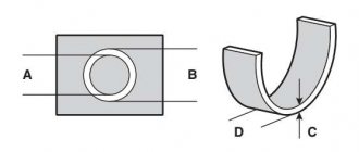
INSERT
The main bearing shells of the crankshaft and the lower head of the connecting rod (Fig. 4) are replaceable, thin-walled, have a steel base and a working layer of lead bronze.
Rice. 4
The upper and lower crankshaft main bearing shells are not interchangeable. The upper liner has a hole for oil supply and a groove for its distribution.
The connecting rod lower head bearings are interchangeable.
On YaMZ-238BE, YaMZ-238DE engines, oil is supplied through a hole in the liner to the bushing of the upper connecting rod head and the piston pin.
CLEANING THE CONNECTING ROD CAVITIES
Each time you remove the crankshaft from the engine, clean the cavities of the connecting rod journals by first removing plugs 2 (Fig. 4) that cover the cavities. Replace the plugs with new ones; their reuse is not allowed.
Rice. 5
Before installing the plugs, file away the swelling of the metal at the edges of the holes from the previous core, wash the shaft and blow out the oil channels. Press the plugs to a depth of 5–6 mm from the edge of the hole, and then poke them inside the hole at three points equally spaced around the circumference to prevent the plugs from spontaneously pressing out.
INSTALLING THE CRANKSHAFT ON THE ENGINE
When installing the crankshaft on the engine, ensure that the dimensions of the bearing shells match the dimensions of the shaft journals (see table).
Before installation, ensure that the external surfaces and internal cavities of the crankshaft and other mating surfaces are clean. Lubricate the journals and working surfaces with clean engine oil.
To facilitate installation of the flywheel in the correct position relative to the crankshaft, the number “8” for eight-cylinder engines is marked on the flywheel hub, which, during assembly, is aligned with the number “2” at the end of the crankshaft.
Main bearing caps are not interchangeable; When installing them, make sure that the mark on the cover matches the mark on the block.
When tightening the main bearing caps, start with the vertical bolts and tighten in two steps with a torque after re-tightening of 430...470 Nm (43...47 kgf m), then tighten the horizontal bolts in two steps with a final tightening torque of 90...120 Nm (9... 12 kgf m).
Before tightening the rear thrust main bearing, level the axial clearance by slightly tightening the bearing cover with bolts and move the crankshaft back and forth in the axial direction until it stops using a crowbar, first forward and then back, leveling the position of the cover. After tightening the bolts, check the axial clearance with a feeler gauge. It should be the same on both sides of the lid.
REPLACING THE CRANKSHAFT GEAR
The crankshaft gear can be replaced without removing the crankshaft from the engine.
Rice. 6
Remove the drive pulley. To remove the hub with pulley and damper from the tapered end of the crankshaft of an eight-cylinder engine, use the puller shown in Figure 6. With the pulley and front block cover removed, compress the front counterweight and gear using a puller. Before installation, heat the gear and front counterweight to a temperature of 105...155ºС and consistently press them until they stop using a special device.
Steel 40Х GOST 4543-71 Harden, temper 34…39 HRCе
All necessary parts can be purchased in our catalog
Crankshaft YaMZ-238,238D,B,N,BE Turbo (PJSC Avtodizel) 238-1005009-G3
Available Wholesale and retail Code: 238-1005009-G3
Buy
Find out partner prices
- +74852594588 MULTICHANNEL
- +79023339310
- +88003504588 FREE CALL
- Terms of payment and delivery
- Schedule
- Contacts
- Return and exchange conditions
238BE-1005009 YaMZ (Avtodiesel) steel crankshaft, made by hot stamping. All shaft surfaces are nitrided, the depth of the nitrided layer is not less than 0.35 mm. Used on engine models YaMZ-238D-1, YaMZ-238D-2, YaMZ-238B-1, YaMZ-238BV and their modifications.
Weight: 115.00 kg.
Complete set of crankshafts for the main types of YaMZ-236,238 engines
| Crankshaft assembly (with main and connecting rods) inserts) | Steel grade, thermoform | Marking on the 5th cheek of the crankshaft | Marking on the sticker | Distinctive features |
| YaMZ-236M2, YaMZ-236G, YaMZ-236A1 | ||||
| 236-1005009-D2 (236-1000107-B4) | 50G normalization | YaMZ-236-1005015-E YaMZ-236-1005015-E K1 YaMZ-236-1005015-E Sh1 YaMZ-236-1005015-E KSh1 | 236-1005012-A 23600 1005012 010 | There is one boss on the 2nd cheek |
| YaMZ-236N, YaMZ-236NE, YaMZ-236NE2, YaMZ-236NB, YaMZ-236ND, YaMZ-236B, YaMZ-236BE, YaMZ-236BE2 | ||||
| 236НЭ-1005009 (236НЭ-1000107) 236Н-1005009 (236N-1000107)4 | 50G improved (42H1FA improved, nitrided) | YaMZ-236N-1005015 YaMZ-236N-1005015 K1 YaMZ-236N-1005015 Sh1 YaMZ-236N-1005015 KSh1 | 236NE-1005012-A 23626 1005012 000 | There is one boss on the 2nd cheek, two bosses on the 1st cheek |
| YaMZ-236D | ||||
| 236D-1005009 (236D-1000107) | 50G improved | YaMZ-236D-1005015 YaMZ-236D-1005015 K1 YaMZ-236D-1005015 Sh1 YaMZ-236D-1005015 KSh1 | 236D-1005012-A 23605 1005012 000 | There is one boss on the 2nd cheek, two bosses on the 1st cheek, a deep hole of 51 to a depth of 52 at the rear end, pin 236D-10051322 |
| YaMZ-236DK | ||||
| 236DK-1005009-30 (236DK-1000107-30) | 50G improved | YaMZ-236DK-1005015 YaMZ-236DK-1005015 K1 YaMZ-236DK-1005015 Sh1 YaMZ-236DK-1005015 KSh1 | 236DK-1005012-B 23695 1005012 020 | There is one boss on the 2nd cheek, two bosses on the 1st cheek, cone at the front end of the shaft |
| YaMZ-7601.10 | ||||
| 7601.1005009 (7601.1000107) | 42H1FA improved, nitriding | YaMZ-7601-1005015 YaMZ-7601-1005015 K1 YaMZ-7601-1005015 Sh1 YaMZ-7601-1005015 KSh1 | 7601-1005012 76010 1005012 000 | There is one boss on the 2nd cheek, the hole for the bearing is 62 |
| YaMZ-7601.10-01 | ||||
| 7601.1005009-10 (7601.1000107-10) | 42H1FA improved, nitriding | YaMZ-7601-1005015 YaMZ-7601-1005015 K1 YaMZ-7601-1005015 Sh1 YaMZ-7601-1005015 KSh1 | 7601-1005012-10 76010 1005012 010 | There is one boss on the 2nd cheek, the hole for the bearing is 62 cone at the front end of the shaft |
| YaMZ-238M2, YaMZ-238N, YaMZ-238ND2, YaMZ-238ND3, YaMZ-238ND4, YaMZ-238NP, YaMZ-238G, YaMZ-238GM2, YaMZ-238AM2 (except YaMZ-238AM2-3), YaMZ-238IM2, YaMZ- 238KM2 (except YaMZ-238KM2-2, -3), YaMZ-238VM | ||||
| 238-1005009-G2 (238-1000107-B4) | 50G normalization | YaMZ-238-1005015-E YaMZ-238-1005015-E K1 YaMZ-238-1005015-E Sh1 YaMZ-238-1005015-E KSh1 | 238-1005012-A 23800 1005012 010 | There is one boss on the 2nd cheek |
| YaMZ-238B, YaMZ-238BV, YaMZ-238BL, YaMZ-238BE, YaMZ-238D, YaMZ-238DE, YaMZ-238ND5, YaMZ-238L | ||||
| 238BE-1005009 (238BE-1000107) 238N-1005009 (238N-1000107)4 | 50G improved (42H1FA improved, nitrided) | YaMZ-238N-1005015-U3 YaMZ-238N-1005015-U K1 YaMZ-238N-1005015-U Sh1 YaMZ-238N-1005015-U KSh1 | 238BE-1005012 23825 1005012 000 | There is one boss on the 2nd cheek, two bosses on the 1st cheek |
| YaMZ-238AK (except 4th set), YaMZ-238AM2-3, YaMZ-238EK | ||||
| 238AK-1005009-20 (238AK-1000107-20) | 50G normalization | YaMZ-238AK-1005015-20 YaMZ-238AK-1005015-20 K1 YaMZ-238AK-1005015-20 Sh1 YaMZ-238AK-1005015-20 KSh1 | 238AK-1005012-B 23891 1005012 020 | There is one boss on the 2nd cheek, a cone at the front end of the shaft |
| YaMZ-238BK, YaMZ-238DK | ||||
| 238DK-1005009-20 (238DK-1000107-20) | 50G improved | YaMZ-238DK-1005015-20-U YaMZ-238DK-1005015-20-U K1 YaMZ-238DK-1005015-20-U Sh1 YaMZ-238DK-1005015-20-U KSh1 | 238DK-1005012-B 23895 1005012 020 | There are two bosses on the 1st cheek, one boss on the 2nd cheek, cone at the front end of the shaft |
| YaMZ-238BE2, YaMZ-238DE2, YaMZ-7511.10, YaMZ-7512.10, YaMZ-7513.10, YaMZ-7514.10 | ||||
| 238DK-1005009-20 (238DK-1000107-20) | 42H1FA improved, nitriding | YaMZ-238DK-1005015-30 YaMZ-238DK-1005015-30 K1 YaMZ-238DK-1005015-30 Sh1 YaMZ-238DK-1005015-30 KSh1 | 238DK-1005012-V 23895 1005012 030 | There are two bosses on the 1st cheek, one boss on the 2nd cheek, a cone at the front end of the shaft, bearing hole 62 |
| YaMZ-238KM2-2, YaMZ-238KM2-3, KhTZ | ||||
| 238-1005009-D (238-1000107-D) | 50G normalization | YaMZ-238-1005015-D YaMZ-238-1005015-D K1 YaMZ-238-1005015-D Sh1 YaMZ-238-1005015-D KSh1 | 238-1005012-D 23800 1005012 050 | There is one boss on the 2nd cheek, two bosses on the 1st cheek, deep hole 51 to a depth of 52 at the rear end |
| YaMZ-238AK-4, Kherson | ||||
| 238AK-1005009-30 (238AK-1000107-30) | 50G normalization | YaMZ-238AK-1005015-31 YaMZ-238AK-1005015-31 K1 YaMZ-238AK-1005015-31 Sh1 YaMZ-238AK-1005015-31 KSh1 | 238AK-1005012-G 23891 1005012 040 | There is one boss on the 2nd cheek, a cone at the front end of the shaft, bearing hole 62 |
Notes: *1 – in the “Engine” column only the model and modification of the power unit are shown, but it should be understood that the crankshaft corresponding to a certain modification is installed on all configurations of this engine, except when the configuration is indicated; *2 – on all other engine modifications, the crankshaft pin 7511-1005132 is installed; *3 – the letters “N” and “U” are stamped using the impact method.
*4 - discontinued
Characteristics
Technical characteristics of YaMZ-236, YaMZ-238 engines
Home To the list of references
Technical characteristics of the YaMZ-236, YaMZ-238 engines
| Technical characteristics of YaMZ-236, YaMZ-238 engines | ||
| engine's type | Four-stroke, compression ignition | |
| Number of cylinders | 6 | 8 |
| Cylinder arrangement | V-shaped, with a camber angle of 90° | |
| 1-4-2-5-3-6 | 1-5-4-2-6-3-7-8 | |
| Cylinder diameter, mm | 130 | |
| Piston stroke, mm | 140 | |
| Cylinder displacement, l | 11,15 | 14,86 |
| Compression ratio | 16,5 | |
| Rated power, l. With. | 180 | 240 |
| Nominal speed, rpm | 2100 | |
| Maximum torque, 1 kGm | 67 | 90 |
| Number of revolutions at maximum torque, rpm | No more than 1500 | |
| Minimum idle speed, rpm | 450 — 55 | |
| Maximum idle speed, rpm | 2225 — 2275 | |
| Minimum specific fuel consumption, g/e.l.h. | 175 | |
| Method of mixture formation | Direct injection | |
| The combustion chamber | Splitless type in piston | |
| Valve timing (crankshaft rotation angle), degrees: | — | |
| - inlet valve | — | |
| - opening | 20 to v. m.t. | |
| - closing | 56 after n.m.t. | |
| - Exhaust valve | — | |
| - opening | 56 BC | |
| - closing | 20 after b.m.t. | |
| Number of valves per cylinder | One inlet and one outlet | |
| Valve head diameter, mm: | — | |
| — inlet | 61,5 | |
| - graduation | 48 | |
| Valve lift, mm | 13,5 | |
| Valve location | Upper | |
| Gap between the end of the valve and the toe of the rocker arm (in a cold state), mm | 0,25 — 0,30 | |
| Camshaft | Common to both cylinder banks, gear driven | |
| Fuel supply equipment | Split type | |
| Booster pump | Piston type driven by eccentric camshaft | |
| Setting advance angle, degrees | 18 or 20. Indicated at the injection end of the advance clutch housing. Installation accuracy ± 1° | |
| Injection advance clutch | Automatic, centrifugal, direct action | |
| High pressure fuel pump | Six-plunger | Eight-plunger |
| Plungers | Spool type, plunger diameter 9 mm, stroke 10 mm | |
| Operating order of the fuel pump sections | 1-4-2-5-3-6 | 1-3-6-2-4-5-7-8 |
| Speed regulator | Centrifugal, all-mode | |
| Injectors | Closed, with multi-hole nozzles | |
| Pressure of the beginning of lifting of the nozzle needle, kg/cm2 | 150+5 | |
| Fuel filters: | ||
| — pre-cleaning | With replaceable cotton roving filter element; mounted outside the engine | |
| — fine cleaning | With a replaceable filter element made of wood flour on a pulverba-kelite basis; a bypass valve is installed in the filter cover | |
| Fuel | Diesel, low sulfur according to GOST 4749-49 | |
| Pressure in the oil system at nominal speed, kg/cm2 | 4 — 7 | |
| Pressure in the oil system at minimum idle speed kg/cm | At least 1 | |
| Pressure in the oil system after long-term operation kg/cm2 | Not lower than 3.5 - at nominal speeds and 0.5 - at minimum | |
| Oil | Diesel according to GOST 5304-54 and 8581-63 with VNII NP-360 additive in the amount of 6-8%: in winter DP-8 and DS-8, and in summer DP-11 and DS-11 | |
| Lubrication system | Mixed. The main and connecting rod bearings of the crankshaft, camshaft bearings, connecting rod upper end bushings, valve rocker arm bushings, oil pump idler gear bushings, spherical rod bearings and pusher bushings are lubricated under pressure. Cylinder bores, gears, rolling bearings and camshaft lobes are splash lubricated | |
| Air filter | Inertia-oil with contact element | |
| Coolant temperature | 75-95 | |
| Oil filters: | ||
| - rough cleaning | With metal mesh filter element | |
| — fine cleaning | Centrifugal with jet drive | |
| Oil cooling system | Oil cooler mounted outside the engine | |
| Engine cooling system | Liquid, closed type, with forced circulation of coolant | |
| Fan and its drive | Axial type, gear driven | |
| Starting device | Electric starter ST103 with a power of 7 hp. With, | |
| Generator | G107-B, 24 V, power 500 W | |
| Relay regulator | PP107 | |
| Cylinder block | Cast from alloy cast iron complete with upper crankcase | |
| Cylinder liners | Wet type, cast from alloy cast iron | |
| Crankshaft | Steel, with screwed counterweights; The surfaces of the necks are hardened so-called. | |
| Number of crankshaft bearings | 4 | 5 |
| Main bearings | Slides, with replaceable inserts | |
| Connecting rod bearings | Slides, with replaceable inserts | |
| Piston | Aluminum | |
| Number of piston rings: | — | |
| - compression | 3 | |
| — oil scraper | 2 | |
| Piston pins | Floating, axial movement limited by retaining rings | |
| Connecting rods | Steel, I-section, bronze bushings pressed into the upper head | |
| Flywheel | Cast iron with steel ring gear for starting the engine with a starter | |
| Crankcase ventilation | Carried out through the breather located at the rear end of the left row of the cylinder block | |
| Number of camshaft supports | 4 | 5 |
| Overall dimensions, mm: | — | |
| - length | 1020 | 1245 |
| - width | 1000 | |
| — height (with air filter) | 1245 | |
| Dry weight, kg: | — | |
| — without auxiliary equipment (according to GOST 491-55) | 800 | 1000 |
| — with gearbox, clutch and accessories | 1140 | 1377 |
Repair of the crankshaft of YaMZ-238PM and YaMZ-238FM engines
The crankshaft is replaced if there are cracks of any size and location, scoring on the connecting rod and main journals and runout of the main journals that cannot be eliminated by grinding to the last repair size. The runout of the middle journals relative to the outer ones is allowed no more than 0.08 mm. The check is carried out with an indicator with the outer journals installed on the prisms.
If at least one main or one connecting rod journal is worn beyond the permissible limit (Table 1), as well as if at least one of the connecting rod journals has deep
If there are any scratches or burrs, all main or connecting rod journals are ground to one repair size. The number of the repair size of the connecting rod journals may differ from the number of the repair size of the main journals.
Grinding of the crankshaft journals for repair dimensions is carried out within the limits given in table. 1. In this case, the following conditions must be met:
the transition of the cylindrical sections of the necks into fillets should be smooth (fillet radius 5.5-6.0 mm), without undercuts, burns, or rough marks; the surface roughness of the journals should not exceed 0.20 microns, the roughness of the fillets should not be lower than 0.32 microns;
the radius of the axes of all cranks of the shaft should be 70±0.12 mm;
the non-parallelism of the axes of the middle journals relative to the common axis of the outer journals should not exceed 0.010 mm, the non-parallelism of the axes of the connecting rod journals relative to the common axis of the outer journals should not exceed 0.015 mm;
Ovality, taper, concavity and barrel-shapedness of the main and connecting rod journals are not allowed to exceed 0.01 mm.
The absence of cracks is checked with a magnetic flaw detector with mandatory subsequent demagnetization.
Whenever you remove the crankshaft from the engine to replace the bearings, it is recommended to clean the connecting rod journal cavities by first removing the plugs that cover the cavities. Reuse of plugs is not permitted.
Before installing the plugs, the swollen metal at the edges of the holes from the previous core is filed down, the shaft is washed and the oil channels are blown out. The plugs are pressed in to a depth of 5-6 mm and punched inside the hole at three points evenly spaced around the circumference to prevent the plugs from spontaneously pressing out.
Rice. 10. Mandrel for installing the piston into the cylinder liner: I - cylinder liner; 2— cylinder block; 3— crimping device; 4 — piston rings; 5 - piston
The crankshaft gear is replaced when there is contact destruction of the teeth, chips, cracks, development in the form of grooves, as well as when the lateral clearance in engagement with the camshaft gear is over 0.3 mm. The crankshaft gear can be replaced without removing the crankshaft from the engine. With the pulley and front block cover removed, the front counterweight and gear are pressed together using a puller. Before installation, the gear and front counterweight must be heated to a temperature of 105 ° C and successively pressed until they stop using a special device.
Replacement of main and connecting rod bearing shells. The crankshafts of YaMZ engines have high wear resistance. After 80-100 thousand kilometers, preventive replacement of the liners is recommended, which will extend the service life of the crankshaft before regrinding. To replace the main and connecting rod bearings, the engine is removed from the vehicle. The bearings must be replaced under conditions that prevent dirt from getting on the bearings and crankshaft journals. New liners must have nominal dimensions.
The connecting rod bearings are changed in order, starting with the bearing of the first cylinder. The removed liners are carefully inspected. If there are damages that are unnatural wear and tear, their cause is determined. The oil channels of the crankshaft are cleaned of contaminated oil and deposits, and the journal is wiped with a soft, clean cloth (the journal should be smooth, without deep marks, burrs, or enveloping metal).
Before installing the bearings on the shaft, the shaft journal and bearings are lubricated with engine oil. The connecting rod bearing fastening bolts are tightened with a torque of 20-22 kgf-m.
The main bearing shells can be replaced using a pin without removing the crankshaft. Pin
It is a steel rod 25 mm long, 6 mm in diameter and has a head with a diameter of 15 mm and a height of 3 mm. To remove the upper main bearing shell, a pin is inserted into the hole in the oil channel of the main journal. To push out the liner, the crankshaft is rotated. To install the insert into the bed, it is placed on the neck and, with manual effort, partially inserted into the gap between the neck and the bed. Then the pin is inserted into the hole in the oil channel and, turning the shaft, the liners are installed in place. Vertical bolts securing the main bearing caps are tightened with a torque of 43-47 kgf-m, and horizontal bolts with a torque of 10-12 kgf-m.
The need to replace the liners is determined by the amount of wear in thickness and diametrical gaps in the mating (Table 2). If the wear in thickness exceeds 0.05 mm or if the diametrical gap is more than 0.23 mm, the liners are replaced with new ones. The thickness of the liner is measured in its middle. The clearance is checked by measuring the diameter of the crankshaft journal and the inner diameter of the bearing (after tightening the cover bolts). Bearing shells are replaced if they have nicks, cracks, or collapse of the tendril to hold the shell in the socket.
table 2
When reinstalling, the liners are installed only in those beds from which they were previously removed. The upper and lower crankshaft bearing shells are not interchangeable, since the upper shells have holes for oil supply and grooves for its distribution. Both connecting rod lower head shells are interchangeable.
To repair the crankshaft, six repair sizes of liners are provided. The repair size stamp is applied on the back side of the liner near the joint. The repair size number of the liner must correspond to the repair size number of the corresponding crankshaft journal. The crankshaft bearing shells should only be replaced completely on the entire engine.
Restoring valve tightness. To restore the tightness of the valves, you need to remove the cylinder head (or heads) as indicated above; clean them of oil and carbon deposits, and then apply marks on the valve plates so that during assembly they can be installed in the same seats. Using the device (Fig. 11), compress the springs, remove the crackers and, having released the springs, remove the valves, thoroughly clean them of carbon deposits, wash them in kerosene and carefully inspect them to determine the extent of repair.
Rice. 11. Device for removing and installing gas distribution valves: 1 - thrust screw; 2 — pressure plate; 3 - handle
With minor wear and small holes on the chamfer of the valve and seat, in the absence of warping of the valve plate and burnouts, the tightness of the valve can be restored by grinding with a paste, which is prepared by thoroughly mixing 1.5 parts (by volume) of green silicon carbide micropowder 63C-M28 OST 2- 144—71 with one
part of summer motor oil and 0.5 part of diesel fuel L-0.2-40 GOST 305-82. Before use, the grinding mixture is thoroughly mixed, since the micropowder can precipitate.
The lapping process consists of a back-and-forth rotation of the valve using a special lapping drill, which automatically changes the direction of rotation. If you don't have a special drill, you can use a regular hand drill. In all cases, the connection of the device (for turning the valve) with the valve plate is carried out using a rubber suction cup.
To grind in, apply a thin layer of paste evenly to the chamfer, lubricate the valve stem with clean engine oil and put it in place. If grinding is carried out with a hand drill, then, pressing lightly, turn the valve 1/3 of a turn, then in the opposite direction by 1/4 of a turn, etc. Grinding cannot be done in a circular motion. The valve must be periodically lifted to apply a new portion of lapping paste to its chamfer. An external sign of satisfactory lapping is the receipt on the valve and seat chamfers of a continuous matte belt with a width of at least
1.5 mm. Tearing of the matte strip and the presence of scratches on it are not allowed.
After finishing the grinding, the valves and seats should be washed with kerosene and wiped dry, and after installing the valves
and springs in place, check for leaks. To do this, pour kerosene into the inlet and outlet windows and leave for 3 minutes. Leakage or seepage of kerosene when turning the valve to any angle is not allowed.
You can also check the quality of the grinding using a pencil. To do this, 10-15 lines are applied across the chamfer with a soft graphite pencil at regular intervals. Carefully insert the valve into the seat, press it firmly and at the same time turn it 1/4 turn. After this, all the lines on the chamfer should be erased. If the test results are unsatisfactory, the valve grinding must be repeated. If the tightness of the valve cannot be ensured by lapping or lapping alone is not enough (traces of gas breakthrough, depressions on the working chamfers, etc.), then the seats and valves are sanded and then lapping is repeated. To grind valve seats, use a grinding device or an electric drill equipped with the necessary grinding wheel and mandrel. In this case, the centering of the grinding wheel is carried out by the shank of the mandrel, which fits into the valve guide sleeve. If valve guide bushings need to be replaced, the seats are ground only after replacing the bushings.
content .. 1 2 3 8 ..