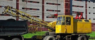
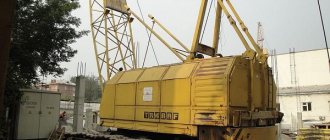
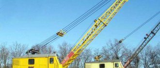
The KS-4361 crane is based on a special all-wheel drive wheeled chassis equipped with dual pneumatic tires. The production of equipment under the Yurginets brand began in the 70s. The machine is designed to perform installation and loading work in open areas, as well as in warehouses. Production was carried out at factories in the cities of Yurga and Kamyshin.
It is allowed to operate equipment with a grab with a capacity of up to 1.5 m³. The working body is mounted on a boom with a length of 10.5 or 15.5 m. The maximum load weight in the bucket is 3700 kg. It is possible to install tower-boom equipment with a structure height of 15 or 20 m. In this case, the machine uses a steerable boom with a reach of 10.5 m. The listed equipment is not included in the standard delivery package.
Technical and lifting characteristics
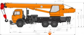
Overall dimensions of the KS-4361A crane and technical characteristics:
- length - 14500 mm;
- width (with removed supports) - 3150 mm;
- height (with the boom lowered to the transport position) - 3030 mm;
- installation weight - 23700 kg;
- turning radius - at least 12 m;
- load capacity when installing supports - 16 tons;
- load capacity without additional supports - 9 tons;
- hook lifting height - 4.0-8.8 m (depending on the reach);
- speed of lifting and lowering the load - up to 10 m/min;
- platform rotation speed - 0.5-2.8 rpm.
Technical characteristics of the crane KS-4362
Load capacity, t:
| .on supports: | |
| ..at the smallest hook reach | 16 |
| ..at maximum hook reach | 3,5 |
| .without supports: | |
| ..at the smallest hook reach | 8 |
| ..at maximum hook reach | 2 |
| Hook reach, m: | |
| ..least | 3,9 |
| ..greatest | 10 |
| Hook lifting height, m: | |
| ..at the smallest hook reach | 12,1 |
| ..at maximum hook reach | 8,5 |
| Speeds: | |
| ..lifting the main hook, m/min | 3,5 — 7,4 |
| ..lowering, m/min | 0,1 — 15 |
| ..rotation speed of the turntable, rpm | 0,4 — 1,2 |
| ..crane movement by self-propelled, km/h | 2; 15 |
| Maximum support load, kN | 208 |
| Maximum axle load, kN | 140 |
| Smallest turning radius (outer wheel), m | 12,3 |
| Maximum angle of ascent of the track, degrees | 15 |
| Engine: | |
| ..brand | SMD-14A |
| ..power, hp | 75 |
| Wheel track, m: | |
| ..front | 2,4 |
| ..rear | 2,4 |
| Crane weight, t | 23 |
| Including counterweight, t | 0,4 |
Load capacity when moving and the climbing angle overcome during travel in transport position
| Load capacity when moving, t* | 8 |
| Percentage of rated load capacity | 50 |
| Climbing angle of the track (without load), degrees. | 12 |
| Slope of the site during crane operation, degrees. | 3 / 1,5** |
* — Load capacity is indicated with the boom located along the axis of the crane. ** — The denominator is the permissible angle of inclination of the crane when working on outriggers.
Characteristics of the main and replaceable boom equipment of the KS-4362 crane
| Main boom length, m | 12,5 |
| Maximum length of extended boom, m | 25 |
| Length of unsteered jib, m | 4 |
| Tower boom equipment: | |
| ..maximum length of additional boom, m | 10 |
| ..maximum tower length, m | 16,6 |
| Grab capacity, m3 | 1,5 |
The power plant of the KS-4362 crane consists of a diesel engine 1 and a generator 3 , connected to each other by a gear transmission 2 - 4 .
Power plant of the crane KS-4362
The kinematic diagrams of the main winch and the auxiliary lift winch are the same. The drive is carried out from an electric motor 1 connected by a coupling 2 to a two-stage gearbox with gears 4 - 5 and 6 - 7 . The output shaft of the gearbox is connected to drum 3 . Unlike the auxiliary winch, the main winch is equipped with a shoe brake, the brake of the auxiliary winch is combined with a clutch.
Kinematic diagram of the auxiliary lifting winch of the KS-4362 crane
The boom winch is driven by an electric motor 1 connected by a coupling 2 to a two-stage gearbox with gears 5 - 4 and 5 - 6 . Gear 3 - 4 is a worm gear, and 5 - 6 is a gear. The brake is combined with clutch 2 , the output shaft of the gearbox is connected to drum 7 .
Kinematic diagram of the jib winch of the KS-4362 crane
The turning mechanism consists of an engine 11 , a three-stage gearbox with gears 7 - 8 , 5 - 6 , 3 - 4 , a runner gear 2 and a ring gear 1 . Electric motor 11 is connected to the gearbox by coupling 10 ; 9 is installed on the input shaft of the gearbox .
Kinematic diagram of the rotation mechanism of the KS-4362 crane
The movement mechanism consists of an electric motor 15 , a two-stage gearbox with gears 12 - 16 , 13 - 9 ; a two-speed gearbox with gears 20 - 21 , 8 - 22 , 7 - 23 and two axles: front A and rear B. The axles are connected to the gearbox by cardan shafts 19 and 24 . The front axle is equipped with swivel wheels, the rear axle is equipped with fixed wheels. In this regard, axle shafts 1 and 2 of the front axle have articulated joints. Both axles include a main gear 5 - 6 , 17 - 18 and a differential gear 3 - 4 .
Kinematic diagram of the movement mechanism of the KS-4362 crane
The jib winch of the KS-4362 crane is driven by electric motor 6 of the MTKR6 brand, the power from which is transferred to drum 24 through a two-stage gearbox 15 . The electric motor shaft is connected to the gearbox using a gear coupling. 5 is mounted on a key on the electric motor shaft , which is connected to the drive coupling half 4 . The driven coupling half is also a brake pulley 3 ; it is also secured to the input shaft of the gearbox using a key. The two-stage gearbox has two pairs of gears: worm gear 7 - 14 and gear gear 13 - 1 . The worm shaft is secured in the gearbox housing using tapered bearings 9 . The worm wheel sits on a common shaft with the gear of the second pair of gears, which is a gear shaft 13 . The fit of the worm wheel on the gear shaft is splined; the gear shaft rests on the gearbox housing with ball bearings 16 - 17 . Gear 1 , which engages with gear shaft 13 , also has a splined fit on shaft 19 . The connections between the output shaft and drum 24 are geared. The drum shaft is freely supported by ball bearings on the bracket 22 and the output shaft 19 of the gearbox.
| Jib winch of crane KS-4362 | Crane rotation mechanism KS-4362 |
In the rotation mechanism of the KS-4362 crane, the lubrication system of the mechanism is original. The kinematic transmission chain of the drive includes an electric motor 15 , a three-stage gearbox 18 , a sliding gear 27 ; engaging with the ring gear of the slewing ring. The electric motor shaft 15 and the input gear shaft 7 of the gearbox 18 are connected by a gear coupling 11 . The driven coupling half has a spline fit on the input shaft. Next to the driven coupling half, also on splines, a pulley 17 of a permanently closed brake 9 . The electric motor is attached to a support 14 welded to the rotating frame. The first pair of gears of the gearbox is bevel, the next two are cylindrical. The driven bevel gear 4 is secured to the intermediate vertical gear shaft using a key. The gears and bearings of the gearbox are lubricated by a plunger oil pump 22 , which is driven by an eccentric located on the intermediate shaft. Oil is supplied from the pump to the lubrication point through tubes 21 . The used oil enters the tank, and from there through the drain tube 19 enters the filter and, after cleaning, is again sucked in by the pump 22 .
| Placement of mechanisms on the rotating frame of the KS-4362 crane |
The rotating frame is used for mounting and fastening on it working equipment (boom, tower), main mechanisms (winches, power station and cabin). The frame rests on a support circle. The design of the rotating frame is welded. Its load-bearing elements are beams 4 made of channel No. 18. To attach the boom to the front part of the frame, posts 5 for fastening the portal are welded, and brackets 3 . In the front part of the frame there is a floor 2 and a bracket 16 for the cabin, as well as a floor 6 for installing the electric motor of the travel mechanism. In the middle part of the frame there are linings 8 for the gearbox of the movement mechanism and a bracket 15 for the crane rotation mechanism. The power station is located on the right side of the frame. To attach it to the frame, four brackets 9 . The main, boom and auxiliary winches are located in the rear part of the frame. They are attached to floors 11 , 12 and 13 , mounted on brackets 14 welded to the frame.
| Rotating frame of crane KS-4362 | Slewing bearing of crane KS-4362 |
| Fixed frame of crane KS-4362 |
The slewing bearing device of the KS-4362 crane consists of a lower ring 1 , an upper ring 3 and a rolling ring 12 with a gear 7 ; in the cavities between the rolling ring and the inner rings 1 and 3, balls 6 , the position of which is fixed by crackers 11 . Rings 1 and 3 are connected by bolts 4 . The rolling ring 12 is connected by a bolt 8 to an intermediate ring 9 . The rotating frame and the rolling ring are centered with pin 5 . After assembling the slewing bearing, it is secured to the fixed frame with a bolt 10 . The rotating frame is secured to the rotating bearing with bolts 4 . The gap between the balls of the turning bearing is adjusted by adding or removing spacers 2 .
The fixed frame of the KS-4362 crane is a rigid box-section structure, the basis of which is made up of longitudinal beams 2 ; at the end of the rear side the frame is bordered by a transverse beam 1 , and in the front part, slightly away from the end of the frame, the front transverse beam 5 . Transverse and longitudinal beams create a rigid frame; the transverse beams are also bases for attaching outriggers to them 8 . 4 of the slewing ring is reinforced in the middle part of the frame 10 , along which they climb to the rotating part of the crane. In the front part of the crane, to disengage the springs of the front axle, which has an articulated spring suspension, a stabilizer 6 . The travel mechanism includes a gearbox, a parking brake and a transmission system to the wheels. The movement mechanism is driven by an individual electric motor. pneumatic wheel cranes The running gear includes rear and front axles, outriggers and towing devices.
| Photo gallery of crane KS-4362 |
| Back to the page “Cranes. Descriptions and technical specifications" |
| The author of the site would be grateful for any information and photographs of this crane. Email |
| Copyright © 2002-2010 TechStory.ru |
home
Device
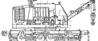
The crane is based on a welded frame equipped with 2 bridges. The front steering axle is mounted on a balancer, which improves wheel traction on uneven roads. Changing the wheel alignment angle is performed by hydraulic power cylinders. The rear axle has a rigid suspension. A 2-speed manual transmission is mounted in the center of the frame. Cardan shafts are used to transmit torque to the axles. Axle gearboxes include spur and bevel gears.
On the side beams of the frame there are outriggers equipped with screw jacks. Installation and cleaning of units is carried out using the crane’s hydraulics. The use of supports increases the stability of the machine and increases the load capacity. A rotating platform is installed on the upper surface of the frame, on which all the working components of the machine are mounted. To connect the platform and frame, a 2-row ball ring with a gear ring is used.
The KS 4361A pneumatic wheel crane is equipped with a diesel power plant, including a 75-horsepower naturally aspirated 4-cylinder SMD-14A unit. The engine crankshaft is connected by an elastic coupling to a turbotransformer, which allows you to smoothly regulate the operating speeds of the machine. The pneumatic system compressor is installed separately from the engine. Torque is transmitted using a V-belt transmission. A fan is used to cool the compressor.
The transmission consists of cam and gear couplings equipped with a hydraulic drive. The nodes include rotation and movement mechanisms, respectively. To control the lifting units, a combined system with pneumatic and hydraulic drive is used. The winches are activated by pneumatic chamber couplings; a similar drive is installed on the reversible drive. Stopping and fixing of the drums is carried out by band brakes.
The standard lattice boom of the crane is 10.5 m long; It is possible to install additional extensions with a size of 5 m (up to 3 pcs.). Additionally, a fixed jib is mounted, having a length of 6 m. When using a jib, the length of the boom is limited to 20 m. There is a hinge unit at the base of the boom; a protective stop is installed to prevent tipping onto the platform.
The machine has a torque converter designed to drive the operating mechanisms of the crane.
A design feature is the installation of boom drive drums, a cargo hook and grab equipment on a single shaft.
The operator is placed in a closed metal cabin. The mechanisms are controlled using levers and pedals.
By special order there are cars with an insulated cabin equipped with an autonomous heater. The pneumatic system is equipped with a water vapor separator. The northern version of the crane allows you to perform work at air temperatures from -60°C.
Story
In 1961, at the Odessa Heavy Crane Manufacturing Plant named after. January Uprising (OZTK) the first 10 experimental cranes, developed in the factory design bureau [3] by designers headed by N. A. Yablonsky and A. V. Filonenko, rolled off the assembly line. Starting next year, a new model, subsequently named K-161
, began to be mass-produced - up to 15 units (daily). At the VDNKh exhibition, the crane received a Grand Gold Medal[5].
Crane K-161
received a single-engine mechanical drive, which had a torque converter (model TRE-375).
The crane used an SMD-14A diesel engine with a power of 75 hp. pp., although at first the designers wanted to supply the SMD-7, which was installed on combine harvesters. After some time, the plant mastered the production of the K-161S
- the so-called.
“Northern version”, which did not differ either in design or in economic indicators, but allowed the crane to operate at ambient temperatures down to −60. In 1964, the K-161
began to be simultaneously produced at YuMZ. Since 1971, production of the model at OZTK was stopped, replacing it with the newly created 25-ton crane KS-5363[5].
Since 1975, YuMZ begins production of a new crane model, which has a number of design similarities with the K-161
, the production of which is being phased out at this plant[3].
The new product receives the index KS-4361A
[2].
After some time, the plant mastered the production of a special modification of the KS-4361S
, which can operate at low temperatures.
And after some time, the basic model KS-4361A
began to be produced at the Kamyshin crane plant)[6].
The production of a special modification for work in tropical conditions was also mastered - KS-4361AT
[7].
In addition, the Kamyshin plant produced KS-4362
(or
K-166
), a diesel-electric crane in which a number of improvements were introduced - for example, the length of the main boom was increased (up to 12.5 m), and it was also possible to use tower-boom equipment[6].
Transportation
Inside the construction site, the equipment moves independently, reaching speeds of up to 15 km/h. Movement with a payload mounted on the crane boom is allowed. In this case, the unit is located parallel to the longitudinal axis of the machine; the permissible speed does not exceed 3 km/h.
To deliver equipment to the work site, the method of towing with a rigid coupling is used. Trucks are used as tractors; road train speed is 20 km/h. When relocating, the gearbox is moved to the neutral position, and the hydraulic cylinders installed on the steering axle are turned off. Additionally, the driveshaft, which serves to drive the front axle, is removed.
Delivery over long distances is carried out by rail. Before loading, the wheels are removed from the machine and the boom is disassembled into its component sections. The upper part of the knot is laid on the lower part. Loading is carried out by an assembly crane unit with a lifting capacity of at least 25 tons. If the machine includes additional boom elements, they are transported on another railway platform.
Modifications
- K-161
(aka
KS-4361
),
K-161S
- predecessors of the crane: respectively. for temperate climates (from −40 °C to +40 °C) and northern regions with low temperatures (polar climate, up to −60 °C). - KS-4361A
- basic model (for temperate climates, from −40 °C to +40 °C). - KS-4361S
is a modification for northern regions with low temperatures (polar climate, up to −60 °C)[6]. Metal structures are made of low-alloy steel, and tires and all sealing parts are made of frost-resistant rubber. The control system has protection (special device) against condensate freezing[4]. - KS-4361AT
- modification for tropical climates[7]. - KS-4362
(aka
K-166
) - diesel-electric crane[6].
Can operate in a turret-boom version[8]. Some of its components are unified with KS-4361A
[8]: rotating mechanism, cargo winch mechanisms [9], running gear [8].