The expanding fist has a special profile and is made integral with the shaft, at the outer end of which an adjustment lever is installed. The brake chamber rod is attached to the lever. There is a worm pair inside the lever. The worm is stopped from spontaneous rotation by a lock. The worm gear is mounted on the splines of the expansion knuckle shaft. When the worm rotates, the gear rotates the knuckle shaft, which leads to a change in the gap between the pads and the drum.
Adjusting the brake mechanisms. The need for partial adjustment of the brake is detected by an increase in the output of the brake chamber rod, which should be no more than 40 mm.
Rice. 1. Working brake mechanism of a ZIL-131 car: 1 - support disk; 2 — brake pad; 3 — brake drum; 4 — expansion fist shaft; 5 - lubrication hole plug; 6 - worm gear: 7 - worm; 8 — lever; 9 — brake chamber rod; 10 - body; 11 - cover; 12—diaphragm: 13—spring; 14 — brake chamber bracket; 15 - cover; 16 — bracket for the pad axles; 17 — eccentric axles of the pads
Partial adjustment is made by rotating the shaft of the adjustment lever, while ensuring that the output of the brake chamber rod when pressing the pedal is within 15-25 mm. On the same bridge, the output of the brake chamber rods should be the same. When supplying and releasing air from the brake chambers, the rods must move quickly, without jamming. The wheel, jacked up and spun by hand, should rotate evenly and freely, and when you press the brake pedal, it should stop sharply.
When fully adjusting, you need to bring the eccentrics of the axes closer together and turn the axes with the marks one towards the other. The marks are placed on the outer ends of the axles protruding under the nuts. Apply compressed air to the brake chamber at a pressure of 1.0-1.5 kgf/cm2 and, turning the eccentrics in one direction or another, center the pads, ensuring their tight fit to the drum. The fit of the pads to the drum is checked with a feeler gauge through the window in the brake drum at a distance of 20-30 mm from the ends of the linings. The 0.1 mm thick feeler gauge should not extend across the entire width of the pad. After this, stop the air supply to the brake chamber and turn the worm of the adjusting lever so that the stroke of the rod is 15-25 mm. When fully adjusted, the camshaft bracket nuts must be loosened and tightened again.
The service brake system drive consists of a compressor, a pressure regulator, three air cylinders, a brake valve, a safety valve, six brake chambers, a release valve, a connecting head, an air bleed valve, a pressure gauge, pipelines and hoses.
The compressor is used to create air pressure in the car's pneumatic system. The ZIL-131 car uses a two-cylinder piston compressor with single-stage compression. The compressor is mounted on the right head of the block and is driven by a belt from the engine crankshaft pulley.
The main parts of the compressor are: crankcase with covers; cylinder block; block head, crank mechanism, similar in design to the same engine mechanism; two inlet valves, two discharge valves, unloader.
The compressor is lubricated from the engine lubrication system. Oil is supplied to the rear cover and through the seal through the crankshaft channels to the connecting rod bearings. The remaining rubbing surfaces are lubricated by splashing. The oil drains from the compressor into the engine crankcase.
The compressor is cooled by liquid supplied from the engine cooling system. The liquid is supplied to the compressor block from the water jacket of the engine inlet pipe and drains from the head into the suction cavity of the pump.
Rice. 2. ZIL-131 car compressor: 1 - bottom cover; 2 - piston; 3 - cylinder; 4 - crankcase; 5 - crankshaft; 6 - plunger; 7 — piston pin; 8 — block head; 9 — discharge chamber; 10—discharge valve; 11—valve plug; 12—inlet channel; 13—inlet valve; 14 - rod; 15 — cylinder block; 16 — air supply channel from the regulator; 17 — pressure regulator; 18 - camera; 19 — rocker arm; 20 - seal
The injection air is supplied from the engine air cleaner to the block chamber where the unloading device is installed. Compressed air is discharged into air cylinders from the block head.
The unloading device is designed to switch the compressor to idle when the pressure in the system increases to 7.3-7.7 kgf/cm2 and put it into operation when the pressure in the system decreases to 6.0-6.4 kgf/cm2. It consists of two plungers with o-rings and rods, a rocker arm with a spring. Compressed air from a pressure regulator can be supplied under the plungers through a channel.
The tension of the compressor drive belt is adjusted by moving the compressor itself relative to the support bracket using an adjusting bolt. First you need to loosen the nuts securing the bottom cover to the support bracket. The belt should be tensioned so that its deflection in the middle of the branch from a force of 4 kgf is 5-8 mm.
The pressure regulator is used to automatically disconnect the compressor from supplying air to the pneumatic system if the pressure in it rises above 7.3-7.7 kgf/cm2 and to turn on the compressor to supply air to the system if the pressure in it drops below 6.0-6 .4 kgf/cm2. The regulator is installed on the compressor cylinder block and consists of a housing with a protective casing, an inlet ball valve with a seat, an outlet ball valve 6 with a seat, two thrust balls with a spring, a rod, an adjusting cap 3, and two filters. The cavity under the exhaust valve is connected to the vehicle's pneumatic system; the cavity where the ball valves are installed is connected by an internal channel to the sub-plunger space of the compressor unloading device, and by a side drilling to the atmosphere.
Rice. 3. Pressure regulator: 1 - casing; 2 - spring; 3 - cap; 4 - rod; 5 — exhaust valve seat; 6 — exhaust valve; 7 — inlet valve; 8, 9 — mesh filters; 10 - body; 11 — bracket
When the pressure in the system is less than 7.3-7.7 kgf/cm2, the inlet and outlet valves are lowered down under the action of a spring, so that the first of them is pressed against its seat, and the second moves away from the seat and through a side hole connects the sub-plunger space of the compressor unloading device with atmosphere.
The compressor unloader plungers are lowered down and their rods do not act on the inlet valves. When the pressure in the system reaches 7.3-7.7 kgf/cm2, the balls of both valves rise, the exhaust valve sits on its seat, and the intake valve opens. Compressed air from the pneumatic system passes through the channel under the plungers of the unloading device, lifts them and opens both inlet channels. The compressor goes to idle, pumping air from one cylinder to another. When the pressure drops below 6.0-6.4 kgf/cm2, the inlet valve sits in its seat, the outlet valve opens, and the compressed air from the sub-plunger space of the compressor escapes into the atmosphere, the compressor is put back into operation.
The regulator is adjusted as follows. By rotating the cap, it is ensured that the compressor starts working at a pressure of 6.0-6.4 kgf/cm2. By changing the number of gaskets between the intake and exhaust valve seats, a pressure of 7.3-7.7 kgf/cm2 is established, at which the compressor is turned off. Only qualified personnel are allowed to open and adjust the regulator.
Air cylinders are used to store a supply of compressed air. Each of the three cylinders is attached with clamps to the frame side members. The cylinders are connected to each other in series. Each cylinder has a valve for draining condensate.
The brake valve is designed to supply compressed air from air cylinders to the brake chambers of the vehicle and to release compressed air from the connecting line of the trailer into the atmosphere in proportion to the pressure on the pedal. In the intervals between braking, compressed air from the vehicle's pneumatic system is supplied through a tap to the trailer's air cylinders.
The brake valve is two-section, diaphragm, with rubber conical valves; The upper section controls the trailer brakes, the lower section controls the vehicle brakes. The crane is installed on the left side member of the frame under the cabin, and is activated by the brake pedal.
The main parts of the valve: a body with two covers, a lever body with a cover, two diaphragms with guide cups and exhaust valve seats, an upper section rod with a guide, a balancing spring, a lower section rod with a balancing spring, a lower section diaphragm return spring, two levers, a lever manual valve drive, two inlet and two outlet valves. Compressed air is supplied from air cylinders through plugs to the central openings of the covers, from the side opening of the upper section cover the air passes to the trailer connecting line, from the side opening of the lower section cover it goes to the vehicle's brake chambers. The cavities inside the housing to the left of the diaphragms are connected to each other and to the atmosphere through a valve.
Rice. 4. Brake valve of the ZIL-131 car: 1 - rod of the lower section; 2 — lever body; 3, 4 - small and large levers; 5 — guide rod of the upper section; 6 — rod of the upper section; 7 — manual drive lever shaft; 8 - traction; 9 — manual drive lever; 10 — valve body, 11 — balancing spring, 12. 22 — diaphragms; 13, 23 – exhaust valve seats; 14 – exhaust valves; 15, 19 — intake valves; 16, 21 — valve body covers; 17. 24 — guide cups; 18 — diaphragm spring of the lower section; 25 - balancing spring of the lower section. 25 - atmospheric valve;
Rice. 5. Safety valve: 1 - seat; 2 - body; 3 — guide rod cracker; 4 - spring; 5 - lock nut; 6 — guide rod; 7 - adjusting screw; 5 - valve; a - hole
The safety valve serves to protect the system from excessive pressure increase in the event of a malfunction of the pressure regulator. The ball valve is installed on the first air cylinder. It consists of a body, a seat, a spring, an adjusting screw with a lock nut. The valve opens at a pressure of 9.0-9.5 kgf/cm2, releasing air from the pneumatic system into the atmosphere.
The disconnect valve is designed to disconnect the vehicle's brake system from the trailer's pneumatic system. The valve is installed at the rear end of the left frame side member and consists of a housing with a cover, a rod with a diaphragm and a spring, a rubber valve with a spring, and a handle with a pusher. When the handle is along the body, the rod rests against the valve and opens it. When the handle is installed across the body, the diaphragm together with the rod rises under the action of the spring and air pressure, the valve closes, and the vehicle’s braking system is disconnected from the trailer’s pneumatic system.
Rice. 6. Isolation valve: 1 - plug; 2 - body; 3 — valve spring; 4 - valve; 5 — diaphragm spring; 6 — rod with diaphragm; 7 - cover; 8 — pusher; 9 - handle
The connecting head is used to connect the car's pneumatic system with the trailer's pneumatic system. The head is installed on the rear cross member of the frame and consists of a body with a cover, a valve with a spring, and a sealing gasket. When driving without a trailer, the valve is closed and the lid must also be closed. When the trailer brake line is connected, the valve opens, allowing compressed air to enter the trailer brake system.
The air bleed valve is designed to bleed compressed air for external needs and is located on the front air cylinder.
Brake chambers are used to convert compressed air pressure into the force required to press the brake pads against the drum. The cameras are installed on the brackets of the brake expansion cam shafts. Each chamber consists of a housing with a cover, a rubber diaphragm, a rod with a fork, two springs, and a sealing washer.
The pressure gauge is used to monitor air pressure in the pneumatic system. The pressure gauge is two-pointer, installed in the cockpit. The top arrow shows the air pressure in the air cylinders, the bottom arrow shows the air pressure in the brake chambers during braking.
The brake system of a trailer operating in conjunction with a vehicle consists of brake mechanisms according to the number of wheels, an air tank, an air distributor, brake chambers, a brake release valve and pipelines. The wheel brake mechanisms, brake chambers, and air tank have the same structure as on a towing vehicle.
Rice. 7. Connecting head: 1 - body: 2 - spring: 3 - valve; 4 — sealing gasket; 5 - cover; 6 - ring nut
Rice. 8. Trailer braking system: 1— air tank; 2— valve for draining condensate; 3 - rod; 4 — exhaust valve: 5 — air distributor housing; 6, 11 — housing covers; 7 — connecting head; 8 — brake release valve; 9 — cuff; 10 — inlet valve; 12 — brake chamber; 13— adjustment lever; 14 — brake mechanism
The air distributor controls the trailer brakes; it is installed on a trailer. Its main parts are: body with covers, cuff with rod, inlet valve, outlet valve. The intake valve seat is the edges of the hole made in the body partition; The exhaust valve seat is a rubber ring sandwiched between the body and the bottom cover. Both valves are mounted on the same stem.
The space inside the distributor is divided into cavities. The cavity above the cuff is connected to the car's brake system, under the cuff - to the trailer's air cylinder, the cavity under the body partition is connected to the trailer's brake chambers, and the cavity under the exhaust valve - to the atmosphere.
Operation of the brake valve in conjunction with the trailer air distributor. When the brake pedal is released, under the action of a balancing spring, the parts of the upper section of the valve are shifted back, the inlet valve of this section is open, and the outlet valve is closed. In the lower section, under the action of a spring, the diaphragm is shifted forward, the inlet valve is closed, and the outlet valve is open. Compressed air from the vehicle's cylinders passes through the open inlet valve of the upper section into the connecting line to the trailer and enters the upper cavity of the air distributor, where it presses on the cuff and lowers it together with the rod down. The inlet valve of the air distributor is closed, the outlet valve is open, i.e., the brake chambers of the trailer are connected to the atmosphere. Compressed air, bending around the edges of the rubber cuff, fills the middle cavity and passes into the trailer's air tank. When the air pressure in the trailer cylinder, and therefore in the connecting line and in the space to the right of the diaphragm of the upper section of the valve, reaches a value of 4.8-5.3 kgf/cm2, the diaphragm bends, compressing the balancing spring, and the inlet valve of this section closes, allowing air to enter into the trailer cylinder stops.
In the lower section of the faucet, the inlet valve is closed and the outlet valve is open; The car's brake chambers are connected to the atmosphere. The car and trailer are unbraked.
When the pedal is pressed, the driver's force is transmitted to the section rods. The rod of the upper section moves forward, the diaphragm of this section also moves forward under the influence of compressed air pressure, the inlet valve closes (or remains closed), and the exhaust valve opens. Compressed air from the connecting line and the upper cavity of the air distributor escapes into the atmosphere, the cuff of the air distributor together with the rod rises up, the exhaust valve closes, and the intake valve opens. Compressed air from the trailer's cylinders enters its brake chambers, which leads to the trailer's braking,
In the lower section of the valve, the rod and diaphragm move back, the outlet valve closes, and the inlet valve opens. Compressed air from the car's cylinders enters its brake chambers, which leads to braking of the car.
Rice. 9. Diagram of the operation of the brake drive of a car and trailer:
When the pedal is released, the exhaust valve in the upper section closes and the inlet valve opens. Air from the car's cylinders enters the connecting line to the trailer's air distributor, where it lowers the cuff with the rod down, closing the inlet valve and opening the outlet. Compressed air from the trailer's brake chambers escapes into the atmosphere.
In the lower section of the valve, the inlet valve closes, the outlet valve opens, and the compressed air from the car’s brake chambers escapes into the atmosphere. The car and trailer are released.
The brake valve has a follower effect. If the driver does not press the pedal all the way when braking, but stops it in an intermediate position, then in the lower section of the valve, after a certain increase in pressure, the diaphragm will bend forward and the intake valve will close. A pressure proportional to the pressure on the pedal will be established in the car's brake chambers. Similarly, in the upper section of the valve, the air will partially escape into the atmosphere; under the action of the balancing spring, the diaphragm will bend back, the exhaust valve will close, and a pressure will be established in the connecting line of the trailer, and therefore in its brake chambers, proportional to the pressure on the pedal. Thus, the brake valve allows you to brake with the efficiency corresponding to the pressure on the pedal.
When braking with the parking brake, the driver's force is transmitted through the drive rods to the lever, which actuates only the upper section of the crane, which leads to braking of the trailer.
The free play of the brake pedal should be 40-60 mm, the upper end of the pedal should not reach the floor by 10-20 mm. The free play of the pedal is regulated by changing the length of the rod connecting the brake pedal to the brake valve by screwing or unscrewing its fork. The air pressure in the trailer connecting line is adjusted by rotating the guide 5 of the rod 6 of the upper section of the valve with the lever housing removed and the guide locknut loosened. The pressure in the trailer connecting line should be 4.8-5.3 kgf/cm2 when the brake pedal is released. The pressure is checked by attaching a pressure gauge to the connection head.
The ZIL-130 car has a working brake system with four brake mechanisms and a pneumatic drive. The design of the brake mechanisms and pneumatic drive devices is in many ways similar to the ZIL-131 car. The main differences are as follows. For the brake mechanisms of the rear wheels, the expansion cam is made along a curved profile, and rollers are installed at the ends of the pads interacting with the cam. When adjusting the brake mechanisms, ensure that the output of the brake chamber rods is within 15-25 mm for the front brakes and 20-30 mm for the rear ones.
The pneumatic drive has two air cylinders; on vehicles not intended for use with a trailer (ZIL-130D1 chassis for a dump truck), a single brake valve is installed, similar to the lower section of a two-section valve. These same vehicles do not have a disconnect valve and a connecting head.
Latest abstracts of the section
- Passenger car depot project with the development of an automatic coupling control point
- Highway design
- Design of the MAZ motor transport enterprise
- Production and technical base of automobile transport enterprises
- Calculation of the lifting mechanism of a dump truck
- Auto-locking systems
- Improving the organization of traffic and reducing the accident rate of public transport in the city of Vitebsk
Copyright © 2010-2022 — www.refsru.com — abstracts, coursework and dissertations
Compressor care
Periodically it is necessary to check the tension of the nuts, the fastening of the compressor to the engine head, the fastening of the pulley, the tension of the drive belt, and the tightness of the nuts of the studs securing the head.
The nuts of the studs securing the head should be tightened evenly, in two steps, in the order shown in Fig. 2. The final tensioning torque should be in the range of 1.2-1.7 kg/m after 80,000-100,000 km, combined with seasonal maintenance (spring), the compressor head must be removed to clean the pistons, valves, seats, springs, air channels, as well as to check the operation and tightness of the valves and plungers of the unloading device.
Valves that do not provide tightness must be ground into the seats, and heavily worn or damaged ones must be replaced with new ones. New valves should also be ground to the seats until continuous annular contact is achieved when tested "for paint". It is necessary to check the condition of the sealing rings of the plungers 26 (Fig. 1) of the unloading device and, if necessary, replace the rings.
In this case, the following order must be observed:
1. Start the engine and increase the pressure in the pneumatic system to 7.0–7.4 kg/cm².
H. Remove the rubber hose connecting the engine air filter to the compressor. If the unloading device is leaking, a characteristic noise of air flowing through will be heard in the air supply pipe to the compressor, and a slight drop in pressure will be noted on the pressure gauge of the pneumatic system.
4. Reduce the air pressure in the pneumatic system to 5.6-6.0 kg/cm² while the plungers will be lowered.
5. Remove the air supply pipe, take out the spring and rocker arm, then lift the rod socket and remove it together with the rod, after which, remove the plunger from its socket with a wire hook, inserting it into a hole with a diameter of 2.5 mm at the end of the plunger or bringing in a compressed air into the horizontal channel of the cylinder block unloader.
6. Replace worn rubber sealing rings on the plungers. Before installation, plungers with sealing rings should be lubricated with engine oil.
Signs of a compressor malfunction are the appearance of noise and knocking in it, an increased amount of oil in the condensate drained from the air cylinders.
Increased oil content in the condensate is usually a consequence of wear on the piston rings, the oil seal at the rear end of the crankshaft, the lower end bearings of the connecting rods, or tarring of the oil drain pipe from the compressor.
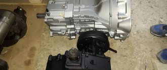
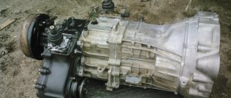
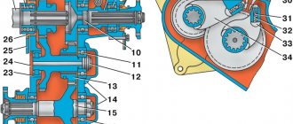
Handbrake zil 131 device
Handbrake of ZIL-130 and ZIL-131 cars
On ZIL-130 and ZIL-131 vehicles, a drum-type central hand brake with two shoes located inside the drum is used.
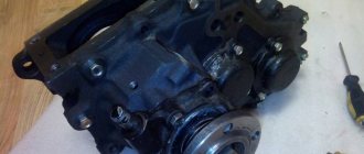
On a ZIL-130 car, the handbrake (Fig. 55, a) is installed on the bearing cover of the gearbox driven shaft, while the cover is both a handbrake bracket and a speedometer gear housing. The drum with a flange is secured to the splines of the driven shaft of the gearbox. On a ZIL-131 car, the handbrake (Fig. 55, b) is installed on the transfer case cover, and the drum with a flange is installed on the splines of the driven shaft of the transfer case.
The handbrake on cars (see Fig. 55) is actuated by lever 13 with handle 14, installed on the left side of the gearbox of the ZIL-130 car and on a box-shaped bracket riveted to the second cross member of the frame of the ZIL-131 car; the gear sector 10 is also fixed on the box-shaped bracket. On the ZIL-130 car, the gear sector 10 is fixed on the gearbox and serves to fix the handbrake lever using a rod 12 with a latch 11. At the lower end of the lever 13 of the ZIL-130 car there is an eyelet 5, and on a ZIL-131 car - bracket 15, which serves to connect rod 3 of the manual drive of the combined brake valve for braking the trailer.
At the splined end of the expanding fist 1 there is an adjusting lever 2, to which a rod 8 from the handbrake drive lever is attached. The rod has a threaded fork 6 with a lock nut 7, which serves to change the length of the rod when adjusting the hand brake. In addition, the handbrake can be adjusted by moving the rod pin 8 in the holes of the adjusting lever 2.
The handbrake is adjusted on a cooled brake to reduce the gaps between the shoe linings and the drum that arise due to wear of the linings and the drum. Large gaps are detected by an increase in the stroke of the brake drive lever 13.
The adjustment procedure is as follows: loosen the lock nut 7, disconnect the threaded fork 6 from the bottom of the lever 13,
move the lever 13 of the handbrake drive to the front extreme position until it stops, and changing the length of the rod 8 by rotating the threaded fork 6, achieve such a position that after connecting the rod to the drive lever, the drum is completely braked when moving the drive lever with the latch And back four to six sector 10 teeth, and when the drive lever was moved to the front extreme position, the drum rotated freely without touching the brake pads. If the rod, which is turned to the limit, does not provide braking when moving the lever latch by six sector teeth, then you need to move the rod pin 8 on the ZIL-130 car and the rod pin on the ZIL-131 car into the next hole in the adjusting lever 2, undoing and unscrewing the nut 9, and then tighten the nut again and tighten the cotter pin. After rearranging the pin, adjust the brake in the same way as indicated above.
Adjusting the compressor drive belt tension
The compressor drive belt must be tensioned so that when a force of 4 kg is applied, the deflection of the belt branch located between the compressor and fan pulleys is 5-8 mm. Belt tension should be checked daily.
The tension of the compressor drive belt is adjusted by moving the compressor. To do this, you need to loosen the nuts securing the bottom cover to the bracket and use the adjusting bolt 20 to ensure the required tension. Then you need to tighten the compressor mount and lock the adjusting bolt with a locknut.
Source