Adjusting engine valves on a ZIL 130 car, as on other engines, requires knowledge of four basic rules
- Where is the first cylinder located? Because all visible marks on the pulleys correspond to the position of the piston of the first cylinder at top dead center (TDC).
- In what position of the crankshaft is the piston of the first cylinder at TDC during the compression stroke? In this position, the intake and exhaust valves are closed and the valve clearances are adjusted.
- It is necessary to know the operating order of the cylinders of a particular engine. That is, which next cylinder will start working. To turn the crankshaft and begin adjusting the next cylinder in sequence.
- It is necessary to know at what angle the crankshaft must be turned to bring the piston of the next cylinder to TDC during the compression stroke
These four rules apply to all four-stroke internal combustion engines. Having mastered these points well, you can adjust the valves without the help of specialists.
Setting TDC at the moment of compression
The problem arises when the piston becomes in the correct position to adjust the valves of the first cylinder. The piston must be at TDC during the compression stroke. There is a mark on the crankshaft pulley. It needs to be aligned with the TDC designation on the scale.
Indeed, the piston of the first cylinder will rise to TDC. But it is necessary to make sure that it is in the compression stroke. Because for the full cycle of engine operation from the first to the eighth cylinder. The piston becomes twice at TDC. We are only interested in one of its positions. This position can be determined in several ways.
- If the engine is in working order on the car. You can remove the tip from the spark plug wire going to the first cylinder. And turn the crankshaft with the ignition on. At the moment a spark jumps between the wire and ground. You should place a mark on the pulley with the TDC designation on the scale. The spark will jump before the piston reaches top dead center. And by setting the marks, the piston will move to the desired position.
- You can unscrew the spark plug of the first cylinder and plug the spark plug hole with a paper plug. When cranking the crankshaft, the plug will shoot out. All that remains is to align the mark on the pulley with the TDC mark on the scale. You can simply plug the hole with your finger. When air starts to come out from under it, all you have to do is align the marks. This indicates that compression is forming in the cylinder. Compression begins. Therefore the valves are completely closed.
- Visually, the TDC position is determined by the rocker arms. In the compression position when the piston approaches TDC, the rocker arms are not movable. The valves are closed. In the second position, when the piston approaches TDC, one valve closes. The second one, after passing TDC, begins to open immediately. If the valves are stationary, all that remains is to align the marks.
After the piston of the first cylinder is in the correct position, it is necessary to adjust the valves of the first cylinder.
TRUCKS GAZ, ZIL, KAMAZ, URAL, MAZ, KRAZ
_________________________________________________________________________________________
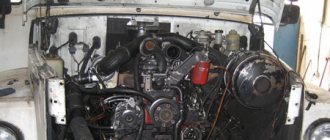
Cylinder head repair and valve adjustment ZIL-130
Checking the fastening of the ZIL-130 cylinder head The ZIL-130 internal combustion engine is equipped with cylinder heads made of aluminum alloy with steel-asbestos gaskets between the heads and the block. Cylinder heads must always be secured with a specified bolt torque. If the cylinder head bolts are incompletely or incorrectly tightened, the tightness of the combustion chamber is compromised and gas breakthrough is possible in those places of the gasket where it is loosely clamped. At the same time, the engine experiences interruptions in operation, unstable operation at low speeds, and starting after the engine is stopped worsens. In addition, if the gasket is damaged, the cooling system fluid enters the cylinders, causing corrosion of the cylinder bore. These reasons lead to loss of power or termination of operation of the ZIL-130 internal combustion engine. Each cylinder head is attached to the engine block with 17 bolts. The bolts should be tightened on a cold engine in two steps - preliminary and final. The final tightening is necessary with a torque wrench, which allows you to control the tightening torque, which should be 7-9 kgm. If you don’t have a torque wrench, you can tighten it with a regular wrench with one hand without jerking. It must be borne in mind that cylinder heads made of aluminum alloy expand when the engine warms up, and therefore the tightening of the block bolts increases; When the engine cools, the opposite occurs. Therefore, at an internal combustion engine temperature of plus 20-25°C, the bolt tightening torque should be closer to the upper limit of 9 kgm, and at an internal combustion engine temperature below minus 5°C, the bolt tightening torque should be closer to the lower limit of 7 kgm. When the ZIL-130 engine is fully warmed up, the tightening of the cylinder head automatically increases to the required limit.
Please note that the four rocker arm axle bolts are also the cylinder head bolts; they should also be tightened. If the heads are tightened, you need to check for possible changes in the gaps between the valves and rocker arms. When changing gaskets, it is necessary to clean all the holes in the cooling jacket in the heads and in the cylinder block. Assembling the ZIL-130 cylinder head with valves. For assembly, use the same stand as for disassembly. The ZIL-130 cylinder head is mounted on a stand and the holes in the bushings and valve seats are blown out with compressed air.
Before installation, the intake and exhaust valve stems and the cylinder head guide bushings are lubricated with oil. The valves should turn smoothly and move in the guide bushings. In case of jamming, select another valve.
Valve spring washers are put on the intake valve bushings, directing them with a flat surface to the cylinder head, and the valve rotation mechanism is placed on the exhaust valve bushings. Then rubber cuffs are put on the intake valves. When installing springs on valves, pay attention to the fact that the coils are located with a smaller pitch towards the cylinder head. Having placed the valve spring plates on the ZIL-130 valve stems, turn the handle of the air distribution valve; in this case, the pressure device of the stand simultaneously compresses all the valve springs. Lubricated with grease, the crackers are installed in the grooves of the valve stems and the pressure device of the stand is raised to its original position. In this case, it is necessary to ensure that the valve crackers fit into the conical holes of the valve spring retainers.
Rotating the cylinder head to a convenient position, screw the studs into the holes of the upper plane, the contact plane of the intake and exhaust pipelines. Adjusting nuts and screws are screwed into the threaded holes of the rocker arms so that their heads are 5-6 mm away from the rocker arms.
Having installed a cotter pin in the holes of the rocker arm axle, put the oil drain chute bracket, washers, valve rocker arm, strut assembly with bushing, spacer spring, etc. on the axle. Place the axle assembly with the rocker arms in the device, compress the spacer springs, insert the cotter pin into the axle hole and install the oil drain chute on the brackets. ICE valves ZIL-130 Valves ZIL-130 are upper, located in the cylinder head in one row, inclined to the cylinder axis, driven from the camshaft through rods, pushers and rocker arms. The valves are made of heat-resistant steel; the angle of the working chamfer of the intake valve seat is 30°, exhaust 45°; The exhaust valve stem has a hole filled with sodium.
To increase their service life, the exhaust valves are forcibly turned during engine operation by a special mechanism. If knocking occurs in the valve mechanism, it is necessary to check and, if necessary, adjust the gaps between the valves and rocker arms, which should be within 0.25-0.3 mm (for intake and exhaust valves). Adjustment of the clearances in the valve mechanism of the ZIL-130 internal combustion engine is carried out on a cold engine using an adjusting screw and locknut located in the short arm of the rocker arm.
To adjust the clearance in the valve mechanism, you need to set the piston of the first cylinder to the top dead center (TDC) of the compression stroke. In this case, the hole on the crankshaft pulley should be located under the “TDC” mark on the ignition timing indicator located on the crankshaft maximum speed limiter sensor. In this position, the clearances of the following valves of the ZIL-130 internal combustion engine are adjusted: - intake and exhaust cylinder 1 - exhaust cylinder 2, intake cylinder 3 - exhaust cylinder 4 - exhaust 5 - intake 7 - intake 8 - g Adjustment of ZIL-130 valves The temperature gap between the valve stem and the toe of the rocker arm gradually changes during operation due to wear of the mating parts of the ZIL-130 timing mechanism and leads to a violation of the adjustment. Therefore, clearances must be periodically checked and adjusted. Increased clearance between the intake valve stem and rocker arm nose reduces valve opening time. This impairs the filling of the cylinder with the combustible mixture, makes it difficult to start the engine, and during its operation leads to a drop in power. An increased exhaust valve clearance leads to poor removal of exhaust gases from the cylinder; engine operation is accompanied by a characteristic metallic knock. Reduced clearance between the valve stem and the toe of the rocker arm leads to a loose fit of the valves in the seat. At the same time, the ZIL-130 internal combustion engine loses compression and overheats, and its power decreases. With a small intake valve clearance, the working mixture during the compression stroke is partially pushed into the intake manifold and then into the carburetor. This phenomenon causes a decrease in the amount of working mixture, lowers the pressure in the cylinder and leads to a drop in engine power. Another sign of a loose intake valve is popping noises in the carburetor, since some of the flammable gases, entering the intake manifold during the working stroke and then into the carburetor, causes ignition of the combustible mixture, which is dangerous in terms of fire. When the clearance at the ZIL-130 exhaust valve is small, this also leads to a drop in power, since during the compression stroke part of the working mixture is removed into the exhaust pipe and then into the muffler. In this case, due to the combustion of the working mixture in the exhaust pipe and in the muffler, popping noises will be heard, accompanied by black smoke coming out of the muffler. Running the engine for a long time with poor valve clearances can lead to premature burning and wear of valve heads, valve seats, warping of valve stems, and wear of the cams. Adjusting valve clearances on a cold ZIL-130 engine at a temperature of 15-20°C in two ways. In the first method, the valves are adjusted separately for each cylinder.
Raise the engine hood, unscrew the nine nuts securing the valve covers with a wrench and remove them, while the cover gaskets do not need to be removed. Then install the piston of the first cylinder in c. m.t. (compression stroke) using an adjusting gear pointer, for which the crankshaft is turned until the mark on the crankshaft pulley aligns with the TDC mark on the pointer (at the end of the second revolution of the crankshaft). When installing the piston in. The radiator lining prevents the alignment of the indicator marks and the crankshaft pulley from being determined.
Therefore, it is recommended to unscrew the spark plug of the first cylinder and remove the distributor cap, which allows you to accurately determine the installation of the piston in the cylinder. m.t. (compression stroke). At the same time, the piston, approaching the c. m.t., will push air out of the cylinder through the spark plug hole, which can be easily felt with a finger applied to the hole; when the piston is in. m.t., then the distributor rotor electrode will be located opposite the terminal of the first cylinder. In this case, both valves, inlet and outlet, of the first cylinder will be closed, and the largest gap will form between the valve stem and the toe of the rocker arm, which is measured with a feeler gauge and, if necessary, adjusted. To adjust the clearance of the ZIL-130 valves, you need to hold the adjustment screw with a screwdriver, loosen the lock nut with a 14X12 mm wrench, then take the feeler gauge with one hand, place it in the gap between the valve stem and the toe of the rocker arm, and with the other hand take the screwdriver and rotate the adjustment screw, setting the required gap, then leave the feeler gauge in the gap and secure the adjusting screw with a lock nut using a wrench and a screwdriver. After adjustment, the gap should be 0.25-0.30 mm for the intake and exhaust valves, and the 0.25 mm feeler gauge should pass freely through the gap, and the 0.30 mm feeler gauge should not pass through it. To adjust the gap in the ZIL-130 valves of the remaining seven cylinders, you need to turn the crankshaft with a handle, and adjust the gaps sequentially according to the operating order of the cylinders 1-5-4-2-6-3-7-8. If the valves are adjusted on an engine removed from the car, or with the radiator removed from the car, then in order to rotate the crankshaft 4 turns, you need to put chalk marks on the crankshaft pulley, placing them at an angle of 90° with the piston of the first cylinder in the crank position. m.t. (compression stroke). The clearances of the remaining valves are adjusted after turning the crankshaft 360° (full rotation). Prolonged operation of the engine with incorrect clearances can lead to premature wear of valve mechanism parts, burning of valves, wear of rocker arms, bearing surfaces of pushrods and camshaft cams. During any disassembly of the ZIL-130 internal combustion engine, which has traveled more than 70 thousand km, it is necessary to check the condition of the return springs and balls of the mechanism for turning the exhaust valve.
If signs of wear are found on the coils of the spring, the spring must be turned with the worn area down. When assembling the mechanism for turning the valve, you need to pay attention to the correct installation of balls and springs; the springs must be located behind the ball relative to the selected direction of rotation. Valve pushers are steel, hollow. To increase the reliability of the cam-pusher pair, special cast iron is melted onto the end of the pusher. There are holes drilled in the bottom of the pusher for lubrication. The intake pipeline is made of aluminum alloy, common to both rows of cylinders, located between the cylinder heads and equipped with a liquid cavity for heating the mixture. The tightening torque of the nuts securing the intake manifold to the cylinder head should be within 15-20 Nm (1.5-2 kg/cm).
The nuts must be tightened evenly, sequentially, crosswise. Exhaust gas pipelines are cast iron, one G on each side of the block. Cover of the timing gears of the ZIL-130 timing gear The cover of the ZIL-130 timing gears is made of AL-4 aluminum alloy. It not only covers the timing gears, but is also the front engine support, which bears significant loads. The cover of the timing gears of the ZIL-130 gas distribution mechanism is rejected if there are chips. Cracks on the surface of the cover, passing close to the oil seal holes and the crankshaft maximum speed limit sensor, are welded. Having secured the lid in a bench vice, drill the ends of the crack and use a grinding wheel to process the crack to a depth of 2-3 mm at an angle of 90°.
The cover is heated in an electric oven to a temperature of 160-190 ° C and the surface prepared for welding is thoroughly cleaned with a metal brush. After cleaning the welded surface with a metal brush, in order to avoid corrosion from slag residues, the lid is washed in water at a temperature of 40-50 ° C. The seam should be smooth, without cavities and slag inclusions, the seam height is recommended no more than 0.5-1.0 mm . Cracks on the surface of the cover in places that bear minor loads are sealed with epoxy paste. An oil seal hole that is worn out beyond the acceptable size is fused, having previously bored it out on a lathe. To secure the ZIL-130 timing gear cover on the machine, use a device consisting of a faceplate to which a support plate is bolted. The timing gear cover is installed on the pins of the faceplate support plate and secured with clamps. The oil seal hole with a diameter of 93+0.1 mm is bored “as clean”, but no more than a diameter of 95.0 mm to a depth of 10.0+0.5 mm.
For surfacing the oil seal hole of the timing gear cover, use the device shown in Fig. 13. The part is placed on two fingers and rotated to any convenient position during the welding process. After surfacing, the holes are cleaned and the quality of the weld is checked. The seam must be smooth, without cavities and slag inclusions. A hole for the bushings that is worn out beyond the acceptable size is repaired by drilling out the hole in the timing gear cover to a diameter of 19.60. A bushing of repair size is pressed into the restored hole and deployed. Rice. 13. Device for surfacing the oil seal hole in the timing gear cover ZIL-130 1 - stand; 2 — retainer ball; 3 — clamp spring; 4 - plug; 5—flange; 6 - finger; 7 - timing gear cover The fastening bolts of the gear cover of the ZIL-130 gas distribution mechanism carry significant loads, and therefore the surfaces of the cover flange under the head of the bolts wear out. The worn surface of the cover flange is machined “as clean”, maintaining the height of the bosses at least 11.0 mm. If the amount of wear on the surface of the cover flange is significant and it is not possible to ensure a boss height of more than 11.0 mm during machining, the worn flange is welded up to 14 mm. If no more than two threads break, thread M6 class. 2 in the mounting hole of the crankshaft maximum speed limit sensor is driven with a tap. If a thread breaks, more than two threads are cut to a repair size. To do this, the timing gear cover is fixed on the drilling machine table, using the mating plane as the base surface, and the worn threaded hole is drilled out to a diameter of 6.7 mm to a depth of 21.0 mm. An M8 thread is cut into the drilled hole. 2 repair sizes to a depth of 16.0 mm. When warping exceeds the permissible size, the mating plane of the timing gear cover of the ZIL-130 timing mechanism is milled “as cleanly” on a vertical milling machine. The thickness of the cover flange after processing must be at least 6.3 mm. When checking the machining accuracy, a 0.02 mm thick feeler gauge should not pass between the test plate and the mating plane of the timing gear cover.
_________________________________________________________________________________________
- GAZ-3307 clutch maintenance
- Steering system GAZ-3307
- Gearbox parts for GAZ-3307
- Maintenance of the rear axle GAZ-3307
- Maintenance of the fuel system of the D-245 diesel engine
- Clutch GAZ-3309 with a diesel engine
- Operations for disassembling the GAZ-3309 gearbox
- GAZ-3309 front axle service
- Repair of cardan shafts of GAZ-3309 cars
_________________________________________________________________________________________
_________________________________________________________________________________________
- Operations for assembling basic components of the ZIL-130 engine
- Service and repair operations for the ZIL-130 gearbox
- Maintenance and repair of ZIL-130 clutch
- Repair and adjustment of the rear axle ZIL-130
_________________________________________________________________________________________
- KAMAZ-4310, 43118, 43114
- KAMAZ-5320, 55111, 53212, 5511, 55102
- KAMAZ-65115, 6520, 65117
- KAMAZ-4308
- Engine KAMAZ-740
_________________________________________________________________________________________
- Parts of the cylinder block and head of the YaMZ-236 engine
- Service maintenance of the YaMZ-236 piston group and crankshaft
- Diagnostics and technical adjustments of the YaMZ-236 engine
- Design and adjustment of fuel injection pump and injectors of the YaMZ-236 engine
- Cylinder block and piston YaMZ-238
- Components of the YaMZ-238 diesel fuel supply system
- Design and adjustment of the fuel injection pump of the YaMZ-238 diesel engine
- Technical design of the YaMZ-239 gearbox
_________________________________________________________________________________________
- Components of the front axle and steering rods of the Maz-5516, 5440
- Steering system of Maz-5516, 5440 cars
- Clutch and gearbox parts Maz-5516, 5440
- Maintenance of drive axles of MAZ-5516, 5440 vehicles
- Power steering for Maz-5551, 5335 cars
- Maintenance of cardan transmission of Maz-5551, 5335 cars
- Maintenance and adjustment of clutch MAZ-5551, 5335
- Repair and service of the rear axle of MAZ-5551, 5335 cars
_________________________________________________________________________________________
- Gearbox Ural-4320
- Construction and adjustment of Ural-4320 bridges
- Maintenance of transfer case Ural-4320
- Steering components Ural-4320
_________________________________________________________________________________________
- Servicing the KRAZ-255, 260 gearbox
- Steering mechanism and power steering Kraz-255, 260
- Adjustments and repairs of the power steering cylinder and steering rods of the Kraz car
- Drive axle components and drive shafts Kraz-255, 260
Adjusting valves ZIL 130
To adjust the valves, you need to loosen the lock nuts of the adjusting screw. A probe with a thickness of 0.25 or 0.3 mm is installed between the valve and the rocker arm. If a 0.25 mm probe is installed. That is when you tighten the adjusting screw. The rocker arm clamps the dipstick. The probe should move with little effort. If a probe with a thickness of 0.3 mm is installed, the force must be stronger. The dipstick moves but the rocker arm should not put pressure on the valve, otherwise it will open and the adjustment will not be correct. Valve adjustment on a ZIL 130 car provides for equal clearances on the intake and exhaust valves. After adjustment, the lock nuts must be tightened. In this case, the adjusting screw must not be allowed to turn. Therefore, when tightening, it must be held with a screwdriver.
Gas distribution mechanisms
They manifest themselves in a decrease in engine power, uneven operation, increased fuel consumption, and valve knocking.
The engine does not develop full power if the adjustment of the thermal clearances in the gas distribution mechanism is not correct, or if the valves do not fit tightly to their seats.
An increase in clearances in the valve drive causes an increase in shock loads on the seat-valve interface. Reducing the clearances as a result of incorrect adjustments or carbon deposits leads to incomplete seating of the valves in the seat and a violation of the tightness of the cylinders, which manifests itself in increased valve knocking.
If the cylinders are significantly leaky, the pressure at the end of the compression stroke and during the expansion stroke is greatly reduced, which increases fuel consumption, reduces engine power, makes it difficult to start and leads to uneven operation. Uneven engine operation can also occur due to loss of elasticity or breakage of the springs of the gas distribution mechanism, sticking of valves in the guide bushings, wear of the camshaft gears, pushers, guide bushings and rocker arm axles. In ZIL-130 and ZIL-645 engines, the balls and springs of the valve rotation mechanism may become stuck.
During the operation of passenger cars, due to wear and stretching of the belt, wear of the hinge joints of the chain links and other parts of the camshaft drive, the belt or chain elongates, which causes vibration, significant noise and a decrease in engine power.
Gas distribution mechanisms Maintenance
Every day, after warming up the engine, you need to make sure by ear that there are no knocking noises at different crankshaft speeds.
During TO-1 , listen to the operation of the valve mechanism and, if necessary, adjust the gaps between the valves and rocker arms. During TO-2, the fastening of the timing gear cover is checked and, if necessary, tightened.
On VAZ engines, after the first 2,000 km, and then after 30,000 km, it is necessary to tighten the camshaft bearing housing nuts. On passenger car engines, after 15,000 km, you need to check the condition and degree of tension of the camshaft drive belt or chain and tighten them.
If there are folds, cracks, delamination and fraying of the drive belt, there is a danger of rupture when the engine is running, so it must be replaced earlier than the specified period (60,000 km). If the belt becomes oily, wipe it thoroughly with a rag moistened with gasoline.
On a Moskvich-2140 car, to prevent premature wear and reduce noise of the camshaft chain drive, it is necessary to carry out its first two tightenings every 5,000 km, and the subsequent ones every 10,000 km.
The thermal clearances of the valves are checked and adjusted after every 30,000 km, and if necessary, in a shorter period of time.
Gas distribution mechanisms
Troubleshooting methods
The technical condition of the gas distribution mechanism is assessed by the presence and nature of knocks, valve tightness, elasticity of valve springs and changes in pressure in the intake and exhaust pipelines.
If at idle speed at a low crankshaft speed you hear a knocking sound at the locations of the valve bushings, this indicates a lean combustible mixture and sticking of the intake valves. Frequent knocking, merging into a general noise, is typical when the timing gears are worn out and their teeth may break.
By increasing the crankshaft speed, listen to the engine at the locations of the camshaft bearings. An even knock of a medium tone, similar in nature to the knock of connecting rod bearings of the crankshaft, indicates increased wear of the bearings and journals of the camshaft.
A sharp knock in all engine operating modes in the area of the rocker arms with a simultaneous drop in engine power and its operation intermittently indicates an increase in the gaps between the rocker arms and the ends of the valve stems.
The tightness of the valves is determined simultaneously with measurements of the tightness of the cylinders using compression meters, a K-69M device, and a gas flow meter. Leaking valves may be one of the reasons for decreased compression.
To check the elasticity of valve springs without disassembling the valve mechanism, use the KI-723 device (Fig. 21). After removing the valve mechanism covers, install the legs 5 of the device
Measuring the elasticity of valve springs with the KI-723 device:
1 - handle, 2 - rod, 3 - ring, 4 - body, 5 - legs of the device.
On the spring plate, move ring 3 to the uppermost position and press handle 1 with such force that the spring settles by 0.5-1 mm. After removing the device, determine the compression force based on its readings and repeat the measurement. If the force is less than the maximum, it is necessary to replace the spring or place a gasket under it.
The order of operation of the ZIL 130 engine cylinders
To adjust subsequent valves, you must know the operating order of the cylinders. He's next
That is, after adjusting the first cylinder, you should adjust the valves of cylinder 5, then 4, and so on in order.
Cranking the crankshaft
In order to bring the cylinder pistons to TDC one after another in order, it is necessary to rotate the crankshaft at the same angle each time. This angle is
90 degrees.
So as not to make a mistake. you can apply markings on the pulley yourself
And turn the crankshaft according to your marks
You can simply unscrew all the spark plugs and move the piston of each cylinder to TDC by touch using a screwdriver.
The rotation looks like this: The valves of the first cylinder are adjusted when the mark on the pulley and the scale are aligned. Next, the crankshaft is rotated clockwise 90 degrees and the valves of cylinder 5 are adjusted. Then the crankshaft is rotated 90 degrees. The valves of cylinder 4 and so on up to cylinder 8 are adjusted. According to the operating order of the cylinders. You can easily understand why the crankshaft rotates 90 degrees.
During one engine cycle, from the first to the eighth cylinder, the crankshaft rotates twice. The camshaft makes one revolution. Two revolutions of the crankshaft are 720 degrees, two times 360. There are 8 cylinders in operation. So, we divide 720 by 8 and we get 90 degrees.
If there were 6 cylinders, then divide 720 by 6 to get 120 degrees; four-cylinder engines are rotated 180 degrees to adjust the valves.