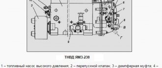
Operations for disassembling and installing the fuel injection pump YaMZ-236
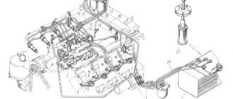
To adjust the fuel injection advance angle of the YaMZ-236 diesel engine of the Ural, Maz, and T-150 tractors, two hatches are provided on the flywheel housing (see Fig. 1), and the angle values are marked in two places on the flywheel.
For the lower indicator 3, these values are made on the flywheel in digital terms, and for the side indicator 4 - in alphabetic expression, while the letter “A” corresponds to the value in digital terms of 20°; letter “B” -15°; letter “B” -10°; letter "G" -5°.
Rice. 1 — Combining the marks on the YaMZ-236 flywheel with the flywheel housing indicators
1 – flywheel housing; 2 – flywheel; 3, 4 – flywheel housing indicators; 5 – top hatch plug; A – direction of rotation of the crankshaft
Rotate the crankshaft of the YaMZ-236 engine of the Ural, Maz, and T-150 tractors clockwise (as viewed from the fan side) until the marks on the crankshaft pulley and the timing gear cover align.
Or on the flywheel with a pointer corresponding to the installation advance angle of fuel injection YaMZ-236N, B: 15º+1º - on engines equipped with a V-shaped injection pump, the installation angle of advance of fuel injection is 10º...11º.
In this case, the valves in the 1st cylinder must be closed. You can rotate the crankshaft with a wrench using the crankshaft pulley mounting bolt or a crowbar using the holes in the flywheel with the flywheel housing hatch cover removed.
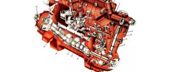
When the marks are aligned, mark “A” on the end of the coupling (Fig. 2) should align with mark “B” on the indicator. If the marks are not aligned, adjustments must be made.
Rice. 2 — Clutch for driving the fuel pump of YaMZ-236 N, B, NE, BE engines
1 – drive shaft; 2 – drive plates; 3 – driving coupling half; 4 – bolts; 5 – terminal connection bolt; 6 – bolts; 7 – driven coupling half; 8 – fuel injection advance clutch; 9 – high pressure fuel pump; A – mark on the coupling; B – mark on the index
The procedure for adjusting the injection advance angle of YaMZ-236N, B, NE, BE engines:
— check the tightness of the coupling half 3 on the drive shaft 1 and the tightening of the terminal bolt 5 (tightening torque 43.2...58.9 Nm (4.4...6 kg/cm)); — unscrew (loosen) two bolts 4 and by turning the advance clutch, use the oval holes on the flange of the coupling half to align the marks “A” and “B”; — without disrupting the aligned position of the marks, tighten the bolts 4 of the drive with a tightening torque of 43.2...58.9 Nm (4.4...6 kg/cm). In this case, the deviation of the plate package from its position in one plane should be within ±1 mm. Take measurements near the places where the plates are attached; - Rotate the crankshaft and check that the injection timing is set correctly. The discrepancy between the marks should be no more than one division or 1º rotation of the crankshaft.
During TO-2, check the presence of oil in the fuel injection advance clutch of the YaMZ-236 engines of the Ural, Maz, and T-150 tractors and, if necessary, add oil.
To check, install the coupling with the holes in the upper position and remove the plugs. When the clutch is slowly turned 70º, oil should begin to flow out of one hole. After adding oil, tighten the plugs.
Check and adjust the amount and uniformity of fuel supply in the following order:
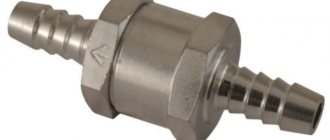
Check the tightness of the discharge valves, for which:
— install a sealed plug on the bypass valve, supply fuel through the inlet channel of the fuel pump at a pressure of 0.1...0.12 MPa (1.0...1.2 kgf/cm2); — when the rack position corresponds to the supply being turned off, fuel leakage from the fittings is not allowed for two minutes. If there is a leak, replace the discharge valve.
Check the opening pressure of the discharge valves of the YaMZ-236 fuel pump, which should be 0.85...1.15 MPa (8.5..11.5 kgf/cm2).
The pressure control of the start of opening of the injection valves is carried out at the moment the fuel begins to move from the fittings of the pump sections with a gradual increase in pressure at the inlet to the fuel pump and the position of the rack corresponding to the supply being turned off and the bypass valve hole being plugged.
If necessary, adjust the valve opening pressure by changing the number of shims. A 0.1 mm thick gasket changes the valve opening pressure by 0.1 MPa. Install a 0.4 mm thick gasket between the spring and the adjusting shims.
Check the fuel pressure in the line at the inlet of the fuel pump of Ural, Maz cars, and T-150 tractors.
The pressure should be 0.075-0.025 MPa (0.75-0.25 kgf/cm2) at a camshaft speed of 1030 min-1 for fuel injection pumps 604.5, 604.5-10 and 980 min-1 for fuel pumps injection pump 607.5, 607.5-10 when the control lever rests on the maximum speed limit bolt. If necessary, unscrew the bypass valve plug and use washers to adjust the opening pressure.
Check the power reserve of the YaMZ-236 injection pump rack. The power reserve of the rack is understood as the free movement of the rack (backlash) in the direction of turning off the feed at 450-500 min-1 and when the governor control lever rests on the bolt for limiting the minimum rotation speed.
If there is no power reserve of the rack, it is necessary to unscrew the power adjustment screw all the way and then use the rocker bolt to adjust the power reserve of the rack within 1-1.5 mm and lock it.
Check the start of turning off the starting fuel supply at 230–250 rpm when the control lever rests on the minimum speed limit bolt when the rack begins to move. If you need to increase the speed, remove the spring hook from the rack lever and screw it into the spring.
To reduce the speed, the hook is turned out. After this, place the hook on the rack lever.
Check the value of the average starting fuel supply, which should be at least 230 mm3/cycle at 80-10 min-1 of the pump camshaft. It is adjusted by the rocker screw only in the direction of increasing the fuel supply. After adjustment, caulk the rocker screw. Check the supply is turned off.
When the governor control lever rests on the maximum speed limitation bolt, check the rotation speed of the pump camshaft - corresponding to the beginning of the rack ejection, determined by the moment the rack begins to move in the direction of turning off the supply.
The start of rack ejection should occur at a rotation speed of (1065-1085) min-1 for the YaMZ-236N, YaMZ-236NE engines and (1025-1045) min-1 for the YaMZ-236B, YaMZ-236BE engines. Adjustment is made with the maximum speed limit bolt.
Check the rotation speed corresponding to the end of the rack ejection, determined by the moment the fuel supply to the injectors stops, when the governor control lever rests on the maximum speed limit bolt. The end of the feed cut-off should occur at a rotation speed of 50-100 rpm higher than the start frequency of the rack selection.
The fuel injection pump of the YaMZ-236 diesel engine of the Ural, Maz, and T-150 tractors is adjusted using a double-arm lever screw.
When the screw is screwed in, the rotational speed of the end of the ejection decreases; when turned out, it increases. At the same time, the start of shutdown also changes, so subsequent checking and adjustment is necessary.
Check the operation of the boost fuel supply corrector as follows:
Wash the mesh filter of the fitting in clean gasoline and blow it thoroughly with compressed air.
Clean the calibrated hole in the corrector body with soft wire with a diameter of (0.5–0.7) mm.
Check the tightness of the membrane cavity. To do this, supply air under a pressure of 0.06-0.01 MPa (0.6-0.1 kgf/cm2) to the hole on the cover 6 of the membrane housing. When the supply air duct is completely blocked, the pressure drop in the membrane cavity over a period of 2 minutes should not exceed 0.01 MPa (0.1 kgf/cm2).
Set the rotation speed of the YaMZ-236 cam shaft to 650-10 min-1, supply oil under pressure of 0.25–0.3 MPa (2.5-3 kgf/cm2) to the corrector, the control lever should be against the maximum limit bolt speed limit.
Adjustment of the cyclic fuel supply value of YaMZ-236 for Ural, Maz vehicles, and T-150 tractors at an excess pressure on the membrane of 0 MPa is performed with the adjusting bolt of the lever. When screwing a bolt in, the feed increases, when turning it out, it decreases. After adjustment, lock the bolt with a nut.
The amount of cyclic fuel supply at intermediate air pressures on the membrane is adjusted by the spring housing. When the spring housing is screwed in, the fuel supply decreases; when turned out, it increases.
After adjustment, secure the spring housing with a nut. Before replacing a worn diaphragm (if necessary), you need to measure the amount of protrusion of the rod from the lower end of the nut at the diaphragm and rod assembly.
After this, replace the membrane and assemble it with the rod with the same amount of rod protrusion with an accuracy of 0.1 mm. When installing the boost corrector after dismantling (if necessary) on the regulator, use the stop lever to move the YaMZ-236 rack to the extreme off position and install the boost corrector into the regulator body, then release the stop lever.
Check the adjustment of the boost corrector and whether the fuel supply is turned off by the regulator.
Check that the cyclic feed is turned off with the stop lever. When turning 40-45 degrees from the original position, the fuel supply from the injectors of all sections of the fuel pump at any speed in any position of the regulator control lever should be completely turned off.
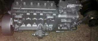
Dismantling and installation of the high pressure fuel pump of YaMZ-236 engines
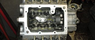
Dismantling the fuel injection pump section YaMZ-236
Rice. 3 — Lever for removing the injection pump pusher plate of the YaMZ-236 diesel engine
1 – lever; 2 – pusher spring; 3 – pusher plate
Disassemble the pump section of the YaMZ-236 injection pump in the following order:
Remove the side cover and rack cap.
Using a special lever (Fig. 42), compress the pusher spring and remove the lower pusher plate.
Remove the locking blocks, unscrew the fittings and remove the seats along with the discharge valves from the pump body with a special puller. To remove, screw the puller mandrel onto the threads of the discharge valve seat until the bushing stops against the pump body.
By turning the eccentric of the puller upward, remove the discharge valve seat.
Unscrew the locking screws of the plunger bushing and remove the plunger pairs from the pump body.
Squeeze slightly and remove the spring from the pump housing along with the upper plate, rotary sleeve and ring gear.
Remove the pusher from the guide in the housing.
Rice. 4 — Installation of a rotary sleeve with a ring gear
Assemble the pump section of the YaMZ-236 fuel injection pump for Ural and Maz vehicles and the T-150 tractor in the reverse order.
When assembling, pay attention to the following:
— the discharge valve with a seat, as well as the plunger pair, are precision pairs, and each of them can only be replaced as a set; - install the rotary sleeve with the ring gear assembly in the middle position of the rack (relative to the pump body) so that the slot of the rim is in the plane of the axis of the hole for the locking screw in the YaMZ-236 pump housing, and the middle tooth of the rim is in the middle cavity on the rack (Fig. 43); — when installing the plunger pair, make sure that the rubber sealing ring is put on the plunger sleeve; the flat at the bottom of the plunger shank should face the bushing retaining screw; — after tightening the locking screw of the plunger bushing, check the mobility of the rack and the amount of its stroke, which must be at least 25 mm; the rail should move easily, without noticeable difficulties; — tighten the fitting to a torque of 100–120 Nm (10–12 kg/cm), after tightening each fitting, check the movement of the rack. After assembly, adjust the fuel pump with the regulator on the bench.
Installation of fuel injection pump on diesel engine YaMZ-236
Install the driven coupling half onto the advance coupling (damper coupling) and secure with bolts.
Turn the injection advance clutch so that the bosses of the driven half-clutch are in a horizontal position and the mark on the end of the clutch is in the pointer area.
Install the coupling half flange assembled with the drive coupling half and plate packs on the drive shaft, while protrusion “a” on the coupling half flange should be on the left side when looking at the drive from the fan side.
Install the YaMZ-236 high-pressure fuel injection pump for Ural, Maz, and T-150 tractors with an advance clutch (with damper) assembly onto the engine and secure it with bolts.
Before tightening the drive pinch bolt and after setting the injection advance angle, adjust the flatness of the plate packs by moving the coupling half flange along the drive shaft.
Install the fuel pump on the engine cylinder block in a vertical position, tighten the fastening bolts evenly, preventing the pump from clogging. The final tightening torque of the pump mounting bolts is 30-40 Nm (3-4 kg/cm).
Connect the sections of the YaMZ-236 diesel pump to the injectors with high-pressure fuel lines.
Adjust the injection advance angle.
Check the presence of oil in the housings of the high-pressure fuel pump and regulator, if necessary, add oil to the level of the hole for the oil drain pipe. Connect the oil inlet and outlet pipes and fuel lines.
After starting the engine, adjust the minimum idle speed of the crankshaft as follows:
Loosen the lock nut and unscrew the buffer spring housing by 2 - 3 mm.
Use the minimum rotation speed limit bolt (the control lever must rest against this bolt) to adjust the minimum idle speed until slight fluctuations in the crankshaft speed of the YaMZ-236 engine appear.
When the bolt is screwed in, the engine speed of Ural, Maz, and T-150 tractors increases, and when screwed out, it decreases.
Screw in the buffer spring housing until the instability of the rotation speed disappears.
It is strictly forbidden to screw in the buffer spring housing until its end aligns with the end of the locknut. After adjustment, secure the minimum speed bolt and the buffer spring housing with nuts.
The minimum idle speed can also be adjusted on a new engine during the initial period of its operation.
All necessary parts can be purchased in our catalog
Ignition adjustment
To carry out adjustments, there are two special hatches in the flywheel housing design. The angle values are indicated on the body of the part. In this case, the bottom column expresses the values in numbers, and the side column – in letters.
The crankshaft rotates only in a clockwise direction. The view is directed from the side of the fan. Rotation can be done using a wrench hooked onto a bolted connection. The crankcase cover must be removed.
During the process of aligning the marks, the letter “A” printed on the end of the coupling must align with the mark “B” on the lower indicator. If the connection does not occur, then it is necessary to fine-tune the parts.
How to set the advance angle on the YaMZ-238 engine
Setting the advance angle VT depends on the characteristics of each coupling individually, and the selection of the advance clamping device at the front end of the housing with numbers 18 and 20.
The UOVT should be set in the following sequence:
- Disconnect the high pressure pipe from the pipe of the 1st section of the injection pump.
- Fix the torque meter (momentoscope) on the pipe of the 1st section.
- Pump fuel with a hand pump into the engine power supply system, having previously unscrewed one of the plugs to bleed air from the injection pump housing.
- It is necessary to pump the system until the leaking fuel stops foaming, then tighten the plug tightly.
- You need to make sure that the fuel supply with the regulator bracket is turned on, and start turning the engine crankshaft to the right until fuel appears in the glass tube (chamber) of the torque meter.
- While continuing to slowly turn the crankshaft, you need to carefully watch the fuel in the glass chamber of the device.
If at the time of the start of fuel movement in the chamber this coincidence of marks is not yet present, you need to:
- unscrew the mounting bolts;
- turn the motor shaft coupling half on the flange in the opposite direction of torsion;
- retighten the mounting bolts;
- check the position of the UOVT again.
When, during the start of fuel movement in the chamber, the marks have already passed the alignment point, you need to:
- Turn the motor shaft coupling half along the thread on the flange;
- the displacement of the coupling by one value unit relative to its flange is equal to 4 divisions on the flywheel or timing gear housing.
Upon completion of the adjustment of the OVT angle, the location of the marks on the drive shaft coupling half and its flange should be changed. The position of the marks must be checked during each maintenance of the YaMZ 238 motor.
Expert advice
It is best to make a torque scope yourself so that the device fits perfectly to the engine. You can create a device from several tubes. During operation, it is necessary to monitor the tightness of the tubes and prevent leaks.
Another important point is the process of pumping diesel fuel until the tube appears in sight. Inflating is done by rotating the shaft. A rise in the fuel mass will be noticeable when the shaft is rotated before directly approaching the elements of the first piston. It is important to rotate the shaft smoothly and very slowly.
With slippery fastenings of the YaMZ 236 m2 fuel injection pump, it is important to rotate it so that the injection of the fuel mass corresponds to the injection designation on the flywheel.
Source
Setting the advance angle
The required advance value is located next to the special mark. The YaMZ 236 fuel injection advance clutch is where this risk is applied. The normal value is 20 or 18 points. The angle of the fuel mass itself is determined by the primary cylinder.
Control is carried out using a conventional pump. So, they work on the power supply system of a car engine, without fail, first opening the valves through which air escapes from the engine. After the air masses have come out without any residue, the plugs are wrapped. Next, you should connect the momentoscope device to the fittings of the special section from the fuel pump. Before carrying out the procedure, it is necessary to remove the injection pump of the Yamz 236 cylinder.
Read also: Volkswagen Polo automatic transmission oil change
The advance is adjusted as follows:
- the bracket from the working power apparatus is transferred to the working state;
- drain all the fuel from the glass container until the volume of liquid reaches the mark in the middle part of the tube;
- carefully turn the crankshaft.
All movements must be made strictly in the direction of torsion. The current position of the meniscus in the tube must be constantly observed and monitored. Its sharp rise signals the start of fuel start-up by a certain section. The line marked on the pulley should be opposite the line with the number marks. The procedure for setting the angle requires special accuracy up to 1 value.