KrAZ transfer case
Some components and mechanisms may look and be placed differently on different models, as a result of which even the general layout of the KrAZ
. So the power take-off can be combined either with the main gearbox or with a transfer case. On many models it is absent altogether, or its functions are performed by the same transfer case.
Other units, with a generally identical purpose and almost identical location, are themselves arranged differently due to the emergence of new design solutions and operating features. The mentioned KrAZ transfer case is just one of them.
In the standard version, the task of this unit is only to distribute torque to different axles of the car. That is, its structure is extremely simple - a crankcase, several shafts with gears and bearings. Kremenchug trucks were one of the first to add a center differential mechanism to the listed parts. The KrAZ 255, 256 transfer case belongs precisely to this experimental category - on them, a similar arrangement of mechanisms has proven itself so well that the question of its further “release to the masses” was simply not raised.
But the question was raised about increasing functionality. The developers were constantly thinking about how they could additionally load the transfer case, and then they remembered about PTOs - power take-offs. As a result, the KrAZ 260 transfer case received a tiny addition, which made it possible to use the engine power not only for the wheels, but also for the operation of the standard winch.
And then everything was simple - modifications, additions and improvements. If it was not possible to replace the PTO, it was simply placed where it was more appropriate. If a separate selection unit was not needed, then it was combined with a “distributor”. In addition to the 260th model, an example of such a combination is the KrAZ 6510 transfer case, which provides for power take-off “in favor” of the platform tipping mechanism.
Such overtime work, especially when it is associated with an increased coefficient of friction, always affects the wear of parts. Our company is ready to offer you components for KrAZ transfer cases of any model and the assembled transfer cases themselves. All offered spare parts are of high quality, have an extended service life and are properly certified by MADI.
TRUCKS GAZ, ZIL, KAMAZ, URAL, MAZ, KRAZ
_________________________________________________________________________________________
Repair work on the Kraz transfer case
Description of the transfer case (transfer case) of KrAZ-256 and KrAZ-256B vehicles, which differs from the transfer case of other KrAZ vehicles by the presence of a power take-off. The following procedure for disassembling the transfer case (transfer case) of Kraz-256 vehicles is recommended:
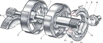
Fig. 15. Transfer case of the Kraz-256 car 1—low gear of the drive shaft; 2—power take-off gear; 3 - top gear of the drive shaft; 4 - drive shaft; 5, 41,45, 57 and 76 - keys; 6, 20, 38, 40, 49, 59, 69 and 72 - bearings; 7 — front crankcase cover; 8, 16, 22, 35, 47, 53 and 70—gaskets; 9 — ball spring plug; 10 - spring; 11 — retaining ball; 12—rod; 13 - fork, 14 and 55 - flanges; 15 — cover of the front bearing of the drive shaft; ;7, 33, 51 and 83 — oil seals; 18, 39, 61, 64, 73, 77 and 84 - support washers; 19, 37, 50 and 60 - retaining rings; 21 — front crankcase; 23 — low gear of the intermediate shaft; 24 — synchronizer; 25 — splined synchronizer bushing; 26 high gear of the intermediate shaft; 27 — front intermediate shaft bushing; 28—washer; 29 — speedometer drive fitting; 30 — adjusting gasket; 67 — driven gear of the speedometer drive; 32 — oil seal cover; 34 — cover of the front bearing of the intermediate shaft; 36 — speedometer drive gear: 42 — middle axle drive shaft; 43 — middle axle drive shaft gear; 44 — front spacer sleeve of the intermediate shaft; 45— differential lock clutch fork lever; 48 — rear housing; 52 — felt sealing ring; 54 - cover; 56—intermediate shaft; 58 — rear bushing of the intermediate shaft; 62 — drive shaft of the middle bridge of the intermediate shaft, 63 — satellite; 65 — differential cage; 66 - spring; 67 — retaining ball; 66—differential lock clutch fork shaft; 71 — cover of the rear bearing of the intermediate shaft; 74 — rear axle drive shaft; 75 — differential crosspiece; 76— drive gear of the rear axle of the intermediate shaft; 79 — rear axle drive shaft gear; 80 — splined bushing for differential lock clutch; 81 — differential lock clutch; 82 - cover; 83 - pin; 86 — differential lock clutch fork; 87— rear crankcase cover
Disconnect the sliding fork of the main intermediate shaft from the flange of the Kraz-256 transfer case, unscrew the nut of the flange securing the propeller shaft to the transfer case, remove flange 14 (Fig. 15) and the flange washer. Remove the flanges 55 of the drive shafts of the middle and rear axles. Unscrew fitting 29 of the speedometer drive, remove shims 30 and driven gear 31 of the speedometer drive. Remove the intermediate handbrake lever shaft bracket. Remove cover 15 of the front bearing of the drive shaft of the Kraz-256 transfer case together with the cushion, covers 34 and 71 of the front and rear bearings of the intermediate shaft and covers 54 of the drive shafts of the middle and rear axles. Unscrew the bearing nuts 38 and 69 of the transfer case intermediate shaft, remove the washers and speedometer drive gear 36. Remove the retaining rings 50 of the rear bearings of the drive shafts of the middle and rear axles of the Kraz-256 and press out the bearings. Unscrew the bolts securing the rear crankcase cover 48 (see Fig. 15) and use the release bolts to separate the cover 87 (it is prohibited to disassemble the rear housing of the KRAZ transfer case with the cover). Two cover mounting bolts can be used as release bolts. Remove the drive shaft of the middle axle and the drive shaft of the rear axle of the Kraz-256. Carefully, so as not to lose the retaining balls, remove the differential lock clutch 81. Remove the retaining balls and use a wire hook to remove the springs of 66 balls. Press the differential using the support washer 77 and the splined sleeve 80 of the differential lock clutch. Remove the keys 57 from the grooves of the intermediate shaft, remove the support washer 73, the middle axle drive gear 62 and the support washer 61. Remove the front crankcase cover 7 (or the power take-off box installed in this place in the transfer case of the KrAZ-256 and KrAZ-256B vehicles) . Remove the retaining ring 19 of the front drive shaft bearing and press out the front drive shaft bearing 20. Push the drive shaft forward and then remove it. Remove the retaining ring 37 of the front bearing of the intermediate shaft of the Kraz-256 transfer case and use the same puller to press out the bearing 38, remove the support washer 39 and the front washer of the low gear. Unscrew the rear housing mounting bolts, remove the cover and use a crowbar to disconnect the rear housing 48. Remove the intermediate shaft of the Kraz-256 transfer case, the synchronizer, the low gear and the rear washer of the low gear. If it is necessary to remove the bearing rings remaining in the crankcases, remove the locking rings and knock out the bearing caps with a drift from inside the crankcases, then remove the bearing rings. To disassemble the Kraz-256 transfer case differential, unscrew the mounting screws of the cage and, turning it, remove it from the crosspiece, remove washers 64 and satellites 63. If necessary, compress the gears from the drive shaft, for which: Press the low gear gear; put a tightening ring on the Kraz-256 power take-off gear, place two half-rings on it so that the inner flanges of the half-rings capture the gear, tighten the half-rings with a ring and, using a puller to grab the outer flanges of the half-rings, compress the power take-off gear. The top gear is compressed in a press. Press spline bushing 25 (see Fig. 15) of the synchronizer from the intermediate shaft, for this purpose: place half rings on the bushing so that the inner shoulders of the half rings fit between the bushing and the end of the top gear hub; put the clamping ring on the half rings and press the bushing together. Remove the synchronizer spline bushing and, having removed the keys 57, remove the top gear 26 with the bushings assembly and the rear washer. Disassemble and remove the drive mechanisms of the differential lock and activation of the Kraz-256 transfer case, for which: - unscrew the locking screws of the differential lock mechanism engagement fork and remove roller 68 of fork 86 with lever 45; — remove covers 82 and 32, oil seals and 33 shafts of the differential lock fork and the transfer fork rod; — unscrew the plug 9 of the retaining ball 11 of the power fork, remove the spring with a wire hook and remove the retaining ball; — unscrew the installation bolt of the switching fork of the Kraz-256 transfer case, remove rod 12 and fork 13 from the crankcase; The wear of the bushing collars of the low and high gear gears of the KrAZ-256 intermediate shaft with bushings pressed into the gear is allowed up to 68.5 mm and up to 123.5 mm, respectively. Reducing the length of the internal tooth of the high and low gears is allowed to a size of 7.5 mm. Wear of the collars of the bushings of the drive gears of the middle and rear axles of the intermediate shaft of the Kraz-256 transfer case (with bushings pressed into the gear) is allowed up to 87.5 mm and 90.5 mm, respectively. Reducing the length of the tooth at the end of the differential locking mechanism is allowed up to 9.5 mm. Bushings 44 and 58 of the intermediate shaft are replaced with new ones after the hardening of the cementation layer on the outer surface and when worn to the outer diameter: front bushing - 73.77 mm; rear hub - 63.77 mm. It is allowed to increase the cavity of the differential lock clutch in width (S) to 7.2 mm at a height (L) of 2 mm and reduce the length of the tooth from the end of the inclusion to 35 mm. An increase in the width of the annular groove is allowed up to 12.4 mm. Reducing the thickness (S) of the outer teeth of the spline bushing of the Kraz-256 differential lock clutch is allowed up to 6.15 mm at a height of h = 1.72 mm, and an increase in the width of the cavity of the internal splines is allowed up to 9.2 mm. Reducing the fork pin of the Kraz-256 differential locking clutch in width is allowed to 11.3 mm, and in the diameter of the shank - up to 19.9 mm. The axes of the holes in the differential lock clutch fork must lie in the same plane. The permissible deviation is 0.2 mm over a length of 100 mm. If the deviation is greater, the fork is adjusted. An increase in the diameter of the holes for the pins is allowed up to 10.1 mm. It is allowed to wear out the teeth of the driven gear of the speedometer drive without sharpening their tips. Wear of the bushing journal is allowed up to a diameter of 7.9 mm, and wear of the fitting journal is up to 9.86 mm. Assembling the transfer case (transfer case) Kraz-256 Lubricate all mating surfaces of the parts with spindle oil before assembly. Before installation, lubricate the working edges of the oil seals with grease and wash the bearings in gasoline. The procedure for assembling the Kraz-256 transfer case is as follows (see Fig. 15): Assemble the front 21 and rear 48 crankcases, for which: - press the outer rings of bearings 6, 40 and 72 of the drive shaft and drive shafts of the middle and rear axles into the crankcases, install apply “sealant” paste to the covers of these bearings, lock them with retaining rings and straighten the covers with light blows of a hammer (this work is performed in the case of removing the outer rings of these bearings); - tighten the oil drain and oil filler plugs; - press the outer ring of the middle bearing 59 of the intermediate shaft into the crankcase 48 together with the retaining ring 60. Assemble the intermediate shaft of the Kraz-256 transfer case, for which: - press the inner race of the middle bearing 59, install washer 28 on the shaft from the front crankcase side with a chamfer to the collar, the top gear 26 and the second washer 28 with a chamfer outward; — press two keys 57 into the grooves of the shaft from the side of the front crankcase and press the splined bushing 25 of the synchronizer onto them until it stops; — check the ease of rotation of the top gear, it should rotate freely by hand without jamming or sticking, the axial play of the gear should be within 0.3-0.5 mm; — Press the steel bushing of the low gear gear onto the shaft until it stops. When installing the top gear on the shaft, be sure to lubricate the inner surface of the sleeve and the shaft with spindle oil. Lubricate the connection planes of the front and rear transfer case of the Kraz-256 transfer case with “sealant” paste, install the pre-assembled intermediate shaft 56 of the rear crankcase 48, place gasket 8 on the crankcase connector plane and, aligning the holes in the gasket and the crankcase, put the front crankcase 21 on the shaft 56, simultaneously installing synchronizer 24, the washer with a chamfer to the synchronizer and gear 23 of the low gear. First lubricate the inner surface of the bushing and the shaft with spindle oil. It is recommended to install the synchronizer and spline bushing from one set. The permissible longitudinal movement of the synchronizer carriage is 3-5 mm, and the radial clearance of the carriage on the bushing should not exceed 0.2 mm. Fasten the crankcases with bolts, pinning them in pairs with wire. Install the second washer of the low gear gear with the chamfer outward, the support washer 39 on the front end of the intermediate shaft of the Kraz-256 transfer case and press the front bearing 38 assembled with the retaining ring until it stops. Press drive gear 36 of the speedometer drive onto the shaft, install the washer, tighten and cotter the nut. The intermediate shaft of the Kraz-256 transfer case must rotate freely in the bearings. The low gear gear should not have axial play of more than 0.5 mm, its rotation on the shaft should be free, without jamming. Install fork 13 into the synchronizer groove, insert rod 12 into the hole in the crankcase and fork, secure the fork to the rod with a locking bolt and secure it with wire. Fork play is not allowed. Install the locking ball 11, the spring 10 and tighten the plug 9. Replace the oil seal 33 and the cover 32. Assemble the drive shaft of the Kraz-256 transfer case, for which: - install the key 5 in its groove, press in alternately gears 3, 2 and 1 of the highest transmission, power take-off and low gear; — press on bearing 6. In this case, the high gear and power take-off gears of the Kraz-256 with the elongated parts of the hubs should be directed towards each other, and the elongated part of the low gear hub should be directed towards the power take-off gear. Install the assembled drive shaft into the crankcase and press onto the shaft (with simultaneous pressing into the crankcase seat) bearing 20 with retaining ring 19. Place support washer 18 (chamfered from the bearing) onto the drive shaft, install gasket 16 and the assembled front bearing cover 15 on the crankcase. with the seal and tighten the bolts. Install a locking ball (on solid oil) and support washer 61 (with a groove in the ball) into the recess of the intermediate shaft of the Kraz-256 transfer case. Install gear 62 of the middle axle drive onto the shaft, having previously lubricated the shaft and internal surfaces of the bushings with spindle oil. The gear should rotate freely on the shaft. Install support washer 73 on the intermediate shaft of the Kraz-256 transfer case and press in keys 57 of the differential cross. Press the differential all the way into the support washer 73, while all satellites should engage with gear 62. Place the support washer 77 of the rear axle drive gear on the shaft and press in the rear bushing 58. Install the rear axle drive gear 78, having previously lubricated the shaft and internal surfaces gear bushings with spindle oil and press on bushing 80 of the differential lock clutch. Check gear rotation. Insert spring 66 into the holes of bushing 80, align the slots under the lock on the coupling and bushing, put coupling 81 on the shaft up to the springs, insert locking balls 67 and push the coupling all the way. The yoke groove should face the rear end of the shaft. Press the inner ring of the bearing 69 onto the shaft. Press the outer ring of the bearing 69 into the rear cover 87 of the crankcase, flush with the end. Install the fork shaft oil seal 83 into the cover, put the oil seal cover 82 onto the shaft 68, insert the shaft into the cover and the fork. Secure the fork with 86 bolts and tighten them. Insert pins 85 into the fork. Secure the oil seal cover. Play of the fork on the shaft is not allowed. Press inner rings of bearings 40 and 72 onto shafts 42 and 74 of the middle and rear axle drives of the Kraz-256, insert keys 41 and 76 and press in gears 43 and 79. Install shaft 42 of the middle axle drive with rotation into the rear housing 48, and put it on the shaft spacer sleeve 44; install the rear axle drive shaft 74 and place the support washer 84 on the shaft with a chamfer towards the cover. Lubricate gasket 47 of the rear crankcase cover with sealant paste and place it on the crankcase, aligning the holes. Install the rear crankcase cover 87 onto the pins (first insert the fork pins 86 into the groove of the clutch 81) and secure it with bolts and spring washers. Install a washer on the rear end of the intermediate shaft of the Kraz-256 transfer case, tighten and cotter the nut. Install retaining rings 50 into the grooves of bearings 49 and press the bearings onto axle drive shafts 42 and 74 until the retaining rings rest against the cover. Check shaft rotation. They should rotate by hand without jamming. The Kraz-256 differential locking clutch must fit freely into the gear teeth. Place gaskets 53 on the flanges of covers 54 of axle drive shafts, install and secure the covers with bolts. Before installation, lubricate the working edge of the cover seal with grease. Install and secure the cover with 71 bolts. Install flanges 55 and washers on the shafts of the Kraz-256 transfer case, tighten and cotter the nuts. Place gasket 35 and install cover 34 of the front intermediate shaft bearing. Secure the cover with bolts and spring washers. Place gasket 22 and install the power take-off assembly or cover 7 onto the pins, securing it with bolts and spring washers. Place the front bracket cushion on the front bearing cover of the Kraz-256 transfer case, install flange 14, tighten and cotter the nut securing it. Install the brackets for the outer handbrake shoe and the intermediate lever shaft and secure them with bolts.
_________________________________________________________________________________________
- GAZ-3307 clutch maintenance
- Steering system GAZ-3307
- Gearbox parts for GAZ-3307
- Maintenance of the rear axle GAZ-3307
- Maintenance of the fuel system of the D-245 diesel engine
- Clutch GAZ-3309 with a diesel engine
- Operations for disassembling the GAZ-3309 gearbox
- GAZ-3309 front axle service
- Repair of cardan shafts of GAZ-3309 cars
_________________________________________________________________________________________
_________________________________________________________________________________________
- Operations for assembling basic components of the ZIL-130 engine
- Service and repair operations for the ZIL-130 gearbox
- Maintenance and repair of ZIL-130 clutch
- Repair and adjustment of the rear axle ZIL-130
_________________________________________________________________________________________
- KAMAZ-4310, 43118, 43114
- KAMAZ-5320, 55111, 53212, 5511, 55102
- KAMAZ-65115, 6520, 65117
- KAMAZ-4308
- Engine KAMAZ-740
_________________________________________________________________________________________
- Parts of the cylinder block and head of the YaMZ-236 engine
- Service maintenance of the YaMZ-236 piston group and crankshaft
- Diagnostics and technical adjustments of the YaMZ-236 engine
- Design and adjustment of fuel injection pump and injectors of the YaMZ-236 engine
- Cylinder block and piston YaMZ-238
- Components of the YaMZ-238 diesel fuel supply system
- Design and adjustment of the fuel injection pump of the YaMZ-238 diesel engine
- Technical design of the YaMZ-239 gearbox
_________________________________________________________________________________________
- Components of the front axle and steering rods of the Maz-5516, 5440
- Steering system of Maz-5516, 5440 cars
- Clutch and gearbox parts Maz-5516, 5440
- Maintenance of drive axles of MAZ-5516, 5440 vehicles
- Power steering for Maz-5551, 5335 cars
- Maintenance of cardan transmission of Maz-5551, 5335 cars
- Maintenance and adjustment of clutch MAZ-5551, 5335
- Repair and service of the rear axle of MAZ-5551, 5335 cars
_________________________________________________________________________________________
- Gearbox Ural-4320
- Construction and adjustment of Ural-4320 bridges
- Maintenance of transfer case Ural-4320
- Steering components Ural-4320
_________________________________________________________________________________________
- Servicing the KRAZ-255, 260 gearbox
- Steering mechanism and power steering Kraz-255, 260
- Adjustments and repairs of the power steering cylinder and steering rods of the Kraz car
- Drive axle components and drive shafts Kraz-255, 260
KrAZ transfer case design
236-1701243 Belleville spring 236-1701243 Belleville spring 236-1702186 Locking ring 236-1704015 Oil pump housing with axle assembly 236-1704018 Oil pump housing with bushing assembly 236-1704020 Oil pump housing 2 36-1704025 Axle driven gear 236-1704026 Valve plug 236-1704029-A Gasket 236-1704030 Oil pump driven gear assembly 236-1704032 Driven gear 236-1704040-A2 Oil pump driving gear assembly 236-1704042-B2 Roller 236-1704045-B 2 Drive gear 236-1704049 Mesh oil pump intake with cup 236-1704052-B Oil intake cover with magnet 236-1704056-A Gasket 236-1704078-A Locking gasket 250-1804173 Pneumatic chamber housing 250510-P29 Nut M8 250615-P29 Nut M12x1.2 5 250B-2509175 Pneumatic chamber cover 252006 -P29 Washer 10 252135-P2 Washer 8, spring 252135-P2 Washer 8, spring 252136-P2 Washer 10, spring 252137-P2 Washer 12, spring 255L-2732034 Outer spring 256B-1802191 Cuff 256B-340 5187 Ring 018-022-25-2-2 258256-P8 Cotter pin 1.2x250 260-1802051 Thrust washer 260-1802084 Intermediate shaft assembly 260-1802085 Intermediate shaft 260-1802088 Gear 260-1802095 Gear 260-1802099 Gasket 260-1 802103 Thrust ring 260-1802119 Thrust washer 260-1802119 Washer thrust 260-1802124 Spacer washer 260-1808010 Transfer case oil pump 260-1808021 Bushing 260-1808021 Bushing 260-1808021 Bushing 260-1808070 Oil pump base assembly 260-1808073 Oil base th pump 260-1810016 Clutch 260-1810020 Fork 260-1810024 Rod 260-4202020 Gear 312326-P34 Washer 347111-P Key 18x11x110 349509-P Nut M39x2 349509-P Nut M39x2 503-8606131 Washer 503-8606131 Washer 50312 Po ball bearing 503T-8606117 DiaphragmSource
Spare parts for KrAZ-260 trucks
The Kremenchug Automobile Plant began producing the KrAZ-260 truck from 1979 to 1993. Modifications: long-wheelbase chassis KrAZ-260G and KrAZ-260V. Has a 6x6 wheel formula. The KrAZ-260 was used as a truck with the ability to transport various cargoes, as well as personnel. The main trailer is MAZ-8926, which is of military type. On the website you can buy spare parts for the KrAZ-260 in a special catalog.
The KrAZ-260 truck has a metal platform with the ability to fold back the tailgate, and the design also provides additional lattice sides with folding benches and fastenings for an awning and the installation of arches. The cabin is located behind the engine and has three seats with a sprung and adjustable driver's seat. Thanks to our KrAZ-260 spare parts catalog, you can easily find all the spare parts you need, because using the catalog is easy and convenient.
Engine: diesel V-o6 8-cylinder with turbocharging YaMZ-238L. Engine power: 220 kW (300 hp) at 2100 rpm. Torque: 1079 Nm (110 kgf-m) at 1500 rpm. Cylinder displacement, l: 14.86. Load capacity: 9500. Curb weight: 11750 kg. Gross weight: 21475 kg. Permissible trailer weight: from 10,000 to 30,000 kg. Control vehicle fuel consumption at 60 km/h: 38.5 l. Maximum speed: 80 km/h.
Our specialists will advise you on all questions and tell you about all the KrAZ-260 spare parts that are right for you. By purchasing spare parts from Dynamics 76, you are guaranteed to purchase high-quality parts for KrAZ.
Control of transfer case KRAZ 260
KrAZ-260, KrAZ-260V, KrAZ-260G. TRANSFER CASE
The transfer case (Fig. 26) serves to distribute torque between the drive axles and to take power to the winch. The transfer case is located directly behind the gearbox and is connected to it by a short driveshaft. The transfer case suspension is made on three supports using brackets through rubber cushions.
The transfer case is controlled electro-pneumatically, carried out by switches 11 and 12 (see Fig. 7) and key 32 (see Fig. 8), located on the instrument panel in the driver's cabin, electro-pneumatic valves installed on the right frame side member near the transfer case and pneumatic chambers 39, 44, 46 and 51 (Fig. 26), mounted on the transfer case housing.
The transfer case is a three-shaft gearbox with spur gears and provides two gear stages with gear ratios of 1.013 and 1.310. The transfer case shafts are mounted in a cast iron crankcase 9 with a removable cover 4 and rotate in ball and roller bearings.
The gears of the highest 7th and lowest 5th gears with bronze bushings are installed on the input shaft 2. The shaft and gears have ring gears, which are connected by clutch 6 when one of the gears is engaged. The gear coupling is moved by the fork of the diaphragm rod of the pneumatic chamber 44.
When switch knob 12 (see Fig. 7) is in position “2”,.
The electric-pneumatic gear shift valve is de-energized and under the action of the spring of the pneumatic chamber 44 (Fig. 26), gear 7 of the highest gear is in constant engagement with gear coupling 6 - the highest gear is engaged in the transfer case. To engage a low gear, you must press and turn the knob of switch 12 (see Fig. 7) to position “1”. In this case, the electro-pneumatic valve opens the supply of compressed air to the gear shift pneumatic chamber 44 (Fig. 26), the diaphragm bends and compresses the spring. The rod, through the fork, removes clutch 6 from engagement with gear 7 of the highest gear and closes the rims of gear 5 of the lowest gear.
From the intermediate shaft 14 torque is transmitted to the gear
29 for drive axle drives, gear 15 for power take-off for the winch and for driving the transfer case oil pump. The intermediate shaft is solid and has a gear ring in the middle part. The toothed rims of the shaft 14 and gear 29 are in constant engagement with the clutch 17 for disabling the drive axles under the force of the spring of the pneumatic chamber 51.
To disable the drive of the drive axles in the transfer case, you must press switch knob 12 (see Fig. 7) and turn to position “0”. In this case, gear coupling 17 (Fig. 26) disengages from gear 29, and torque is not transmitted to the drive axles.
The drive to the drive axles is carried out by two shafts: shaft 27 of the front axle drive and shaft 19 of the drive of the rear bogie axles, connected to each other by an asymmetrical center differential.
The center asymmetric differential distributes torque between the front axle and the rear bogie axles in a ratio of 1: 2. The differential consists of a sun gear 23 mounted on the splines of the front axle drive shaft, and four satellites 28, which are in constant mesh with the sun gear 23 and ring gear 22 and freely rotating in bronze bushings pressed into carrier 25 and cup 21. The carrier is a hollow shaft with a flange at the end, to which the differential cup is attached; at the other end of the carrier there is a gear ring, which, through coupling 26, can be connected to the crown of the front axle drive shaft 27 when the differential is locked. Ring gear 22 is attached to the flange of the rear bogie axle drive shaft 19 and is a ring gear with internal teeth.
Dispenser device
The unit is made in a separate cast iron housing in the form of a single-stage gearbox with spur gears and an overrunning clutch. The mechanism receives its drive from the secondary shaft of the gearbox through an intermediate gear mounted on an axis in the gearbox bulkhead. The mechanism is lubricated by spraying oil from the general capacity of the tractor transmission.
The mechanism includes:
- shaft rotating on two ball bearings
- single-acting overrunning roller freewheel clutch, consisting of outer and inner races
- gear coupling with a sliding block for selecting the FDA operating mode
- a control mechanism that allows you to disable - enable and block the freewheel
Overrunning clutch
The outer race 5, being the leading part of the coupling, with its outer ring gear is constantly in mesh with the intermediate gear 12 in the gearbox and receives rotation in all gears. The cage rests on two bearings 7 mounted on the outer diameter of the driven part 6 of the coupling, which, in turn, rotates independently on the transfer case shaft 8, resting on a brass bushing. Thus, both clips rotate independently of each other when unlocked. In eight profile grooves 10 of the leading part of the coupling there are locking rollers with pins 9 and springs 11, which are locked with plugs. To connect to gear block 2 when switching FDA operating modes, the driving and driven parts of the coupling have internal gear rims.
Control of transfer case KRAZ 260
KrAZ-260, KrAZ-260V, KrAZ-260G. Location of control mechanisms in the cockpit
The location of control mechanisms in the cockpit is shown in Fig. 7.
1 - lever for switching the turn signal and turning on the electric sound signal.
When the lever is moved forward, the right turn indicators are turned on, and when moved backwards, the left turn indicators are turned on. The switch has an automatic device to return the lever to the neutral position when the steering wheel is rotated in the opposite direction at the end of the turn.
The sound signal is activated when the switch lever is moved up;
3 — turning headlight handle;
4 - combined light switch. It has a rotary handle that can be installed in four fixed and one non-fixed positions. On the body of the combination switch there are symbols of the consumers to be switched on.
Rice. 7. Car control mechanisms
When you turn the switch handle away from you (non-fixed position), the side lights and high beam headlights are turned on, used for signaling when passing oncoming traffic.
The neutral (fixed) position of the handle is set by aligning the marks on the switch body and the rotary handle and corresponds to turning off the light.
When the switch handle is turned toward you to the first fixed position, the side lights are turned on; the second fixed position—side lights and low beam headlights; third fixed position - side lights and high beam headlights;
5 — button for signaling with high beam headlights;
6 — control valve for the trailer parking brake system*.
To brake the trailer while parked, the crane handle must be moved to the lower fixed position, and to release the brake, it must be set to the original (upper) position;
7 — gear shift lever;
8 — parking brake system drive lever*;
9 — lever for the internal air intake hatch for ventilation and heating of the cabin. When the lever is in the left position, the hatch is closed, and when it is in the right position, it is open. Intermediate positions of the lever correspond to partial opening of the hatch;
10 — lever for the external air intake hatch for ventilation and heating of the cabin. The rules for using the lever are similar to pos. 9;
11 - switch for the electric pneumatic valve for turning on the power take-off (** On KrAZ-260V vehicles that do not have a power take-off, a plug is installed instead of switch 11, and switch 12 has only two positions - low and high gears.).
The power take-off is turned on by turning the switch knob to the right to a fixed position. * To turn the switch handle, you must press it;
12 - switch for electric pneumatic valves for shifting gears in the transfer case and disabling the drive of the drive axles. The switch has three fixed positions:
position 1 - low gear engaged;
position 2—high gear engaged;
position 0 - drive axle drive is disabled.
To turn to the required position, the switch handle must be pressed; m
13 — handle for manual control of fuel supply and engine stop. The fuel supply is turned on when the handle is in a vertical position. When you turn the handle toward yourself, the engine crankshaft speed increases. To stop the engine, the handle should be turned forward all the way, which corresponds to turning off the fuel supply;
14 — radiator curtain drive chain. When the chain is extended to its fullest extent, the radiator is closed with a curtain. The curtain can be fixed in various positions by installing a chain link in the slot of the guide tube;
How to reassemble
The assembly process is carried out in the reverse order of the dismantling described above:
- The transfer case returns to the installation area and is raised by the lift to its previous height.
- Align the holes of the RC and the supporting structure to screw the bolts and nuts back into place.
- Pneumatic hoses are attached.
- The ground wire and control lighting wires are connected.
- Speedometer plug, driveshafts are attached.
Please note that when installing cardan shafts, it is necessary to tighten the self-locking nuts to the required torque values according to the instructions; for this you need to use special torque wrenches. When the transfer case is installed, oil is poured back into the housing through the hole. The oil level must correspond to the position of the lower control plug.