04.03.2022 128 550 172 KAMAZ
Author: Ivan Baranov
Is a serious vehicle exhibiting inappropriate behavior? The vagaries of your truck can ruin business deals and lead to long periods of downtime, draining your wallet. In this article, we will tell you how to diagnose problems at an early stage in order to begin troubleshooting problems in a timely manner.
[Hide]
How to diagnose yourself
Self-diagnosis of valves can be carried out independently. You don’t need any special equipment for checking, but for repairs it’s better to contact service station professionals. They will do high-quality work without damaging the engine mechanism, which is very important.
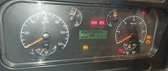
In order to diagnose a vehicle yourself, you need to install the KamAZ truck on an inspection pit or a special platform for carrying out repair work. After this, you need to start the power unit and let it warm up for 10-15 minutes. When starting the engine, the “Check” should light up in red for 2-3 seconds, and then go out along with the lamps reflecting the level of oil pressure in the system and the charge of the batteries. If everything went without failures or delays, it means that the system is working stably, without damage.
If the warning light does not go out, it is necessary to inspect the system for damage and defects.
To determine the malfunction, you need to press a special button, which is located on the left side under the steering mechanism, next to the fuse box. You must hold the diagnostic system button for 2-3 seconds, then release it and wait for the error code.
The received error code is correlated with the table given in the repair manual, and a series of works is assigned to eliminate the identified breakdown.
Error codes
Error codes KamAZ Euro-4 (engine):
| 11 | The gas pedal is out of order |
| 12 | Damage to the sensor that reflects the level of atmospheric pressure |
| 13 | Presence of damage on the housing of the atmospheric pressure measurement sensor |
| 14 | The clutch sensor has failed |
| 15 | Failure of the main crankshaft speed measurement sensor |
| 16 | Wrong polarity of sensors |
| 17 | Engine speed measuring device offset |
| 18 | Malfunction of the auxiliary mechanism that monitors the number of crankshaft revolutions |
| 19 | The main relay for turning on the electronic control unit has failed |
| 21 | Damage to the high pressure fuel pump |
| 23 | The gas pedal position does not correspond to the brake pedal position |
| 27 | The rack position sensor contacts are poorly connected to each other |
| 27 | Brake pedal malfunction |
| 29 | The electronic system control unit has failed |
| 31 | Problems with charge air temperature sensor |
| 32 | Cracks or other defects in the body of the charge air temperature measuring device |
| 33 | Malfunction in the turbocharging system |
| 36 | Coolant temperature sensor failure |
| 54 | Increased level of on-board voltage |
| 42 | Increased engine speed at idle |
| 41 | Invalid signal from multi-stage input |
Quality for any challenge
Unlike mechanical systems, repairing fuel injection pumps on Euro 3 Euro 4 cars is much more complex and expensive. Therefore, high-quality diagnostics and adjustments make it possible to prevent more complex breakdowns, replacement and repair of injectors and diesel equipment.
No matter what brand of car you use, we are always able to provide high-quality diagnostics and repairs to your truck.
Diagnostics and repair of trucks - we are No. 1 by right.
- Repair and maintenance of cabins and chassis
- Timely diagnostics - minus expensive repairs
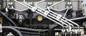
- Correct pulsation – diesel is healthy
- Hidden danger. Water in fuel
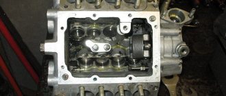
Adjustment of valves
In order to adjust the valves, it is necessary to install the dump truck on an inspection hole or platform, start and warm up the engine for 10-15 minutes, after which the engine must be allowed to cool. The vehicle must be on the handbrake or secured using special anti-roll devices.
To prevent accidental starting of the power unit while adjusting the valves, the high pressure pump lever should be moved to the stop position.
To adjust, you must perform the following steps:
- Remove the cover from the heads of the cylindrical elements.
- Check the tightening torque of the fasteners and the fastening of the heads.
- Place the flywheel locking device in the lower position.
- Remove the hatch cover, which is located at the bottom of the clutch housing.
- Rotate the crankshaft clockwise and install it so that the springs engage the flywheel.
- If a coincidence does not occur, disengage the latch and turn the crankshaft another 1 revolution.
- Use a special wrench to check the tightening torque of the rocker arm mounting nuts.
- Adjust the gap between the valves.
- Rotate the crankshaft 60°.
- Start the engine and check the operation of the entire system.
- Install all parts in place.
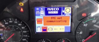
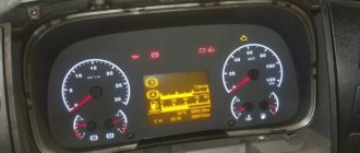
What to do if the icon appears
The first thing a driver needs to do when the “exclamation mark” icon appears is to postpone his trip (or stop if the icon appears while driving).
Then you need to try to understand why the icon appeared. To do this you need:
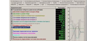
- Go to the “car status information” section of the on-board computer (if there is one) and find there the reason for the appearance of the icon;
- Check the brake fluid level in the reservoir under the hood and add fluid if necessary;
- Check the connector of the brake fluid level sensor (remove and clean), it happens that dirt gets under the connector casing or brake fluid fills it;
- Check the position of the handbrake and its limit switch, tighten and release the handbrake several times;
- Check the condition of the brake pads (if the wheels allow this); excessive wear on the pads may be the cause of a low brake fluid level;
- Check the operation of the brakes by pressing the pedal (if it is very soft or very tight, it is better not to drive the car again until the problem is eliminated);
- If you can’t independently determine the reason for the appearance of the “exclamation mark” icon, it is better to call a tow truck and take the car to a car service center, or try to find a good on-call diagnostician;
- If the nearest car service center is far away and there are no diagnostic specialists, you can try to read the errors yourself through the car’s diagnostic connector, via a special Bluetooth or Wi-fi adapter. For example, the ELM-327 adapter is very convenient and popular, which can be ordered with home delivery;
Features of valve adjustment KAMAZ 6520 euro 4 with engine 740.30-400
Below are the features of valve adjustment for KamAZ 6520 Euro-4 with engine 740.30-400:
- You need to unscrew all protective elements from the device.
- The flywheel must be down. Only in this position can further work be continued.
- Open the hatch, which is located at the bottom of the clutch mechanism.
- Using the torque mechanism, which must be connected to the flywheel, rotate it 1.5 turns forward.
- In this case, the process must be carried out slowly. The valves must be adjusted step by step.
On this type of engine, valve adjustment should be carried out on average once per 200 thousand kilometers. This is necessary because over time the gaps in this KamAZ spare part increase. If a metallic ringing occurs when starting the car, then you need to urgently check the valves of the heavy truck. Also, malfunctions in the valves of the 740.30-400 engine lead to a decrease in its power and an increase in fuel consumption.
Transmission
Transmissions produced by KamAZ production are traditionally distinguished by consistently high quality, durability and wear resistance. More modern boxes and advanced gearboxes from Zahnrad Fabrik are “conditionally imported”: their production was mastered in Naberezhnye Chelny. The Z-F variants are gradually naturally replacing the outdated domestic transmission on KamAZ trucks - “a legacy of Soviet times.”
With the engines of KamAZ-65115 dump trucks, as a rule, a mechanical 9-speed gearbox of the ZF-9 S1310 model is used with a range of gear ratios from 9.48 to 0.75. The transmission of rotation from the engine to the manual transmission is carried out using a single-disc diaphragm-type clutch with a hydraulic drive having a pneumatic booster. The final drive ratio is 5.94.
How to bleed the clutch
In order to bleed the clutch on a KamAZ, you need to prepare the following tools:
- wrench;
- pliers;
- screwdrivers;
- container for draining working fluid;
- rubber hose.
To bleed the coupling device, you need to install the vehicle in an inspection hole and secure it with anti-roll mechanisms. After this, you should raise the vehicle using a jack and remove the protective casing from the power unit.
Then it is necessary to remove the front wheel mechanism and caps from the fitting of the central cylindrical device. It is recommended to clean the surface of the fittings from accumulated dust and traces of working fluid.
After this, you can put a rubber hose on the front brake fitting and bleed the system so that no air flow gets there. To do this, you need to fill the hose with fuel liquid, put the end of the hose on the master cylinder fitting and open the safety flaps.
Then you need to press the brake pedal all the way, tighten the fitting on the front brake mechanism and lower the pedal. The procedure with the fitting should be repeated several times until air bubbles stop appearing in the storage tank.
How to make a car softer
There are several ways to make your car softer:
- Reducing tire pressure levels. This method has a drawback - fuel consumption increases and the performance of the braking system deteriorates. The braking distance will also increase and the controllability of KamAZ will deteriorate.
- Replacing the spring devices that are located on the shock absorbers with softer ones or shortening the existing springs. This will lead to a soft ride of the vehicle, but will lower the landing, which will affect the lifting properties of the dump truck.
- Replacing shock absorbers. This method should be combined with the replacement of spring devices and tires. This will make the ride smoother and increase the level of comfort while driving. It is recommended to install shock absorbers of oil or gas-oil type.
- Installation of pneumatic type suspension. This method will make the car softer due to the compressor and compressed air, which will smooth out all the unevenness of the road surface. The disadvantage of this method is the high cost of the equipment itself and its installation.
Owner reviews
Vitaly, 44 years old, Irkutsk: “I carried out repairs on the KamAZ-6520 myself. Replaced the rear suspension mechanism and carried out diagnostics of electrical equipment. “No difficulties arose during the repair work; all components were easy to get to.”
Alexander, 55 years old, Izhevsk: “I’ve been working at KamAZ for about 15 years. During this time, this car had to be repaired several times. The main malfunctions were related to the operation of the power unit and suspension mechanism. To diagnose the system, I recommend using special computer programs.”
Diagnosed KamAZ systems
Using special equipment, it is possible to service KAMAZ trucks with any configuration. Diagnostics of newer KAMAZ engines has its own characteristics and requires the use of auto scanners and analyzers such as Ascan, DK-5, Avtoas-Cargo, EDS-24. These devices allow you to diagnose the following electronic control systems:
- Cummins 6Isbe, 4Isbe
- Mercedes OM457La
- 740 BOSCH MS6.1
- 740 EDC7 Common Rail
- Gas M20.2-820
Diagnostics KAMAZ engine Cummins
Work aimed at identifying problems and malfunctions of a KAMAZ with a Cummins ISB 6.7e4 engine includes collecting the necessary indicators for diagnostics, thoroughly scanning the ECS, resetting and checking systems for errors in the electronic unit, checking all sensors responsible for the smooth operation of the engine for malfunctions. Also, the KAMAZ computer service package includes measuring the pressure level in the fuel system, testing the performance of the generator and analyzing exhaust gases using a four-component gas analyzer. Quite often, for KAMAZ vehicles with a CumminsISB 6.7e4 engine, the procedure for flashing the power unit becomes necessary. This process allows you to significantly improve the transmission dynamics in the transmission, adjusts the operation of ABS, brake pads and directional stability. Reflashing can also provide more sensitive steering response with variable power steering and adjust the smoothness of the vehicle. Computer diagnostics of KAMAZ are carried out exclusively by certified professional workers using modern computer technologies, analyzers, etc.
Instructions for repairing trucks
Home » 2013 » October » 21 » KAMAZ fault codes EURO 3
12:31 KAMAZ fault codes EURO 3
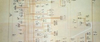
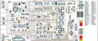
KAMAZ fault codes EURO 3 Diagnostics are carried out based on the lighting of the diagnostic light. We press the key on the panel as in the photo below - and wait how many times the light bulb will blink after that. For example, one long light, three short codes 13. If you press again, the next error code (if any) will blink. As noted, the most common three error codes are: “99”, “34 and 55”. The reason for the first two It’s clear: somewhere there’s a bad connector or connection. (I wish I knew where!) And code 55 means that the vehicle was turned off less than 5 seconds after turning off the ignition. Of course, this is even described in the car’s operating manual, but do drivers always read them? In most cases, it will be possible to “reset the error” using the same button (but with the engine turned off). If the problem does not go away, then the repairmen simply remove the main chip from the brains under the front panel for a few seconds and insert it back. Sometimes it even helps. The table below in the right column indicates how the engine will behave in the event of a particular error. That is, the engine control computer switches to one or another emergency program. In most cases, the car will move with restrictions in order to get to the nearest service stations ECM pump BOSCH type 7100: Crankshaft speed sensor Coolant temperature sensor Charge air pressure and temperature sensor pump rack electromagnet ; Retractor electromagnet; Fuel pedal – TeleflexMorze; Diagnostic warning lamp. Diagnostics . Possible malfunctions , their blink codes , limitations, solutions: fault code - 11 Accelerator pedal malfunction. nmax=1900 min-1. Check the connection of the accelerator pedal. Malfunction code is 12. Malfunction of the atmospheric pressure sensor. Nmax=300 hp You can continue driving. The fault code is 13. Physical error in the atmospheric pressure sensor. Nmax=300 hp You can continue driving. The fault code is 14. Clutch sensor malfunction. nmax=1900 min-1. Check the clutch sensor. You can continue moving. Do not use the cruise control function. DTC is 15. Malfunction of the main speed sensor (crankshaft). nmax=1600 min-1. Check the condition and connection of the corresponding engine speed sensors; fault code – 16,17. Wrong polarity or reversal of speed sensors. nmax=1800 min-1. You can continue moving. Inspection is required at a service center; fault code is 18. Malfunction of the auxiliary speed sensor (camshaft). nmax=1800 min-1. You can continue moving. Inspection by a service center is required. Malfunction code is 19. Malfunction of the main relay. There are no restrictions on use. Check the main relay and its connection. You can continue moving. Inspection is required at the service center; fault code is 21,22,24-26. Fuel injection pump malfunction. The engine may not start. Check the contact of the injection pump connector. An urgent inspection is required at the service center. Malfunction code is 23. Inconsistency between the position of the accelerator pedal and the brake pedal. Nmax=200 hp Check the accelerator pedal, it may be stuck. An urgent inspection is required at the service center; fault code is 27. Poor contact of the rack position sensor. Check the contact of the injection pump plug. Contact a service center immediately; fault code is 28. Malfunction of the brake pedal sensor. Nmax=200 hp Check the brake pedal sensor and brake relay. You can continue moving. Inspection is required at a service center; fault code is 29.51-53.81-86, 99. ECU malfunction (hardware). The engine may not start. Contact a service center immediately; fault code is 31. Charge air temperature sensor is faulty. Nmax=300 hp Check charge air temperature sensor. You can continue driving. The fault code is 32. Physical error in the charge air temperature sensor. Nmax=300 hp Check charge air temperature sensor. You can continue moving. Inspection is required at a service center; fault code is 33. Charge air pressure sensor is faulty. Nmax=250 hp Check the charge air pressure sensor. You can continue moving. Inspection is required at a service center; fault code is 34. Physical error in the charge air pressure sensor. Nmax=250 hp Check the charge air pressure sensor. You can continue moving. Inspection is required at a service center; fault code is 35. Malfunction of the cruise control control module. There are no restrictions on use. Check the connection of the cruise control lever. You can continue moving. Contact the service center. This error also appears due to the simultaneous pressing of several control elements of the cruise control lever; fault code - 36. Coolant sensor malfunction. Nmax=300 hp, nmax=1900 min-1. Check the coolant temperature sensor. You can continue moving. An inspection is required at the service center. The fault code is 37. Physical error in the coolant sensor. Nmax=300 hp, nmax=1900 min-1. Check the coolant temperature sensor. You can continue moving. Contact a service center; fault code – 38 Fuel temperature sensor malfunction. . nmax=1900 min-1. Check the fuel temperature sensor. You can continue moving. Inspection is required at a service center; fault code is 39. Physical error in the fuel temperature sensor. nmax=1900 min-1. Check the fuel temperature sensor. You can continue moving. Inspection is required at the service center; fault code is 41. Incorrect signal from the multi-stage input. There are no restrictions. You can continue moving. Inspection is required at a service center; fault code is 42. Exceeding the maximum permissible engine speed. After a complete stop of the engine, a new start is possible. If the excess is due to incorrect gear shifting from high to low: check the engine. If the engine is OK, you can start the engine and continue driving. If the engine spontaneously increases speed, do not start the engine! Inspection at the service center is urgently required; fault code is 43. Vehicle speed signal error. nmax=1550 min-1. Check the connection of the tachograph to the ECU. You can continue moving. Inspection is required at a service center; fault code is 54. Excess of on-board voltage. There are no restrictions. Check battery charging; fault code - 55. Incorrectly completed ECU operating cycle. There are no restrictions. This error appears due to the mass being turned off earlier than 5 seconds. after turning off the ignition or interrupting the power supply to the computer. You can continue driving. The fault code is 61-76. CAN line fault. There are no restrictions. Check the connection of the CAN line to other CAN devices (ABS, automatic transmission...). You can continue moving. Contact the service center. Kamaz 5410 color electrical diagram Official Kamaz fuel consumption standards If a Kamaz with a CUMMINS engine does not start - diagnostics of cars with a CUMMINS engine Kamaz, diagnostic error codes for “CUMMINS” engines Injection pump models and injectors of KAMAZ engines and their interchangeability
5516 | Added by: auto electrician | Rating: 0.0/0
Total comments:
Diagnostics of KAMAZ with COMMON RAIL engine
The main malfunctions of KAMAZ engine electronic control systems are the following:
- Malfunction of the fuel system, damage to the pump
- Damage to the winding of the electromagnetic fuel supply regulator
- Damage, wear of the engine block
- Short circuit in inductive sensor coils
- Pulse gear beating
The common rail fuel accumulator system is used exclusively in diesel power units and serves to supply fuel to the engine. In this system, the pump supplies fuel under a pressure of 300 MPa. The injectors, controlled by an electronic system, inject fuel into the cylinders also at high pressure. Another distinctive feature of the Common rail fuel system is the complete independence of injection from shaft rotation angles and from the operation of the power unit. Due to this feature of the Common rail system, the use of special equipment is necessary to diagnose KAMAZ vehicles. To service KAMAZ vehicles with an electronic common rail system, the EDC7UC31 BOSCH control unit and the MS 6.1 engine ESU, a special EC-200 stand is used. This device makes it possible to almost accurately test injectors according to the manufacturer’s test plan. In addition, the EC-200 allows for automated diagnostics, measuring the parameters of Common Rail injectors and pumps, checking injectors under pressure up to 2000 bar, and measuring the consumption of fuel fluids at critical loads and idling.
What does the error code consist of?
The error that is visible during diagnosis consists of letters and numbers. The letter at the beginning of the code indicates the location of the error - the system in which the problem was noticed. The letter P indicates problems with the functioning of the internal combustion engine or gearbox, B indicates a problem in one of the body systems (power windows, locks, airbags), C indicates problems with the chassis, and U indicates that the failure lies in the system of interaction between the modules electronic system. The second character is usually a number, which indicates the specifics of the problem, and the third indicates the type of breakdown. If there are more numbers in the fault code, you can use them to determine the fault number.
Diagnostics of KAMAZ with a gas engine
In the process of servicing and diagnosing KAMAZ vehicles with installed gas power units, it is necessary to comply with a number of rules and safety precautions. This is due to the increased risk of working with compressed natural gas. Basic rules and features of computer diagnostics of KAMAZ with a gas engine:
- You cannot replace gas engine parts with parts from diesel power units.
- It is impossible to use motor oil that does not correspond to that specified in the vehicle's technical data sheet.
- Spark plugs must have a gap of more than 0.4 millimeters. Adjustment of the gap should be carried out every 10-12 thousand kilometers, replacement - 30-35 thousand km.
- Welding work is carried out with disconnected connectors of electronic units and control systems, including ABS and batteries.
- Computer diagnostics of the electronic power unit control system is carried out using an ASKAN-10 scanner or the AKM Lite computer program.
Application of diagnostic scanners
Today, the automotive industry provides a wide range of computer diagnostic equipment, with the help of which it is possible to identify malfunctions of KAMAZ vehicles of various types.
The DK-5 autoscanner is an updated version of the DK-2 scanner. It is necessary for carrying out diagnostic work on the electronic unit, reading and setting control system parameters using computers with USB ports. This scanner can be used under certain conditions, or more precisely at air humidity of no more than 80%, temperature up to +30°C and pressure from 85 to 105 kPa. Under correct operating conditions, the DK-5 autoscanner provides communication between the computer and electronic control systems via the K-Line, reads operating errors, changes system parameters and automatically calibrates the pedal, adjusts the idle speed, positions the injection pump rails in the desired position, etc. P.
The EDS-24 scanner is a software and hardware complex for computer diagnostics of trucks with MM3-245 engines and BOSH MS6.1 control units. This complex consists of a USB-KLine adapter with galvanic isolation, which allows operation at low voltage. The design also includes a disk with the necessary software for KAMAZ vehicles with a common rail injection system, etc.
The ASKAN autoscanner provides the ability to carry out computer diagnostics of various control systems, reflash the control unit with new versions from manufacturers, read the necessary parameters and data from the unit, display graphs on the LCD display in real time, write the received information into memory, read fault codes and store them in memory . This scanner is one of the most functional devices, which allows you to obtain the most accurate data in a record amount of time. The main technical characteristics of the scanner include a fairly large amount of internal memory - 8 MB, the ability to support physical layer exchange protocols ISO 14230, SAE J1850 and ISO 9141, data transfer speed via the USB 1.1 port.
Toyota self-diagnosis
Modern Toyota cars, and other brands as well, are quite progressive mechanisms that have the ability to automatically control their own systems and sensors.
If errors are found in operation, they signal the driver about the presence of a malfunction on the dashboard with a warning indicator lamp.
Models with a digital display may even display an error code or the name of the faulty unit.
Toyota self-diagnosis begins with the fact that you first need to locate the corresponding diagnostic connector. This connector may be located under the hood, in the engine compartment and/or under the driver's instrument panel. In cars of this brand, three different types of self-diagnosis connectors were used:
Connector type DLC1 is located in the engine compartment, and connectors DLC2, DLC3 are located under the driver’s dashboard.
Errors during self-diagnosis are read by the blinking of the indicator lamp of the corresponding readable unit. For example, engine malfunctions must be read by the flashing of the “Check engine” lamp (engine image).
How to do a Toyota self-diagnosis?
In order to start engine self-diagnosis, you need to close the “TE1” and “E1” contacts in the DLC1, DLC2 connectors in the diagnostic connector with a paper clip, and if self-diagnosis is carried out using the DLC3 connector, then close the “TC” and “CG” contacts. The location of the contacts, by the way, is usually located under the protective cover of the connector.
After this, turn on the ignition and observe the warning lamp. If there are no faults, the lamp blinks constantly at a frequency of a quarter of a second.
If there are problems, the blinking of the lamp displays the fault code in digital form. First of all, the number of tens is displayed by long moments of lamp burning, after (after 1.5 seconds) units are displayed by more frequent blinking of the lamp.
For example, three long and two short lamp beeps indicate code “32”. If there is more than one fault in the memory, then the next code is displayed after an interval of about 2.5 seconds.
All codes are repeated in a cyclic circle, the pause between rows of codes in a circle is 4.5 seconds.
You can decipher the code using the table of fault codes for your car. This table is very often published in service books for repairing a specific car.
In addition, the World Wide Web contains special sites with databases of fault codes for most modern cars and their decoding; application stores of modern smartphones, by the way, can also contain programs of this kind, which is very convenient.
In the same way, you can diagnose other systems:
To do this, you need to close or open the necessary connectors in the diagnostic block. Which connectors need to be closed to diagnose the corresponding mode in brief:
- The automatic transmission is read by the “O/D OFF” lamp (connector DLC1: “TE” – “E1”; connector DLC3: “TC” – “E1”);
- SRS by the corresponding “SRS” warning lamp, sometimes it is found in the form of a pictogram of a deployed airbag (connector DLC1: “TE” – “E1”; connector DLC3: “TC” – “E1”);
- 4WS system also by the corresponding indicator (DLC1 connector: “TC” - “E1”);
- ABS system (the connectors in DLC1 are closed: “TC” – “E1”, and the jumper from “WA” – “WB” is removed; after reading is completed, the jumper must be returned to its place).
In conclusion, I would like to note that the Toyota self-diagnosis system is the first direction of movement towards a malfunction. And we cannot immediately talk about a specific failure of any sensor, because a simple interruption in the power supply to the circuit or its contamination is possible. So, having decided on the direction, it is necessary to test a specific node for performance.
Video