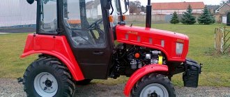
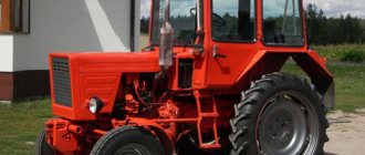
Tractor T-40: technical characteristics and intended purpose
T-40 is a wheeled tractor designed for use in the agricultural and road sectors.
Traction class 0.9. Manufacturer: Lipetsk Tractor Plant. Release period: 1961-1995. The tractors are now out of production, but are still in use. The reasons for the long service life are the durability of the design, versatility and optimal conditions for repair: all spare parts are available.
Monitoring and control devices
A description of the T-40AM device will be incomplete without talking about the driver’s working conditions. The tractor was equipped with a metal closed cabin with two doors. The cabin had a rigid safety cage inside. The roof was made of plywood covered with leatherette.
Optionally, a cabin with improved characteristics could be installed. It was equipped with a heating system with an additional fan. The coolant for the heating system was heated oil from the tractor hydraulic system.
At the rear of the cabin there was a tool box and a fuel tank with a capacity of 70 liters. The tank is equipped with a measuring ruler to control the fuel supply.
The driver's seat is adjustable for firmness and distance from the steering wheel. The back has three fixed positions according to the angle of inclination. The steering column could be adjusted in angle. The instrument panel is equipped with all the necessary indicators and switches.
A roll sensor is installed on the windshield, clearly visible to the driver. When dangerous angles are reached, the sensor signals this with light and sound indication.
General characteristics of the T-40
Purpose:
- plowing;
- processing of field crops;
- mowing;
- hay harvesting, baling;
- snow clearing;
- bulldozer and transport work.
Operational features:
- high cross-country ability;
- good maneuverability (thanks to the reverse transmission, all the functionality of the machine is available in reverse);
- adjustable track and clearance;
- two power take-off shafts;
- Various options for installing wheels depending on the specific purpose.
Launchers
The engine could be equipped with an electric starter or a PD 8 gasoline starting engine. Most often, the Vladimir plant produced engines equipped with an electric starter. Depending on the type of starter, the tractor was equipped with batteries of different capacities.
“Puskach” PD 8 was a small two-stroke air-cooled engine with a power of about 7 hp. The fuel used was a mixture of low-octane gasoline A 76 and oil. The fuel supply was in a separate tank with a capacity of about three liters, located under the hood of the main engine.
The PD 8 engine had its own magneto ignition system. To start the engine, a separate electric starter was provided, which was usually not used, resorting to the manual method using a cord.
A decompression mechanism and an electric spark plug were used as starting auxiliary devices to heat the air supplied to the cylinders. The spark plug was installed at the beginning of the intake manifold. The decompressor could be used as an emergency means of stopping the engine.
Optionally, the tractor could be equipped with a 5PP 40A starting device. This device sprayed easily evaporating ether into the inlet pipe, which significantly facilitated starting in low temperature conditions.
Advantages and disadvantages of the T-40 tractor
Pros:
- High cross-country ability on any soil.
- Ease of maneuvering at any speed.
- All tractor functionality is available in reverse.
- Ease of control.
- Versatility: the ability to be equipped with attachments for other types of machines (T-25, “Belarus”).
- No problems with spare parts and maintenance.
- Reliability, durability.
- The steering of the tractor is equipped with power steering.
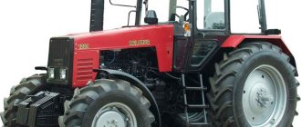
T-40 tractor with attachments
Cons
The main disadvantage of the tractor is the air cooling of the engine. Because of this, operational difficulties arise:
- Cooling is not effective enough in hot weather.
- It is difficult to warm up the engine before starting it in winter.
- Lack of heating and air conditioning in the driver's cabin, which makes work in hot and cold conditions uncomfortable.
Engine
Tractors based on the T-40 were equipped with a four-cylinder 37-horsepower diesel engine model D37. The air-cooled diesel engine was produced at the tractor plant in Vladimir. The T-40AM tractor (like all modernized machines) was equipped with a more powerful 50-horsepower D144 diesel engine. In some early instructions, the engine model is indicated as D 37E. The plant guaranteed the declared engine power only after running-in and an additional 60-hour operating time.
Structurally, the D37 and D144 engines are identical and consist of a crankcase with an oil pan on which individual cylinders are installed. The cast iron cylinder body has extensive fins to ensure reliable cooling. A characteristic feature of the diesel engine of the T-40AM tractor is the combustion chambers made in the body of aluminum pistons.
The rigid crankcase houses a five-bearing crankshaft and camshaft. The camshaft drive is gear-type. The cylinder heads are individual, with developed fins for better cooling, and have two valves each. The valves are driven from the camshaft by rods and rocker arms.
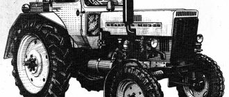
Modifications
With D-37 engine
The base model has rear-wheel drive. Its modifications are made with all-wheel drive:
- T-40A – presence of a front axle. Front-wheel drive engages automatically in accordance with driving conditions;
- T-40AN - the tractor is adapted for working on a steep slope, the height and ground clearance are less than the basic version;
- T-50A is an industrial modification, adapted for a single-bucket loader.
With D-144 engine
The T-40M has rear-wheel drive, while the modifications have all-wheel drive:
- T-40AM - unlike the T-40M - front axle with drive;
- T-40ANM - a powerful analogue of the T-40AN: reduced ground clearance for working on a steep slope (up to 20 degrees), lower height, greater stability;
- T-40AP is an industrial model, adapted for working with road equipment.
Motor specifications
Initially, T-40 tractors were equipped with a D-37 engine, the power of which was 37 hp. With. Today, VMTZ OJSC produces this engine, and it is labeled as D-144. There are two options, with a power of 37 and 50 hp. With. The technical characteristics of these models are most conveniently presented in the form of a table:
D-144 engine diagram
| Specifications | D-37 | D-144 |
| Dimensions, mm | 919*741*848 | 919*741*848 |
| Weight, kg | From 375 to 390 | From 375 to 390 |
| Shaft rotation speed, rpm | 1500 | 1800 |
| Number of cylinders, pcs. | 4 | 4 |
| Cylinder volume, l | 4,15 | 4,15 |
The four-stroke engine runs on diesel fuel (diesel fuel). Cooling type: air. New models have an electric starter; older models were started using a PD-8 starting motor that ran on gasoline.
Adjustment of valves
The gas distribution mechanism of the T-40 tractor engine from time to time needs to be checked and the most precise adjustment of the valves, which is usually performed not as a repair, but as an operating procedure by the machine operator himself.
According to technical rules, such an adjustment must take place every 480 hours of tractor operation (that is, at least every 20 days). The T-40 engine has a standard 4 valves - two exhaust and two intake to introduce fresh air into the cylinders, release exhaust gases and protect the combustion chamber. For D-36, D-37 engines they have plates of different diameters - the exhaust plates are 4 mm smaller. The valves are actuated by the lateral force of the rocker arms on their stems. It is in adjusting the size of the gap between the rocker arms and the valve stems, as well as in ensuring the tightest fit of the valves to the seats, that the adjustment of this mechanism lies:
- If the clearance between the valves and the rocker arm is too small, then unwanted gas leakage may occur,
- If this distance is large, this can cause knocking and rapid wear of parts.
- The drive pulley sets the position of the piston of the first engine cylinder to the final compression position until the intake and exhaust valves close.
- The rear universal joint wedge is removed. This can be done by moving the shaft while turning the steering wheel towards you, then the cardan can be easily moved to the side.
- The locknut at the rocker arm adjusting screw is loosened.
- The gap size is checked with a special probe. Ideally, with a cold engine it should be exactly 0.3 mm.
- The size of the gap is adjusted by changing the degree of tightening of the screw (tightening it more or loosening it).
- The value is checked again using a probe.
- If the control data is satisfactory, the locknut is installed back and tightened.
The video shows the T-40AM tractor in action:
How to adjust valves on the T-40 tractor
The distribution device includes:
- camshaft;
- gas distribution gears;
- valve mechanism equipped with an actuator.
The drive includes rocker arms and the rocker arms themselves, as well as other elements of the mechanism. Among them:
The gas distribution device performs its functionality in a certain way. So, the process begins with the activation of the camshaft: this is done due to the interaction of the crankshaft gears with the camshaft and the gear located between them. When the camshaft operates, the pushers rise and through other elements of the installation the process of opening the valves is carried out: exhaust and intake. After this, the movement continues, the cam moves away from the pusher and, under the constant influence of a special spring, the valve gradually closes. The active elements then return to their starting location. Upon completion of all these actions, the cycle is repeated from the very beginning, as required by the gas distribution phases.
In order for the device in question to work simultaneously with the fuel supply system, the camshaft gears, namely the fuel pump and the intermediate wheel mount, must be mounted exactly where it is provided by special marks indicated on the gears.
Let's look at how valves are adjusted on the T-40 tractor. The gas distribution mechanism requires regular, careful specialized maintenance, which involves aligning and aligning the spaces of the tractor valves T. In addition, it is necessary to ensure that all components of the camshaft are sufficiently lubricated, as well as how tightly they fit to the places where they are supposed to be .
Experts recommend carrying out maintenance after at least 480 hours of operation.
Check the installation order of these parts and, if necessary, adjust the distances between the valve stems and rocker arms. If the engine has not been preheated, the distance between the exhaust and intake must be at least 0.3 mm.
Answering the question of how to adjust tractor valves, let’s consider the standard adjustment of T-40 valves. Before starting the procedure, you need to understand that you will have to maintain a certain sequence.
The valves on the T-40 are adjusted only when the tractor engine is cool. Before carrying out work, it is necessary to slightly unscrew the lock nut of the adjustment screw, which is located on the rocker arm, and, constantly tightening the screw, set the gap that will meet the requirements. In this case, it is recommended to use a special probe. After equalizing the gaps, you need to tighten the locknut and finally measure the gap.
The process of adjusting the valves on the T tractor completely repeats the process of functioning of the power plant in order. So, using special marks on the fan drive pulley, it is necessary to install the starting cylinder. The element must be mounted in the position corresponding to the end of the compression step. Both tractor valves must be closed. Next, when repairing parts of other cylinders, it is necessary to gradually turn the crankshaft using a key half a turn clockwise.
When is it necessary to adjust valves on a tractor?
If the tractor engine is not operated continuously, the valves may last for a long time without requiring repairs. To prevent the valve from breaking when it is torn off along the groove, it is necessary to leave pairs of “crackers” intact if the valve device is dismantled. If gears need to be replaced, they must be inserted into the clutch only as indicated by the manufacturer's markings.
A mechanism such as a decompressor is needed, first of all, to make starting a cold engine easier. In addition, a decompressor is needed when sudden braking of a power plant running on diesel fuel is required. This mechanism is a combination of two control pairs: manual and racks, which are connected to the rack using hinges. The levers are fixed to the forks in a rigid manner.
It is worth noting that the adjustment process is not complicated, but if the tractor is used correctly, it does not need to be done often. This is especially true for D-144 valves (diesel engines) - they are easy to operate and do not require complex manipulations during repair.
Cooling system
The technical characteristics of the T-40AM corresponded to the declared ones only if the engine was properly cooled, which was carried out by an air flow from an axial fan. In the fan air intake channel there was a rotary disk, with the help of which the intensity of the air flow was regulated. The entrance to the channel was equipped with a protective mesh that prevented foreign objects from entering the fan.
The forced air entered the guide casing mounted on the cylinders and exited through the fins on the cylinders and heads. There are additional deflectors inside the casing for better distribution of air flow between the cylinders. The fan was driven by two belts from the engine crankshaft.
An oil radiator served as an additional means of maintaining engine temperature, which could be turned off during the cold season. The oil radiator is located inside the guide casing and is blown by the air flow from the fan.
When operating the tractor in winter, it was recommended to cover the engine hood with an insulating cover. This insulation was supplied by the factory upon request. The cooling system was monitored by an oil temperature sensor and a warning light that came on when the fan drive belt broke.
How to adjust valves on T-40
The gas distribution mechanism (GDM) ensures the execution of a four-stroke cycle in the engine cylinders. The operation of the engine and, consequently, the remaining mechanisms of the tractor depends on its serviceability. It is “responsible” for air intake and exhaust gases. If the engine “sneezes”, has difficulty starting, or is unstable, this may be due to a problem with the timing belt. To avoid breakdowns, regular inspection of the mechanism and adjustment of the T-40 valves after every 480 hours of engine operation are recommended. This work can be done by a professional mechanic, but can also be done by a tractor owner with minimal engine skills.
Valve settings
During operation, the valves increase in length by tenths of a millimeter. This seemingly insignificant expansion requires compensation, for which a gap is required between the end of the valve stem and the rocker arm. Adjustment of the valves of the T 40 tractor is ensured by a special adjusting screw. When screwing it in, the valve lever arm rises and the gap decreases; when unscrewing, the opposite is true. It must be taken into account that the gap at the inlet should be smaller than at the outlet, since the latter heats up more.
The gap size is checked with a special probe. It should be 0.3 mm. The check is carried out only on a cold engine. In addition to adjusting the gaps, timing maintenance includes checking the tight fit of the valves to the seats and the presence of lubricant, as well as the wear of seals, bushings, etc.
Tractor operation today
Despite the fact that the “magpie” has not been produced for more than 20 years, it continues to serve its owners well. Finding a used T-40AM on the secondary market is not difficult. Most often, a machine is purchased for cultivating small plots of land.
The fuel efficiency of the tractor, its versatility and low price become decisive factors when purchasing. It is important that many spare parts are suitable for common MTZ tractors. Maintenance can be carried out without special tools and does not require highly qualified personnel.
Owners should remember that the tractor is very picky about the cleanliness of the engine fins. If they are clogged with dirt and oil, the engine will overheat very quickly and there is a risk of fire.
How to adjust valves on T-40
Procedure:
- For ease of operation, move the cardan shaft to the side. To do this, you need to remove the holding device and pull the shaft together with the steering wheel towards you.
- Set the piston of the first cylinder to the end of the compression stroke position. This is done by aligning the TDC (top dead center) marks and the pointer on the fan pulley. Close both valves.
- Loosen the lock nut of the adjusting screw and, by unscrewing or tightening the screw, set the required clearance. Be sure to use a dipstick.
- Tighten the locknut and measure the gap again by turning the pusher rod.
- Rotate the crankshaft half a turn clockwise to adjust the valves of the following cylinders.
- The procedure for adjusting the T 40 valves is 1-3-4-2.
All work is performed only on a cold engine. When the engine is warm, the size of the valves changes, and unevenly - the exhaust valve lengthens more than the intake valve. This will inevitably cause measurement discrepancies.
Before starting work, it is recommended to watch the adjustment video and prepare the tools in advance: wrenches for turning the crankshaft and a 0.3 mm feeler gauge.
Tractor decompressor
The decompressor is a compact but important mechanism that ensures reliable starting of the engine in cold weather after an overnight stay, as well as its quick stop. Problems with its operation may also be due to improper valve adjustment.
The mechanism includes a set of levers connected to a rack and rollers, the ends of which fit into the grooves of the intake valve pushers. Thus, the movement of one mechanism entails the movement of another and this is important to take into account when diagnosing.
If there are problems with the decompressor, check the degree of wear of the bushings and the integrity of the rocker arms. Only after this does it make sense to look for the problem in the mechanism itself.