There are hardware and visual ways to check a car's generator. However, the owner must know the design and purpose of this electrical device in order to diagnose correctly. This guide will help you avoid a trip to the service station and save your operating budget.
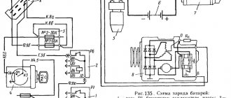
Rice. 1 Checking the car generator
Before you test the generator with a multimeter on your own, you need at least minimal knowledge about the design of the electrical appliance:
- the belt transmits rotation from the engine crankshaft to the generator pulley
- mechanical energy is converted into electrical energy
- diode bridge changes alternating current to direct current
- The regulator relay is responsible for recharging the battery when it is discharged during engine startup
- the rest of the voltage is spent on electrical appliances of the machine
Rice. 2 Design of a car generator
Both undercharging and overcharging are harmful to the battery, so the voltage at the terminals must have stable characteristics at any speed. At the same time, the connecting unit, dimensions, layout and quality of manufacture of generators may differ significantly from different manufacturers and for specific car modifications.
Circuits and terminals
Before you check the generator on your car on your own, you need to know the electrical diagram of this unit and the purpose of the terminals on its body. The most popular are 6 schemes; for example, one of them is shown in the bottom photo.
Rice. 3 Example of electrical circuit
For ease of reference, the digital designations on all diagrams are the same:
- generator block
- exciting winding
- stator winding
- rectifier
- switch
- warning lamp relay
- voltage regulator
- indicator lamp
- noise suppression capacitor
- transformer/rectifier unit
- battery
- zener diode
- resistor
The terminals on the case are not designated the same, which may interfere with correct diagnostics with a multimeter (tester):
- positive terminal of the power rectifier - VAT; B+; thirty; B or "+"
- exciting winding – FLD; E; EXC; F; DF; 67 or Ш
- output for the control lamp from the backup rectifier – IND; W.L.; L; 61; D+ or D
- phase – STA; R; ͠ or W
- zero – MR or “0”
- output for “+” battery – B; 15 or S
- terminal for connection to the on-board computer – F or FR
- output to ignition switch – IG
Rice. 4 Location of pins on the housing
In the Russian Federation, generators are most often used, the exciting winding of the voltage regulator of which is connected to the on-board network by the negative side. Although there are options with a “+” attached to it.
In cars with diesel internal combustion engines, two-level 14/28 V power plants can be installed. Checking these generators is more difficult; it is better to carry it out at a service station.
Self-test of the generator
The simplest option for checking a generator at home without a trip to the service center is a visual inspection and searching for extraneous sounds. However, these methods cannot identify all existing defects. For example, the glow of a lamp on the dashboard indicates that the battery is not being recharged. In this case, the battery itself may be faulty or the generator is supplying insufficient voltage to its terminals.
Therefore, it is better to arm yourself with a tester or its more modern version of small dimensions - a multimeter for high-precision diagnostics. Most breakdowns can be identified locally; to find and repair the rest, you need to check the removed generator by partially disassembling it.
Safety precautions
In order for diagnostics to be safe for the user and the electrical part of the car, the following conditions must be met:
- using a tester, multimeter or instruments to measure current, voltage and resistance separately
- additionally disconnecting the battery from the on-board network and from the generator
- when replacing wiring, maintain the length and cross-section of the cable as the original parts
- make sure the belt tension is normal
It is prohibited to perform the following actions:
- use sources with voltages greater than 12 V
- turn off consumers when the engine is running and the generator belt drive is connected
- close terminal B+ (aka 30) to ground or terminal D+ (67)
- check the spark to the body with a short circuit
It is recommended to let the engine run for ¼ hour at medium speeds with the headlights on low beam before starting hardware diagnostics.
Visual inspection
First of all, the owner is interested in how to check the generator on a car without removing this electrical device. Therefore, faults can be diagnosed in the following ways:
- charging lamp - if it lights up on the panel, either the charging voltage is insufficient, or the battery has exhausted its life
- third-party sounds - noise, whistling and rustling indicate weak belt tension, a worn bushing or bearing
- burning smell - can penetrate through the stove into the interior, the likely cause is high-temperature heating of the windings
- electrical interruptions - indicate insufficient current produced by a running generator
Rice. 5 Battery charging lamp
The belt can be tensioned without removing the entire assembly; other faults can be eliminated only after dismantling the generator.
Rice. 6 Checking the tension of the generator belt
Bearings (bushings)
The generator shaft rotates in two rolling bearings. The first is fixed on the shaft itself and is removed along with the anchor. The second is pressed into the stator in its central part. In this case, diagnosis is made aurally and visually:
- Whistle and hum with normal belt tension are signs of a worn-out bearing or a loose race.
- when turning the shaft manually after removing the belt, it should rotate freely, there is no lateral play
Rice. 7 Replacing the generator bearing
Otherwise, distortions, jamming, burnout of the windings, and spillage of the armature magnets are possible. In any case, a reduced voltage will reach the battery, insufficient for recharging.
Windings
This unit is the only one in the generator whose visual diagnostics are more effective than using a tester for a number of reasons:
- With intense heating, the varnish coating of the copper conductor darkens
- there is a burning smell
- The winding resistance is too low to accurately diagnose a short circuit.
Rice. 8 The burnt-out winding has dark-colored wires
It should be noted that before checking the generator for operability, in this case you will have to disassemble it by removing it from its seat. If the electrical appliance is in good working order, the varnish coating will be light by default.
Commutator group and brushes
Before checking the generator for wear of these friction parts, you need to disassemble it:
- brushes are adjacent to cylindrical brass contacts - collectors
- Most often the brushes wear out, it is better to replace them as a set
- wear of the collector group is determined visually by the grooves that appear
- the collectors can be ground 3-4 times, then they will have to be replaced entirely
Rice. 9 Production of collector rings
At this stage, the car owner does not have any problems.
Attention: The “old-fashioned” method of checking the functionality of the generator - removing the minus terminal after starting the internal combustion engine and not stalling the engine, is unacceptable for modern cars. Moreover, on fuel-injected cars it is better not to let them “light” with wires from the battery connected to the on-board system. The “check” error may light up.
Rice. 10 “Lighting” from a car is prohibited
Hardware diagnostics with a multimeter
The best option for checking a car generator with your own hands is to use instruments: ohmmeter + voltmeter + ammeter or tester (multimeter). The last option for checking the serviceability of the generator is preferable, since you can also ring the diode bridge with a universal device.
Diode bridge
Structurally, the bridge consists of 6 diodes - 3 of them are considered negative, the remaining positive. In fact, they are turned in opposite directions in the circuit, passing current in only one direction.
There are two options for checking a car alternator for the integrity of the diode rectifying bridge:
- without removing the unit - diagnostics are carried out after disconnecting the battery ground, the wires from the voltage regulator and the diode bridge, the tester is switched to ohmmeter mode, its plus (red wire) is connected to the 30th terminal of the generator, the minus (black wire) is shorted to the body of the electrical device, all diodes are intact if infinity appears on the multimeter scale, broken - if some value in Ohm is displayed
- after dismantling and partial disassembly - positive diodes are checked in the same way, negative ones - on the contrary, in both cases the specific resistance value on the tester indicator becomes a sign of breakdown
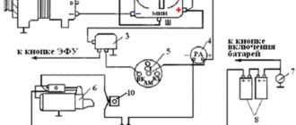
Rice. 11 Generator rectifier diagnostics
Attention: If you make a mistake with the polarity when connecting the battery, it is the diode bridge that fails.
Rotor and stator
If checking the mechanical part does not reveal any problems, the operation of the generator is checked further after disassembling it:
- stator - you need to check the generator winding for each turn, the resistance is about 0.2 Ohm, so you will need an accurate instrument, you can use the non-hardware methods discussed above
- rotor - if a modification with permanent magnets is used, you just need to reinstall them inside the cage, conventional rotors have only 2 windings, the resistance of each of which is 2 - 5 Ohms, if the tester shows infinity, then an insulation breakdown or wire breakage has occurred
Rice. 12 Checking the stator with a multimeter
Rice. 13 Diagnostics of the field winding
For a more detailed diagnosis of whether the generator is working, the starter needs to be checked additionally, but already included. To do this, the resistance between the terminal of any winding and their common “zero” is measured; it should be 0.3 Ohm.
Battery charging voltage regulator relay
To avoid mistakes, before checking the charging of the car’s generator, you should consider the following nuances:
- Normal for a car battery is considered to be a voltage of 12.5 - 12.7 V at its terminals, that is, in the entire on-board network with the engine off
- at idle speed with the engine turned on, it reaches a value of 13.5 - 14.5 V; for some foreign cars the normal voltage is 14.8 V
- at higher speeds, the generator voltage drops to 13.7 V
- if the device shows 13 V when the internal combustion engine is running under load, the generator definitely needs repair
- Overcharging 15 V is dangerous because the electrolyte boils and the plates of the acid battery begin to crumble
- undercharging of 13 V will not allow the battery to accumulate the electricity expended when turning the flywheel at the moment of starting, the next train will be in doubt
Diagnostic operations must be performed sequentially:
- the engine is started with the starter key
- The headlights are turned on for 15 minutes, the speed is set to medium for this entire time.
- The voltage is measured between terminal B+ (30) of the generator and its ground; it should be in the range of 13.5 - 14.5 V
Rice. 14 Checking the voltage regulator
Many owners, after installing high-quality car audio, for whom voltage drops in the on-board network are critical, solve the problem radically:
- a compact voltmeter is purchased and mounted on the dashboard
- The generator voltage is easily fixed both at idle and at any engine speed
The readings are taken taking into account the characteristics of the generator and battery voltage.
Thus, in case of generator malfunctions, first an external inspection of the components is carried out and the breakdown is determined by ear. Diagnostics with a tester or multimeter is then used to identify the most complex defects.
1200 rub. for the photo report
We pay for photo reports on car repairs. Earnings from 10,000 rubles/month.
Write:
The most basic function of the generator is to charge the battery and power the electrical equipment of the engine.
A generator is a mechanism that converts mechanical energy into electrical energy. The generator has a shaft on which a pulley is mounted, through which it receives rotation from the engine crankshaft.
Interactive image of the generator circuit. Works on mouseover
A car generator is used to power electrical consumers, such as the ignition system, on-board computer, car lighting, diagnostic system, and it is also possible to charge a car battery. The power of a passenger car generator is approximately 1 kW. Car generators are quite reliable in operation because they ensure uninterrupted operation of many devices in the car, and therefore the requirements for them are appropriate.
Generator device
The design of a car generator implies the presence of its own rectifier and control circuit. The generating part of the generator, using a stationary winding (stator), generates three-phase alternating current, which is then rectified by a series of six large diodes and the direct current charges the battery. Alternating current is induced by the rotating magnetic field of the winding (around the field winding or rotor). Next, the current is supplied to the electronic circuit through the brushes and slip rings.
Generator structure: 1.Nut. 2. Washer. 3.Pulley 4.Front cover. 5. Distance ring. 6.Rotor. 7.Stator. 8.Back cover. 9.Casing. 10. Gasket. 11.Protective sleeve. 12. Rectifier unit with capacitor. 13.Latch holder with voltage regulator.
The generator is located at the front of the car engine and is started using the crankshaft. The connection diagram and operating principle of a car generator are the same for any car. There are, of course, some differences, but they are usually associated with the quality of the manufactured product, the power and the layout of the components in the motor. All modern cars are equipped with alternating current generator sets, which include not only the generator itself, but also a voltage regulator. The regulator equally distributes the current in the excitation winding, and it is due to this that the power of the generator set itself fluctuates at a time when the voltage at the power output terminals remains unchanged.
The principle of operation of a car generator
Connection diagram for the VAZ 2110-2115 generator
The alternator connection diagram includes the following components:
- Battery.
- Generator.
- Fuse block.
- Ignition.
- Dashboard.
- Rectifier block and additional diodes.
The principle of operation is quite simple: when the ignition is turned on plus through the lock, the ignition goes through the fuse box, light bulb, diode bridge and goes through a resistor to minus. When the light on the dashboard lights up, then the plus goes to the generator (to the excitation winding), then during the process of starting the engine, the pulley begins to rotate, the armature also rotates, due to electromagnetic induction, electromotive force is generated and alternating current appears.
Next, the diode passes plus into the rectifier block through a sine wave into the left arm, and minus into the right arm. Additional diodes on the light bulb cut off the negatives and only positives are obtained, then it goes to the dashboard assembly, and the diode that is there allows only the negative to pass through, as a result the light goes out and the positive then goes through the resistor and goes to the negative.
The principle of operation of a car DC generator can be explained as follows: a small direct current begins to flow through the excitation winding, which is regulated by the control unit and is maintained by it at a level of slightly more than 14 V. Most generators in a car are capable of generating at least 45 amperes. The generator operates at 3000 rpm and above - if you look at the ratio of the size of the fan belts for the pulleys, it will be two or three to one in relation to the engine frequency.
To avoid this, the plates and other parts of the generator rectifier are partially or completely covered with an insulating layer. The heat sinks are combined into a monolithic design of the rectifier unit mainly by mounting plates made of insulating material, reinforced with connecting bars.
Next, let's look at the connection diagram for a car generator using the example of a VAZ-2107 car.
Why is there a powerful resistor on the voltage regulator of the G273 generator?
The initial excitation, as for all car generators, comes from the battery. When you turn on the instrument switch and the starter (VP and ST), plus 24V comes to point B
voltage regulator, the regulator opens, and current flows from the battery plus to the generator plus. If 24 Volts hits the excitation winding of a 14-volt rotor, the winding will burn out almost immediately, so then the excitation current flows through a powerful 75 Ohm resistor. When the generator is running, the excitation current no longer comes from the output of the generator, where 28 Volts operate, but from the middle point of the winding, where, as already mentioned, the voltage is reduced (this current is closed through the diode bridge, and therefore is rectified).
That is, a 75 Ohm resistor during initial excitation limits the current in the rotor winding, designed for 12 V. This resistor also protects the excitation winding and voltage regulator from overheating when the ignition is on and the engine is not running.
The positive experience of using generator circuits with additional diodes determined the release of the next generation of generators for KAMAZ. The Ya120M1 voltage regulator allows you to separate the excitation current and the regulator control current. In a circuit with additional diodes, the generator is excited through a light bulb with a small initial current, and then, when the generator is running, the excitation current comes from the generator winding and is rectified by additional diodes. This creates a short excitation current path. The circuit is not afraid of battery discharge through the excitation winding when VP and ST are turned on and the engine is not running.
The use of such generators requires the use of a light bulb to limit the initial excitation current. The light is located in the instrument panel and allows you to control the operation of the generator. In this circuit, an additional wire appears from the instrument panel to the generator.
It is useful to know that such generators already use their own rotor, designed for 28 Volts, its resistance is about 8 Ohms.
Voltage regulators for KAMAZ generators
Ya120 M1, analogues 77.3702, 443.3702 412.3702
Ya120M12, analogue 77.3702-01
generator regulator G273 with a quenching resistor 75 Ohm A Y120M1 regulator is installed inside
Generator regulator with additional diodes 1312.3771. A regulator Y120M1 or Y120 M12 is installed inside
The voltage regulator is recommended Y120M12, although Y120M1 also works
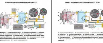
Generator connection diagram for VAZ 2107
The VAZ 2107 charging scheme depends on what type of generator is used. To recharge the battery on cars such as VAZ-2107, VAZ-2104, VAZ-2105, which have a carburetor engine, you will need a G-222 type generator or its equivalent with a maximum output current of 55A. In turn, VAZ-2107 cars with an injection engine use a generator 5142.3771 or its prototype, which is called a high-energy generator, with a maximum output current of 80-90A. It is also possible to install more powerful generators with an output current of up to 100A. Absolutely all types of alternating current generators have built-in rectifier units and voltage regulators; they are usually made in the same housing with brushes or are removable and mounted on the housing itself.
The VAZ 2107 charging circuit has minor differences depending on the year of manufacture of the car. The most important difference is the presence or absence of a charge indicator lamp, which is located on the instrument panel, as well as the method of connecting it and the presence or absence of a voltmeter. Such circuits are mainly used on carburetor cars, while on cars with injection engines the circuit does not change, it is identical to those cars that were manufactured previously.
Generator set designations:
- “Plus” of the power rectifier: “+”, V, 30, V+, WAT.
- “Ground”: “-”, D-, 31, B-, M, E, GRD.
- Excitation winding output: Ш, 67, DF, F, EXC, E, FLD.
- Output for connection to the serviceability lamp: D, D+, 61, L, WL, IND.
- Phase output:
Generator circuit VAZ-2107 type 37.3701
- Accumulator battery.
- Generator.
- Voltage regulator.
- Mounting block.
- Ignition switch.
- Voltmeter.
- Battery charge indicator lamp.
When the ignition is turned on, the plus from the lock goes to fuse No. 10, and then goes to the battery charge indicator lamp relay, then goes to the contact and to the coil output. The second terminal of the coil interacts with the central terminal of the starter, where all three windings are connected. If the relay contacts close, then the control lamp lights up. When the engine starts, the generator generates current and an alternating voltage of 7V appears on the windings. Current passes through the relay coil and the armature begins to attract, and the contacts open. Generator No. 15 passes current through fuse No. 9. Similarly, the excitation winding receives power through the brush voltage generator.
Generator g288e relay connection diagram
Chapter 3. ELECTRICAL EQUIPMENT OF VEHICLES
KamAZ-5320 and Ural-4320
Design and operation of the G288 car generator
KamAZ-5320 and Ural-4320
The generator is designed to operate in a single-wire electrical circuit of a vehicle. KamAZ 740 engines are equipped with a G288 generator operating with a voltage regulator 11.3702, or a G273-A generator set. The G288 alternating current generator (Fig. 3.2) with electromagnetic excitation is a three-phase twelve-pole electrical machine with a built-in rectifier using six silicon diodes. The rated power of the generator is 1000 W, rated voltage 28 V, rectified current not less than 47A. The generator has the following terminals: “+”—for connecting the batteries and load, “—”—for connecting to the vehicle ground, “W”—for connecting to the “VK” terminal of the instrument switch and starter and the “I/” terminal voltage regulator. The G273-A alternating current generator set consists of a generator, a built-in rectifier unit and an integrated voltage regulator YA-120M. Its rated voltage is 24 V, rated power is 800 W. The “+” terminal is used to connect the battery and load, and the “B” terminal is used to connect to the “VK” terminal of the instrument switch and starter. A seasonal adjustment switch is installed on the voltage regulator, which is carried out as follows: if the outside temperature remains stable at 0 °C and above, the screw is turned to the extreme left position, but if the outside temperature is set at 0 °C and below, the screw is turned to the extreme right position .
The generator consists of a stator, rotor, covers, rectifier block, and brush assembly. The field winding is located on a shaft that rotates on two ball bearings. At one end of the shaft there is a fan and a double-strand pulley, at the other there are slip rings connected to the excitation winding along which the brushes slide. The cover contains a rectifier block and a brush holder. The non-contact voltage regulator automatically maintains the generator voltage within limits that ensure battery charging and reliable operation of consumers.
Rice. 3.2. Generator: 1 - pulley; 2 - fan; 3, 9 — covers; 4 - stator; 5 - shaft; 6 - rotor; 7 — rectifier block; 8 — slip rings; 10—brush; 11 — brush assembly; 12—excitation winding; 13 - pole piece
Rice. 3.4. Connection diagram of current sources: O, I, II, III - position of the instrument switch and starter key; IV— to the torch switch; V— to the instrument and starter switch; VI - to the starter retractor relay; VII - to the heater electric motors; VIII - to the reversing lights; IX - to the thermal relay of the electric torch device; 1 - generator G272; 2 - contactor; 8— push-button “ground” switch; 4—mass switch VK.860; 5 - batteries; 6— PC530 starter relay; 7 - ammeter; 8 — instrument and starter switch VK353; 9 — fuse block; 10—relay-regulator PP356; 11—relay for disconnecting the generator excitation winding; Ch - black; B—white; 3—green; F - yellow; K - red; F - purple; Bark brown; O - orange
Source
Charging diagram for VAZ with injection engines
This scheme is identical to the schemes on other VAZ models. It differs from the previous ones in the method of exciting and monitoring the serviceability of the generator. It can be carried out using a special control lamp and a voltmeter on the instrument panel. Also, through the charge lamp, the generator is initially excited at the moment it starts working. During operation, the generator operates “anonymously,” that is, excitation comes directly from pin 30. When the ignition is turned on, power through fuse No. 10 goes to the charging lamp in the instrument panel. Then it goes through the mounting block to pin 61. Three additional diodes provide power to the voltage regulator, which in turn transmits it to the excitation winding of the generator. In this case, the indicator lamp will light up. It is at that moment when the generator operates on the plates of the rectifier bridge that the voltage will be much higher than that of the battery. In this case, the control lamp will not light up, because the voltage on its side on the additional diodes will be lower than on the side of the stator winding and the diodes will close. If the control lamp lights up while the generator is running, this may mean that additional diodes are broken.
Auto parts and service stations
Contact terminals (terminals, plug connectors, etc.) of generating sets of different models, years of manufacture and manufactured by different electrical manufacturers may have different letter, number or symbol designations. At the same time, not only a novice auto electrician or mechanic who is inexperienced in repairing on-board electrical network systems of cars, but even an experienced electrical equipment repair specialist may encounter unfamiliar designations, which can lead to unpleasant technical consequences during repairs and diagnostic checks of the generator.For those who are engaged in diagnosing and repairing electrical equipment only of domestic cars, it will not be difficult to remember the not so extensive list of symbols on the terminals of generators, but the contact connectors and terminals of generators of foreign cars often contain many unfamiliar symbols. It should be taken into account that sometimes the terminals and contacts of generators from individual manufacturers may have the same letter designation with different functionality.
Table 1 shows the most common designations of electrical contacts and terminals of generators, both domestic and foreign.
Table 1. Designation of contact connectors and terminals of generating sets
Terminal
| Functional purpose | Where to connect | |
| B+, 30, VAT | Battery (+) | Battery plus |
| E, B-, 31, “-”, GRD | (Earth – “earth”), Battery (-) | Battery minus |
| IN | (Battery) same as “S” (see below) | Battery plus |
| C,G | (Communication) control input for the voltage regulator by the engine control unit. When “-” is applied to this input, the voltage at the generator output will not exceed 12.5 V | |
| COM | (Communication) general name for the physical interface for control and diagnostics of the generator. The “BSD” (Bit Serial Device), “BSS” (Bit Synchronized) or “LIN” (Local Interconnect Network) protocols can be used. | Set-top box aRC-011, aVR-012 |
| G | For Honda vehicles with a square 4-pin connector, this means ignition (“IGNITION”) | |
| D+ | “+” terminal of an additional diode bridge to power the voltage regulator. Serves to connect an indicator lamp that supplies the initial excitation voltage and indicates the operability of the generator | Warning lamp |
| L, I, IL, 61, W, IND | (Lamp/Indicator/Illumination) output to the generator health indicator lamp (usually after the “plus” of the additional rectifier, where there is one) | Warning lamp |
| D | (Drive) regulator control input with terminal P-D generators (Mazda cars) and Hitachi (Kia Sephia cars 1997-2000) | Set-top box aRC-011, aVR-012 |
| D | (Dummy) empty, no connection; found on Japanese cars | |
| 0, MP | Stator winding zero point output | |
| F, DF, FLD, 67, Ш, EXC | (Field) voltage regulator output (excitation winding output) | External regulator |
| FR, DFM, M | (Field Report/Digital Field Monitor/Monitor) output for monitoring the load on the generator by the engine control unit | Attachment aRC-011, aVR-012 or VRT-RC |
| LI | (Load Indicator) the same as “FR”, only the signal is inverted | Attachment aRC-011 or VRT-RC |
| IG, A, 15, B | (Ignition) ignition switch input | Battery plus |
| LIN | Direct indication of the generator control and diagnostic interface via the “LIN” (Local Interconnect Network) protocol | Attachment aRC-011 |
| N | (NULL) output of the middle stator winding. Typically used to control the health indicator lamp of a generator with a mechanical voltage regulator | |
| N/C | (no connect) no connection | |
| P, S, STA, Stator, R | (Phase/Stator) output from one of the generator stator windings. Serves to determine the excited state of the generator by the voltage regulator | |
| W | (Wave) output from one of the stator phase windings for connecting a tachometer (usually this output is used in cars with diesel engines) | |
| RLO | (Regulated Load Output) voltage control input for stabilizing the regulator in the range of 11.8…15 V (Toyota cars) | Attachment aRC-011 |
| RVC(L) | (Regulated Voltage Control) similar to “SIG”, only the voltage range is 11.0…15.5 V. The control signal is supplied to the “L” terminal | Attachment aRC-011 or VRT-RC |
| S, AS, BVS | (Sense/Alternator Sense/Battery Voltage Sense) sensor, input for comparing voltage at the control point. Typically the test point is located in the fuse box closest to the battery ("CHARGE" fuse). | Battery plus |
| S.I.G., R.C. | (Signal/Regulator Control) voltage code input (same as “D”) | Attachment aRC-011 or VRT-RC |
| D | (Digital) voltage code input on Ford vehicles (same as SIG) | Set-top box aRC-011, aVR-012 |
Click on image to enlarge
Below is an additional list of designations that may not have been included in the table above: A - the same as IG plus battery; AS (Alternator Sense) - the same as S - battery plus; B+ battery - (+) battery plus; B- battery - (-) minus battery; BVS (Battery Voltage Sense) - the same as S - battery plus; C (Communication) control input for the voltage regulator of the engine control unit. When <-> is applied to this input, the voltage at the generator output will not exceed 12.5 V; COM (Communication) is a general designation for the physical interface for control and diagnostics of the generator. BSD (Bit Serial Device), BSS (Bit Synchronized Signal) or LIN (Local Interconnect Network) protocols can be used; prefix aRCI 011; D+ - terminal (+) of an additional diode bridge to power the voltage regulator. Serves to connect an indicator lamp that supplies the initial excitation voltage and indicates the operation of the generator; the indicator lamp; D (Drive) — regulator control input with PD terminal; aRC-011 or VRT-RC attachment; D (Dummy) - empty, no connection, mainly on Japanese cars; D (Digital) - voltage code input on American Fords, the same as SIG; DF - same as F external regulator; DFM (Digital Field Monitor) - same as FR; aRC-011 or VRT-RC attachment; E (Earth) “ground”, battery (-); F (Field) - voltage regulator output external regulator; FLD - same as F external regulator; FR (Field Report) - output for monitoring the load on the generator by the engine control unit; G (Ground) - same as C; I (Indicator) - the same as L control lamp; IG (Ignition) - ignition switch input plus battery; IL (Illumination) is the same as L indicator lamp; L (Lamp) - output to the lamp of the generator performance indicator; control lamp; LI (Load Indicator) - the same as FR, only the signal is inverted; LIN direct indication of the control and diagnostic interface of the generator via the LIN (Local Interconnect Network) protocol; M (Monitor) - same as FR; N (NULL) - output of the midpoint of the stator windings. Typically used to control the health indicator lamp of a generator with a mechanical voltage regulator; N/C (no connect) - no connection; P (Phase) output from one of the generator stator windings. Serves to determine the excited state of the generator by the voltage regulator; RC (Regulator Control) - same as SIG; RLO (Regulated Load Output) - voltage control input for stabilizing the regulator in the range 11.8-15 V (Toyota) RVC (L) (Regulated Voltage Control) - similar to SIG; S (Sense) - sensor, input for comparing voltage at the control point. Typically the test point is in the fuse box closest to the battery (CHARGE fuse) plus the battery; S (Stator) - same as P; SIG (Signal) - voltage code input; STA (Stator) - same as P; Stator - same as P; W (Wave) - output from one of the generator stator windings for connecting a tachometer in cars with diesel engines; 15 - the same as IG plus battery; 30 - the same as B+ plus battery; ; 31 - the same as B- battery minus 4 61 - the same as L control lamp; 67 - the same as F. Addition: P, S, STA, Stator, R Phase/Stator output from one of the generator stator windings. Serves to determine the excited state of the generator by the voltage regulator
Source: kat.ru.
Checking generator operation
You can check the functionality of the generator in several ways using certain methods, for example: you can check the output current of the generator, the voltage drop on the wire that connects the current output of the generator to the battery, or check the regulated voltage.
To check, you will need a multimeter, a car battery and a lamp with soldered wires, wires for connecting between the generator and the battery, and you can also take a drill with a suitable head, since you may have to twist the rotor by the nut on the pulley.
Basic check with a light bulb and multimeter
Connection diagram: output terminal (B+) and rotor (D+). The lamp must be connected between the main output of the generator B+ and contact D+. After this, we take the power wires and connect the “minus” to the negative terminal of the battery and to the generator ground, the “plus”, respectively, to the plus of the generator and to the B+ output of the generator. We fix it on a vice and connect it.
We turn on the tester in DC mode, attach one probe to the battery to “plus”, and the second one too, but to “minus”. Next, if everything is in working order, then the light should light up, the voltage in this case will be 12.4V. Then we take a drill and start turning the generator, accordingly, the light bulb will stop burning at this moment, and the voltage will already be 14.9V. Then we add a load, take an H4 hologen lamp and hang it on the battery terminal, it should light up. Then we connect the drill in the same order and the voltage on the voltmeter will show 13.9V. In passive mode, the battery under the light bulb gives 12.2V, and when we turn it with a drill, it gives 13.9V.
Generator test circuit
Strictly not recommended:
- Check the functionality of the generator by short circuit, that is, “to spark”.
- It is also undesirable to allow the generator to operate without consumers turned on; it is also undesirable to operate with the battery disconnected.
- Connect terminal “30” (in some cases B+) to ground or terminal “67” (in some cases D+).
- Carry out welding work on the car body with the generator and battery wires connected.
Schematic electrical diagrams, connecting devices and pinouts of connectors
The generator in cars is designed to generate electricity and charge the battery. If the normal operation of a car electric generator is disrupted, the battery begins to discharge and soon the car will stop starting completely - there is not enough battery charge. This device consists of a three-phase diode bridge, which, in turn, has 6 silicon diodes. Electrical voltage is created by the excitation of the rectifier at the moment when the rotor poles change under the stator windings. When the rotor rotates inside the machine stator, the poles of the rotor change. To increase the value of magnetic fluxes, the stator contains an electromagnetic exciting winding in the area of the magnetic cores. Marking and designation of wires:
- P - pink.
- F - purple.
- O - orange.
- B&W - black and white.
- KB - brown and white.
- CHG - black and blue.
- K - brown.
- H - black.
- B - white.
Connection diagram for the VAZ-2101 generator
Structurally, generator 2101 consists of the following main elements:
- The rotor is a moving part that rotates from the engine crankshaft. Has an excitation winding.
- The stator is the stationary part of the generator and also has a winding.
- Front and rear covers , inside of which bearings are installed. They have eyelets for attaching to the internal combustion engine. The back cover contains a capacitor necessary to cut off the alternating current component.
- Semiconductor bridge - called a “horseshoe” for its similarity. Three pairs of semiconductor power diodes are mounted on a horseshoe-shaped base.
- A pulley on which the VAZ-2101 generator belt is placed. The belt is V-shaped (on modern cars a multi-ribbed belt is used).
- The voltage regulator is installed in the engine compartment, away from the generator. But still it must be considered part of the structure.
- The brushes are mounted inside the generator and transmit the supply voltage to the field winding (on the rotor).
Connection diagram for the VAZ-2107 generator
1 - battery; 2 - negative diode; 3 - additional diode; 4 - generator; 5 - positive diode; 6 - stator winding; 7 - voltage regulator; 8 — rotor winding; 9 — capacitor for suppressing radio interference; 10 — mounting block; 11 — battery charge indicator lamp in the instrument cluster; 12 - voltmeter; 13 — ignition relay; 14 - ignition switch.
Not available:
| № | Part code | Name | Part Information |
| G287-3701301 | Slip ring side cover | Quantity for 236 M 2) 238 M 3) 238 AM 4) 238 GM 5) 238 IM 6) 238 ND 7) 238 N 238 L 9) 238 PM 10) 238 FM 1 Model G287 Group Electrical equipment Subgroup Generator Serial number of the part 301 | Not available |
| G287-3701307 | Sealing gasket | Quantity for 236 M 2) 238 M 3) 238 AM 4) 238 GM 5) 238 IM 6) 238 ND 7) 238 N 238 L 9) 238 PM 10) 238 FM 1 Model G287 Group Electrical equipment Subgroup Generator Serial number of the part 307 | Not available |
| G272-3701010-01 | Brush holder assembly | Quantity for 236 M 2) 238 M 3) 238 AM 4) 238 GM 5) 238 IM 6) 238 ND 7) 238 N 238 L 9) 238 PM 10) 238 FM 1 Model G272 Group Electrical equipment Subgroup Generator Serial number of the part 010 | Not available |
| G272-3701011 | Brush holder | Quantity for 236 M 2) 238 M 3) 238 AM 4) 238 GM 5) 238 IM 6) 238 ND 7) 238 N 238 L 9) 238 PM 10) 238 FM 1 Model G272 Group Electrical equipment Subgroup Generator Serial number of the part 011 | Not available |
| G272-3701020-A | Brush assembly | Quantity for 236 M 2) 238 M 3) 238 AM 4) 238 GM 5) 238 IM 6) 238 ND 7) 238 N 238 L 9) 238 PM 10) 238 FM 1 Model G272 Group Electrical equipment Subgroup Generator Serial number of the part 020 Additionally Interchangeable with a part released earlier under the same number | Not available |
| G272-3701030-A | Brush assembly | Quantity for 236 M 2) 238 M 3) 238 AM 4) 238 GM 5) 238 IM 6) 238 ND 7) 238 N 238 L 9) 238 PM 10) 238 FM 1 Model G272 Group Electrical equipment Subgroup Generator Serial number of the part 030 Additionally Interchangeable with a part released earlier under the same number | Not available |
| G272-3701012-A | Brush holder cover | Quantity for 236 M 2) 238 M 3) 238 AM 4) 238 GM 5) 238 IM 6) 238 ND 7) 238 N 238 L 9) 238 PM 10) 238 FM 1 Model G272 Group Electrical equipment Subgroup Generator Serial number of the part 012 Additionally Interchangeable with a part released earlier under the same number | Not available |
| 8Х-1497-А | Washer | Quantity per 236 M 2) 238 M 3) 238 AM 4) 238 GM 5) 238 IM 6) 238 ND 7) 238 N 238 L 9) 238 PM 10) 238 FM 5 | Not available |
| M11-41081 | Spring washer | Quantity per 236 M 2) 238 M 3) 238 AM 4) 238 GM 5) 238 IM 6) 238 ND 7) 238 N 238 L 9) 238 PM 10) 238 FM 2 | Not available |
| G250E1-3701016 | Bolt | Quantity for 236 M 2) 238 M 3) 238 AM 4) 238 GM 5) 238 IM 6) 238 ND 7) 238 N 238 L 9) 238 PM 10) 238 FM 2 Model G250E1 Group Electrical equipment Subgroup Generator Serial number of the part 016 | Not available |
| 8Х-1537М | screw | Quantity per 236 M 2) 238 M 3) 238 AM 4) 238 GM 5) 238 IM 6) 238 ND 7) 238 N 238 L 9) 238 PM 10) 238 FM 2 | Not available |
| МХ-0246-01 | Spring washer 8 | Quantity per 236 M 2) 238 M 3) 238 AM 4) 238 GM 5) 238 IM 6) 238 ND 7) 238 N 238 L 9) 238 PM 10) 238 FM 2 | Not available |
| 1MU-37 | Washer | Quantity per 236 M 2) 238 M 3) 238 AM 4) 238 GM 5) 238 IM 6) 238 ND 7) 238 N 238 L 9) 238 PM 10) 238 FM 1 | Not available |
| G287-3701319 | Insulating sleeve | Quantity for 236 M 2) 238 M 3) 238 AM 4) 238 GM 5) 238 IM 6) 238 ND 7) 238 N 238 L 9) 238 PM 10) 238 FM 1 Model G287 Group Electrical equipment Subgroup Generator Serial number of the part 319 | Not available |
| NO-0801-10 | Contact bolt | Quantity per 236 M 2) 238 M 3) 238 AM 4) 238 GM 5) 238 IM 6) 238 ND 7) 238 N 238 L 9) 238 PM 10) 238 FM 1 | Not available |
| G287-3701305-A | O-ring contact ring | Quantity for 236 M 2) 238 M 3) 238 AM 4) 238 GM 5) 238 IM 6) 238 ND 7) 238 N 238 L 9) 238 PM 10) 238 FM 1 Model G287 Group Electrical equipment Subgroup Generator Serial number of the part 305 Additionally Interchangeable with a part previously released under the same number | Not available |
| G21-3701005 | Rotor cup | Quantity per 236 M 2) 238 M 3) 238 AM 4) 238 GM 5) 238 IM 6) 238 ND 7) 238 N 238 L 9) 238 PM 10) 238 FM 1 Model G21 Group Electrical equipment Subgroup Generator Serial number of the part 005 | Not available |
| G288-3701100-A | Stator | Quantity for 236 M 2) 238 M 3) 238 AM 4) 238 GM 5) 238 IM 6) 238 ND 7) 238 N 238 L 9) 238 PM 10) 238 FM 1 Model G288 Group Electrical equipment Subgroup Generator Serial number of the part 100 Additionally Interchangeable with a part released earlier under the same number | Not available |
| G210-3701202 | Split ring | Quantity for 236 M 2) 238 M 3) 238 AM 4) 238 GM 5) 238 IM 6) 238 ND 7) 238 N 238 L 9) 238 PM 10) 238 FM 1 Model G210 Group Electrical equipment Subgroup Generator Serial number of the part 202 | Not available |
| G288-3701200 | Rotor | Quantity for 236 M 2) 238 M 3) 238 AM 4) 238 GM 5) 238 IM 6) 238 ND 7) 238 N 238 L 9) 238 PM 10) 238 FM 1 Model G288 Group Electrical equipment Subgroup Generator Serial number of the part 200 | Not available |
| 7X-4066 | Screw | Quantity per 236 M 2) 238 M 3) 238 AM 4) 238 GM 5) 238 IM 6) 238 ND 7) 238 N 238 L 9) 238 PM 10) 238 FM 4 | Not available |
| X-4001-01 | Spring washer | Quantity per 236 M 2) 238 M 3) 238 AM 4) 238 GM 5) 238 IM 6) 238 ND 7) 238 N 238 L 9) 238 PM 10) 238 FM 11 | Not available |
| 15Х-4148 | Key | Quantity per 236 M 2) 238 M 3) 238 AM 4) 238 GM 5) 238 IM 6) 238 ND 7) 238 N 238 L 9) 238 PM 10) 238 FM 1 | Not available |
| G287-3701405 | Special washer | Quantity for 236 M 2) 238 M 3) 238 AM 4) 238 GM 5) 238 IM 6) 238 ND 7) 238 N 238 L 9) 238 PM 10) 238 FM 1 Model G287 Group Electrical equipment Subgroup Generator Serial number of the part 405 | Not available |
| G287-3701053 | Spacer sleeve | Quantity for 236 M 2) 238 M 3) 238 AM 4) 238 GM 5) 238 IM 6) 238 ND 7) 238 N 238 L 9) 238 PM 10) 238 FM 1 Model G287 Group Electrical equipment Subgroup Generator Serial number of the part 053 | Not available |
| G288-3701130 | Stator phase | Quantity for 236 M 2) 238 M 3) 238 AM 4) 238 GM 5) 238 IM 6) 238 ND 7) 238 N 238 L 9) 238 PM 10) 238 FM 1 Model G288 Group Electrical equipment Subgroup Generator Serial number of the part 130 | Not available |
| G288-3701132 | Stator phase | Quantity for 236 M 2) 238 M 3) 238 AM 4) 238 GM 5) 238 IM 6) 238 ND 7) 238 N 238 L 9) 238 PM 10) 238 FM 1 Model G288 Group Electrical equipment Subgroup Generator Serial number of the part 132 | Not available |
| МХ-0235-01 | screw | Quantity per 236 M 2) 238 M 3) 238 AM 4) 238 GM 5) 238 IM 6) 238 ND 7) 238 N 238 L 9) 238 PM 10) 238 FM 1 | Not available |
| G287-3701074 | Washer | Quantity for 236 M 2) 238 M 3) 238 AM 4) 238 GM 5) 238 IM 6) 238 ND 7) 238 N 238 L 9) 238 PM 10) 238 FM 1 Model G287 Group Electrical equipment Subgroup Generator Serial number of the part 074 | Not available |
| G288-3701051 | Generator pulley G-288E | Quantity for 236 M 2) 238 M 3) 238 AM 4) 238 GM 5) 238 IM 6) 238 ND 7) 238 N 238 L 9) 238 PM 10) 238 FM 1 Model G288 Group Electrical equipment Subgroup Generator Serial number of the part 051 | Not available |
| G287-3701055 | Fan | Quantity for 236 M 2) 238 M 3) 238 AM 4) 238 GM 5) 238 IM 6) 238 ND 7) 238 N 238 L 9) 238 PM 10) 238 FM 1 Model G287 Group Electrical equipment Subgroup Generator Serial number of the part 055 | Not available |
| G287-3701400 | Drive side cover assembly | Quantity for 236 M 2) 238 M 3) 238 AM 4) 238 GM 5) 238 IM 6) 238 ND 7) 238 N 238 L 9) 238 PM 10) 238 FM 1 Model G287 Group Electrical equipment Subgroup Generator Serial number of the part 400 | Not available |
| G288A-3701051 | Generator pulley G-287E | Quantity per 236 M 2) 238 M 3) 238 AM 4) 238 GM 5) 238 IM 6) 238 ND 7) 238 N 238 L 9) 238 PM 10) 238 FM 1 Model G288A Group Electrical equipment Subgroup Generator Serial number of the part 051 | Not available |
| G287-3701054 | Sleeve | Quantity for 236 M 2) 238 M 3) 238 AM 4) 238 GM 5) 238 IM 6) 238 ND 7) 238 N 238 L 9) 238 PM 10) 238 FM 1 Model G287 Group Electrical equipment Subgroup Generator Serial number of the part 054 | Not available |
| 6-1180304K1S9 | Single row radial ball bearing with double-sided seal 20x52x18 | Quantity for 236 M 2) 238 M 3) 238 AM 4) 238 GM 5) 238 IM 6) 238 ND 7) 238 N 238 L 9) 238 PM 10) 238 FM 1 Model 6 Group Engine power system Subgroup 1180 Ordinal part number 304 Optional Interchangeable with a previously released part under the same number | Not available |
| 6-180603K1S9 | Single row radial ball bearing with double-sided seal 20x52x18 | Quantity per 236 M 2) 238 M 3) 238 AM 4) 238 GM 5) 238 IM 6) 238 ND 7) 238 N 238 L 9) 238 PM 10) 238 FM 1 Burnished coating | Not available |
| MX-0139 | Screw | Quantity per 236 M 2) 238 M 3) 238 AM 4) 238 GM 5) 238 IM 6) 238 ND 7) 238 N 238 L 9) 238 PM 10) 238 FM 3 | Not available |
| X-1482-01 | Spring washer | Quantity per 236 M 2) 238 M 3) 238 AM 4) 238 GM 5) 238 IM 6) 238 ND 7) 238 N 238 L 9) 238 PM 10) 238 FM 6 | Not available |
| NO-0102 | M6 screw | Quantity per 236 M 2) 238 M 3) 238 AM 4) 238 GM 5) 238 IM 6) 238 ND 7) 238 N 238 L 9) 238 PM 10) 238 FM 3 | Not available |
| X-4237-01 | M5 screw | Quantity per 236 M 2) 238 M 3) 238 AM 4) 238 GM 5) 238 IM 6) 238 ND 7) 238 N 238 L 9) 238 PM 10) 238 FM 4 | Not available |
| G250-3701053-A1 | Bracket | Quantity for 236 M 2) 238 M 3) 238 AM 4) 238 GM 5) 238 IM 6) 238 ND 7) 238 N 238 L 9) 238 PM 10) 238 FM 1 Model G250 Group Electrical equipment Subgroup Generator Serial number of the part 053 Additionally Interchangeable with a part released earlier under the same number | Not available |
| G287-3701060 | Lid | Quantity for 236 M 2) 238 M 3) 238 AM 4) 238 GM 5) 238 IM 6) 238 ND 7) 238 N 238 L 9) 238 PM 10) 238 FM 1 Model G287 Group Electrical equipment Subgroup Generator Serial number of the part 060 | Not available |
Connection diagram for the VAZ-2108 generator
The VAZ-2108 generator has a rather massive stator winding, since it uses a large cross-section wire. It is with its help that electricity is generated. The wire is wound evenly over the entire inner surface of the stator into recesses specially provided for this purpose in the magnetic core. It’s worth talking about the latter separately. The middle part, the generator stator, consists of a series of thin metal plates pressed tightly together. They are often boiled on the outside to prevent separation.
Connection diagram for the VAZ-2109 generator
- Alternator. The 37.3701 or 94.3701 series can be installed.
- Negative diode.
- Additional diode.
- Positive diode.
- Alternator warning lamp, also known as battery discharge lamp.
- Instrument cluster.
- Voltmeter.
- Relay and fuse box located in the engine compartment in the compartment between the engine and the vehicle interior.
- Additional resistors built into the fuse mounting block.
- Ignition relay.
- Egnition lock.
- Accumulator battery.
- Capacitor.
- Rotor winding.
- The voltage relay is located in the engine compartment.
Generator g288e relay connection diagram
Bibliographic link to the article:
Gumelev V.Yu., Parkhomenko A.V., Rogachev V.D. Interchangeability, applicability and design of the G 288E generator // Modern technology and technology. 2013. No. 2 [Electronic resource]. URL: https://technology.snauka.ru/2013/02/1663 (access date: 04/12/2021).
The Ural-4320-31 vehicle is equipped with a generator G 288E or 1702.3771. In addition to these generators, their analogues can be installed according to Table 1. The appearance and structure of the automobile alternator G 288E is presented in accordance with Figure 2.
Table 1 – Main technical characteristics of generators interchangeable with generators 1702.3771 and G 288E
1 – pulley; 2 – fan impeller; 3 – front cover; 4 – stator;
5 – back cover; 6 – output L1 (alternating phase voltage); 7 – brush holder with brushes; 8 – output “ + ” of the generator
Figure 1 – Generator G 288E
According to Table 2, its main characteristics are presented.
Table 2 – Main characteristics of the G 288E generator
| Rated voltage | IN | 28 |
| Load current rated | A | 47 |
| Rated power | W | 1000 |
| Rotor speed at 28 V: |
— with a load current of no more than 30 A min -1
Maximum rotation speed min -1 8000 Excitation current A from 1.5 to 1.7 Generator weight without pulley kg 10 Length mm 230 Diameter mm 174 Applicability vehicles with YaMZ-236, YaMZ-238 engines; KamAZ-4310 vehicles with 740.10 engine.
Connection diagram for the VAZ-2110 generator
On VAZ-2110, 2111 and 2112 cars, a 94.3701 generator was installed with a maximum output current of 80 Amperes and a voltage = 13.2–14.7 Volts.
Here is a breakdown of the connection diagram for the generator on the ten :
- Battery 12V;
- generator 94.3701;
- mounting block;
- egnition lock;
- battery charge indicator lamp in the instrument cluster
How to check the generator yourself
How to check a VAZ generator using the example of model 2109. Generator type 94.3701 alternating current, three-phase, with a built-in rectifier unit and an electronic voltage regulator, right-hand rotation.
Generator connection diagram . The voltage to excite the generator when the ignition is turned on is supplied to terminal “D+” of the regulator (terminal “D” of the generator) through indicator lamp 4 located in the instrument cluster. After starting the engine, the excitation winding is powered by three additional diodes installed on the generator rectifier block. The operation of the generator is controlled by a warning lamp in the instrument cluster. When the ignition is turned on, the lamp should be on, and after starting the engine, it should go out if the generator is working. If the lamp is brightly lit or glows half-lit, it indicates a malfunction.
The “minus” of the battery should always be connected to ground, and the “plus” should always be connected to the “B+” terminal of the generator. Failure to turn the battery back on will immediately cause increased current through the generator valves and damage them.
It is not allowed to operate the generator with the battery disconnected. This will cause short-term overvoltages to occur at the “B+” terminal of the generator, which can damage the generator voltage regulator and electronic devices in the vehicle’s on-board network.
It is prohibited to check the functionality of the generator “for spark” even by briefly connecting the “B+” terminal of the generator to ground. In this case, significant current flows through the valves and they are damaged.
Alternating current generator set G-273-A, shown in Fig. 1, consists of a generator, a built-in rectifier unit and an integrated voltage regulator of the Y-120M brand. Its rated voltage is 24 V, rated power is 800 W. The “+” terminal is used to connect the battery and load, and the B terminal is used to connect to the VK terminal - the instrument switch and starter.
The voltage regulator has a seasonal adjustment switch. The adjustment is performed as follows: if the air temperature remains steadily above 0 °C, the screw is turned to the extreme left position (J7), but if the outside temperature is set at 0 °C and below, the screw is turned to the extreme right position (3).
The G-288 alternating current generator with electromagnetic excitation is a three-phase twelve-pole electrical machine with a built-in rectifier using six silicon diodes. The rated power of the generator is 1000 W, the rated voltage is 28 V, the rectified current is not less than 47 A. The generator has the following terminals: ( + ) - for connecting batteries and load: (-) - for connecting to the vehicle ground; Ш - for connection to the VK terminal of the instrument switch and starter and the Ш terminal of the voltage regulator.
Generator malfunctions and ways to eliminate them. When entering for repair, the generator may have various malfunctions.
Before removing the generator from the engine or before installing it on the engine, be sure to disconnect the battery, since the positive terminal (+) of the generator is energized.
To remove the generator, loosen the coupling bolt of the generator bracket support, unscrew the nut of the stud securing the generator to the bracket, and unscrew the bolt securing the generator to the tension bar.
Rice. 1. Generator set G-273 A: a - electrical diagram; b - section; c - voltage regulator; 1 – pulley; 2 - fan; 3 — drive side cover; 4 - stator; 5 - rotor; 6- rotor shaft; 7 - rectifier block; 8—cover from the side of the slip rings; 9 — slip ring; 10 — bearing cover; 11 — make-up resistor; 12 - voltage regulator I 12 ohm; 13 — brush holder; 14 - seasonal adjustment switch; 15 - seasonal adjustment resistor; D - connection terminal with make-up resistor; C - connection terminal with all-season adjustment resistor; Ш – connection terminal with the rotor winding; conclusions: ( + ) - connection of the battery and load; B - for connection to the terminal of the VC switch of devices and starter; ( — ) — connection to the vehicle ground; L — position at temperatures above 0 °C; 3 - position at temperatures below 0 ° C
Rice. 2. Test bench 532M:
The parts and components of the generator after disassembly are divided into two groups: parts without windings and parts with windings.
Parts that do not have windings are washed with Labomid-203 solution.
Parts with windings are cleaned with a rag soaked in gasoline, blown with compressed air and dried in an oven at a temperature of 90...100 °C for 45-90 minutes.
Cleaned parts and assemblies are subjected to defect detection. Parts with mechanical damage are replaced. Bent fan blades are adjusted and straightened. The wear of the pulley grooves is checked by installing rollers with a diameter of 14 mm into the pulley and checking the size by the protrusions of the rollers. The size between the roller protrusions must be at least 83.5 mm. Worn mounting holes for the bearing in the cover on the drive side are bored and then repair rings with an internal diameter equal to the nominal one are pressed into them.
The generator rotor may have the following defects: wear of the iron pole pieces as a result of contact with the iron of the stator; wear of the shaft journals for ball bearings; bent armature shaft; wear of slip rings; runout of slip rings relative to the shaft journals; damage or burning of the rotor winding wire insulation; short circuit of winding turns to ground or to each other; break of the rotor winding from the slip rings.
The serviceability of the rotor field winding is checked with an ohmmeter or tester. The resistance value must correspond to that specified in the technical specifications if there are no short-circuited turns in the winding. If there is a break in the winding, then the ohmmeter needle does not deviate.
The serviceability of the windings and the reliability of the fit of the brushes in the slip rings are checked on the stand according to the diagram shown in Fig. 2.
When the voltage of the DC power source is 28 V, connected to the output ends of the winding, the amount of current consumed should not exceed the values specified in the technical specifications of the generator.
The short circuit of the excitation winding to ground is determined with a test lamp at a voltage of 220-550 V. If the lamp does not light up within a minute, then the winding insulation is in good condition.
The generator stator with coils may have the following defects: wear of the stator iron as a result of scuffing of the pole pieces; damage or burning of the insulation of the winding wire of the stator phase coil; short circuit of coil turns to ground or to each other; breakage of the output ends of the phase coils; damage or burning of the insulation of the output ends.
The stator winding is checked separately after disassembling the generator with the winding terminals disconnected from the rectifier unit. A break in the stator phase winding is detected by alternately connecting two phases to an ohmmeter or tester or connecting through a test lamp to a current source with a voltage of 12-30 V. If the winding is working properly, the ohmmeter readings should correspond to the values specified in the technical specifications.
In the event of a break in one of the windings, when connecting it to the terminals of the other two, the ohmmeter or tester needle does not deviate (the test lamp does not light up).
The interturn short circuit of the stator winding is checked using a flaw detector model PDO-1.
The brush holder may have the following defects: wear of the brushes in height; loss of brush spring stiffness; cracks and breaks in the brush holder cover; breaks and cracks on the brush holder body.
The height of the brushes in accordance with the requirements of the technical specifications for control, sorting and restoration should be (15±0.5) mm. If the brush height is less than 14.5 mm, the brushes must be replaced. The loss of spring stiffness is determined by the height on the device under a load of (220±30) g. If the height is less than 17.5 mm, the springs are replaced with new ones. Cracks and breaks on the body and brush holder cover are not allowed. Housings and covers that have cracks or breaks are replaced with new ones.
Assembly, running-in and testing of generators. When assembling the generator, the beginning of the phases of the stator coils must be stripped at a length of (16±3) mm, twisted, welded or soldered with POS-40 solder at a length of at least 6 mm and insulated with a PVC tube. Inter-coil connections should be braided and secured to the front parts of the coils by 15 mm. The stator is impregnated with ML 92 or GF 95 varnish with the addition of 15% K-421-02 grade resin.
The resistance of the excitation coil at a temperature of 20 °C must be at least 16.5-0.50 Ohm. After installing the coil between the poles, it is necessary to check it for the absence of interturn short circuits and short circuits to ground. The distance between the opposite poles of the left and right halves of the rotor should not be less than 3.5 mm. The leads of the excitation coil should be placed in the groove and soldered to the slip rings with POS-40 solder.
The diameter of the slip rings should be 31.0-29.3 mm. The permissible runout of slip rings and poles relative to the journals for ball bearings is 0.08 mm.
Roughness of the surface of the rotor journals under the internal rings - set the voltmeter switch to the “RN” position; set the excitation switch to the “CPP” position.
3. Check the constancy of the generator voltage without load (idling), in this case it is necessary: - set the load regulator handle to the “min” position (in the direction of the arrow), and the speed change flywheel to the extreme left position; — press the “start” button, after pressing the “start” button, the three-phase current generator installed on the frame inside the stand is turned on; — using the flywheel to change the rotation speed of the drive shaft of the V-belt drive stand, set the rotation speed of the generator armature shaft to 2,000 min; at a generator shaft speed of 2,000 min-1, the generator should produce a voltage f/ - 27.6-28.8 V;
the voltage is controlled using the stand's voltmeter:
4. Check the generator under load to determine the maximum current value, for this it is necessary: - use the flywheel of the V-belt drive to set the rotation speed of the stand’s drive shaft to 2000-3000 min-1; in this case, the generator should produce a voltage U = 27.6-28.8 V; — use the load rheostat handle to set the maximum load on the generator; in this case, the stand ammeter needle should show a current strength of 15-20 A at U = const.
In addition, the quiet operation of the mechanical part of the generator is checked.
Acceptance of generators by Quality Control Department is carried out during or after testing through external inspection, listening to tfx operation and monitoring performance characteristics. In this case they check:
availability of all external parts in accordance with the drawings; absence of mechanical damage and noisy operation; compliance of the operating characteristics of the generator with the requirements of the “Technical Conditions for Assembly and Testing”.
Valid generators accepted by the quality control department must have an acceptance stamp.