Category: KAMAZ
- Feasibility of application
- Power steering components
- Power steering KamAZ 4310 device and adjustment
- Performance indicators
- Causes and symptoms of malfunctions
- Pumping the hydraulic booster KamAZ 4310
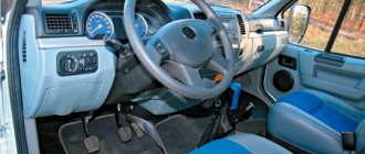
The weight of the truck reaches fifteen tons, it is difficult to imagine how the average person would drive such a “block” if not for the KamAZ 4310 power steering. For this reason, vehicles produced at the Kama plant are equipped with a similar mechanism.
Most users are accustomed to this fact and perceive power steering as a “proper” feature. However, do not forget that the mechanism requires care and attention, since the laws of physics also affect it. The key to trouble-free operation, the hydraulic component. Elimination of emergency situations associated with air entering the circuit is the main problem affecting the correct operation of the unit.
Compliance with the rules and requirements will make it easier to operate the truck, minimize the force applied to the steering wheel, reduce fatigue, and make it safer to drive on the road.
KamAZ-4310:
How to check KAMAZ power steering
First, it is necessary to evaluate the condition of the wheel balancing, the air pressure inside the tires, the adjustment of the wheel bearings, and the functioning of the shock absorbers.
Be sure to check the oil content inside the pump reservoir. You need to make sure that there is no air or dirt inside. The absence of oil leaks is also checked.
The force of the steering wheel is measured by a dynamometer attached to the wheel rim in three options relative to the position of the latter:
- When the steering wheel is turned more than two turns compared to the middle position, the force on it should be from 5.9 to 15.7 newtons. In this situation, the engagement with the ball screw is located in a position that is close to the extreme, with almost complete exclusion of friction, and the magnitude of the force is determined mainly through the friction moment of the bearings for the stop and the power steering seals. When the wheel rim force does not match the specified value, this indicates that the screw bearings are incorrectly (too tightly or too loosely) tightened or indicates damage to the ball nut. If the tightening is insufficient, the vehicle's directional stability deteriorates, and if it is over-tightened, in addition to damaging the ball nut, the steering mechanism jams.
- When the said wheel is turned three-quarters of a turn from its center position, the force must not exceed 22.6 and not be less than 19.6 newtons. In this position, friction occurs in the ball screw and is caused by preload. In the case when the force deviates from the above figures, damage to this pair can be stated.
- When this wheel is located in the middle position, the force on it should be 3.9-5.9 newtons higher than the force that is obtained if measured in the 2nd position described above, but should also not exceed 21.8 newtons. In such a situation, the power steering engagement adjustment is checked. When the force is insufficient compared to the above value, the clearance in the engagement exceeds the permissible level, and when it exceeds this value, this indicates that the clutch is over-tightened, which leads, among many reasons, to unsatisfactory self-return of the wheels to the center position. When the forces in the above positions do not correspond to the described values, the hydraulic booster should be adjusted.
Spare parts for Ural, Kraz, MAZ, Kamaz trucks. Engine parts YaMZ-236, YaMZ-238
__________________________________________________________________________
__________________________________________________________________________
Repair and adjustment of Kamaz power steering
__________________________________________________________________
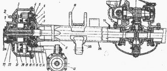
The operation of the power steering (power steering) of Kamaz-4310, 43114, 43118, Kamaz-5320, 53212, 53215, Kamaz-55111, 55102, 5511, Kamaz-5410, 54115 vehicles is carried out as follows. When moving in a straight line, screw 15 (Fig. 1) and spool 20 are in the middle position. The injection lines 26 and drain 32, as well as both cavities 7 and 25 of the hydraulic cylinder are connected.
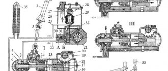
Fig.1. Scheme of operation of the power steering Kamaz-4310, 43114, 43118, Kamaz-5320, 53212, 53215, Kamaz-55111, 55102, 5511, Kamaz-5410, 54115 1 - steering wheel; 2 — spring of the hydraulic system filter safety valve; 3 - filter; 4 — power steering pump; 5 — bypass valve; 6 — bipod shaft with gear sector; 7 — rear cavity of the hydraulic booster; 8 — piston-rack; 9 — bipod; 10 — longitudinal thrust; 11 - Transverse rod; 12 — front wheel of the car; 13 – magnetic plug; 14 — ball nut; 15 - screw; 16 — steering gear housing; 17 — check valve; 18 — safety valve of the steering mechanism; 19 — power steering control valve; 20 - spool; 21 — thrust bearing; 22 — jet plunger; 23 — centering spring; 24 — angular gearbox; 25 — front cavity of the hydraulic booster; 26 — discharge line; 27 — cardan shaft; 28 — radiator; 29 — steering column; 30 - filling filter; 31 — pump reservoir (hydraulic booster); 32 - drain line; 33 — bypass valve spring; 34 — safety valve of the pump; 35 — bypass valve; A and B - throttling holes; I - movement straight or neutral; II - turn right; III - turn left Oil passes freely from the power steering pump Kamaz-4310, 43118, Kamaz-5320, 55111 through control valve 19 and returns to reservoir 31 of the hydraulic system. When the driver turns the steering wheel 1, screw 15 rotates. Due to the resistance to rotation of the wheels, which initially holds the wheels 12 and the piston-rack 8 in place, a force arises that tends to move the screw in the axial direction in the corresponding direction. When this force exceeds the pre-compression force of the centering springs 23, the screw moves and displaces the spool rigidly connected to it. In this case, one cavity of the power steering cylinder communicates with the discharge line and is disconnected from the drain line, the other, on the contrary, remains connected to the drain and is disconnected from the discharge line. The working fluid supplied from the power steering pump Kamaz-4310, 43118, Kamaz-5320, 55111 into the corresponding cavity of the cylinder exerts pressure on the piston-rack 8 and, creating additional force on the sector of the shaft 6 of the steering bipod, contributes to the rotation of the steered wheels. The pressure in the working cavity of the power steering cylinder Kamaz-4310, 43118, Kamaz-5320, 55111 is set proportional to the amount of resistance to wheel rotation. At the same time, the pressure in the cavities under the reaction plungers 22 increases. The greater the resistance to rotation of the wheels, and therefore the higher the pressure in the working cavity of the cylinder, the greater the force with which the spool tends to return to the middle position, as well as the force on the steering wheel. This gives the driver a “feeling of the road.” When the steering wheel stops turning, if it is held by the driver in the turned position, the spool, under the action of centering springs and increasing pressure in the reaction cavities, moves to the middle position. In this case, the spool does not reach the middle position. The size of the gap for the passage of oil into the return line will be set so that in the pressurized cavity of the cylinder, the pressure necessary to hold the steered wheels in the rotated position is maintained. If the front wheel begins to turn sharply while the vehicle is moving in a straight line, for example, due to hitting some obstacle on the road, the bipod shaft, turning, will move the Kamaz power steering piston-rack. Since the screw cannot rotate (the driver holds the steering wheel in one position), it will also move axially along with the spool. In this case, the cavity of the Kamaz-4310, 43118, KamAZ-5320, 55111 power steering cylinder, into which the piston-rack moves, will be connected to the pump discharge line and separated from the return line. The pressure in this cylinder cavity will begin to increase, and the blow will be balanced (softened) by the increasing pressure. The screw, nut, balls, thrust bearings, as well as the angular transmission, propeller shaft and steering column are loaded with relatively small forces during power steering operation. At the same time, the gearing of the steering mechanism, the bipod shaft and the crankcase perceive the main force created by the oil pressure on the piston-rack. Power steering pump Kamaz-4310, 43114, 43118, Kamaz-5320, 53212, 53215, Kamaz-55111, 55102, 5511, Kamaz-5410, 54115 Power steering pump Kamaz-4310, 43118, Kamaz-5320, 55111 with oil tank (fig .2) is installed in the camber of the cylinder block and is driven by the engine crankshaft. Gear 1 is fixed on shaft 5 of the pump with key 6 and secured with nut 2 with cotter pin 3. Fig.2. Power steering pump Kamaz-4310, 43114, 43118, Kamaz-5320, 53212, 53215, Kamaz-55111, 55102, 5511, Kamaz-5410, 54115 1 - drive gear; 2 — gear fastening nut; 3 - cotter pin; 4, 15 — washers; 5 - pump shaft; 6 — segmental key; 7, 10 — thrust rings; 8 — ball bearing; 9 — oil scraper ring; 11 — cuff: 12 — needle bearing; 13 — filler cap; 14 — filler filter; 16 - bolt; 17, 36, 39 - sealing rings; 18 — filter pipe; 19 — safety valve; 20 — tank cover with a spring; 21, 27, 28 — sealing gaskets; 22 — pump reservoir; 23 - filter; 24 - collector; 25 — tank tube; 26 - fitting; 29 — pump cover; 30 — bypass valve spring; 31 — safety valve seat; 32 - adjusting gaskets; 33 - combination valve; 34 — distribution disk; 35 - pump plate; 37- stator; 38 - rotor; 40 — pump housing; A and B - throttling holes. The Kamaz-4310, 43118, KamAZ-5320, 55111 power steering pump is of a vane type, double-acting, that is, for one revolution of the shaft, two complete suction cycles and two discharge cycles are performed. In the rotor 38 of the Kamaz power steering pump, which is located inside the stator 37 and is driven by the splined end of the pump shaft, there are ten grooves in which the plates 35 move. The stator of the power steering pump, on one side, is pressed against the precisely machined end of the pump housing 40, on the other side The stator is adjacent to the distribution disk 34. The position of the stator relative to the housing and the distribution disk is fixed with pins. An arrow on the outer surface of the stator indicates the direction of rotation of the pump shaft. When the shaft of the power steering pump Kamaz-4310, 43118, Kamaz-5320, 55111 rotates, the plates are pressed against the curved surface of the stator under the action of centrifugal force and oil pressure entering the space under them from the cavity of the pump cover through channels in the distribution disk. Chambers of variable volume are formed between the outer surface of the rotor, the plates and the inner surface of the stator. The volume of these chambers increases as they pass through the suction zones and they are filled with oil. To fill the chambers more completely, oil is supplied both from the side of the power steering pump housing through two windows, and from the side of the recesses in the distribution disk through six holes made in the stator and located in threes opposite the suction windows. When passing through the injection zones, the volume between the plates decreases, the oil is forced out through the channels in the distribution disk into the cavity of the pump cover, which communicates through a calibrated hole A with the discharge line. On sections of the stator surface of the power steering pump Kamaz-4310, 43118, Kamaz-5320, 55111 with a constant radius (between the suction and discharge zones), the volume of the chambers does not change. These areas are necessary to ensure minimal leakage of the working fluid (oil flow between zones). To avoid “locking” the oil, which would prevent the movement of the plates, the space under them is connected through additional small channels in the distribution disk with a cavity in the pump cover 29. The pump shaft rotates in the housing on 12 needle and 8 ball bearings, which in the adopted design of the pump pump assembly are unloaded from radial forces. The Kamaz-4310, 43118, KamAZ-5320, 55111 power steering pump is equipped with a combination valve 33 located in the cover, which combines a safety and bypass valve. The first in this case is an additional (backup) safety valve in the hydraulic system. Adjustable to pressure 8336… 8826 kPa (85… 90 kgf/cm2). The second limits the amount of oil entering the system. The bypass valve of the Kamaz-4310, 43118, KamAZ-5320, 55111 power steering pump operates as follows. At minimum engine crankshaft speed, the valve is pressed by spring 30 (see Fig. 2) to the camshaft disc. Oil from the cavity in the pump cover through calibrated hole A enters the discharge line. The cavity under the valve, where the spring 30 is located, communicates with the discharge line through a small diameter hole. With an increase in the rotation speed of the engine crankshaft, and therefore the pump flow, due to the resistance of hole A, a pressure difference is formed in the cavity of the cover (in front of the valve) and the pump discharge channel (behind the valve). The greater the amount of oil passing per unit time through this hole, the greater the pressure drop, and does not depend on the pressure value. Excess pressure in the cavity of the power steering pump cover KamAZ-4310, 43118, KamAZ-5320, 55111, acting on the left end of the bypass valve, overcomes the resistance of the spring. At a certain pressure difference, the force tending to move the valve increases so much that the spring is compressed, and the valve, moving to the right, opens the exit of some of the oil from the cavity of the lid into the tank. The more oil the pump supplies, the more of it is bypassed through the valve back into the reservoir. Thus, there is almost no increase in the oil supply to the system above a given limit. The operation of the pump bypass valve when the safety valve built into it is activated is carried out in a similar way. When the ball valve opens, it allows a small flow of oil into the reservoir through the radial holes in the bypass valve. In this case, the pressure on the right end of the pump bypass valve drops, since the flow of oil through the ball valve is limited by hole B. In this case, the valve, moving to the right, opens the outlet for most of the bypassed oil into the tank. The safety valve should be adjusted only using adjusting washers 32 placed under the valve seat 31. To prevent noise and reduce wear on the pump parts of the power steering pump Kamaz-4310, 43118, Kamaz-5320, 55111, when the engine crankshaft speed increases, a manifold 24 is provided, which forcibly directs the oil drained by the bypass valve into the internal cavity of the pump housing, thus providing excess pressure in suction zones. This is necessary to avoid the formation of excessive vacuum and, as a consequence, the occurrence of cavitation. A specially selected variable cross-section of the internal cavity of the manifold before and after the holes in it ensures that the flow of oil in the manifold simultaneously captures the required amount of oil from the hydraulic system reservoir. The hydraulic system reservoir 22, stamped from sheet steel, is attached directly to the pump body and cover using four bolts through intermediate rubber gaskets 28. In the hydraulic system reservoir of the power steering pump Kamaz-4310, 43114, 43118, Kamaz-5320, 53212, 53215, Kamaz-55111 , 55102, 5511, Kamaz-5410, 54115 there is a collapsible strainer 23, which is a package of individual filter elements, which, when significantly clogged, is pressed upward by increased pressure. In this case, the oil directly enters the tank. In addition, the tank has a fill filter 14 and a safety valve 19, which prevents the pressure in the tank cavity above the oil from increasing by more than 19.6... 29.4 kPa (0.2...0.3 kgf/cm2). The tank cover 20 is sealed with rubber gaskets 21 and a ring 17. The sealing of the end surfaces of the housing and the cover with the stator is ensured by rubber rings 36 and 39 of circular cross-section. Pipelines of the power steering system KamAZ-4310, 43118, KamAZ-5320, 55111 For pipelines in the power steering system of KamAZ-4310, 43118, KamAZ-5320, 55111, seamless steel pipes and rubber hoses of braided construction are used. High-pressure hoses have two internal combined braids consisting of cotton and lavsan threads. The ends of the sleeve are embedded in special tips, which are crimped during assembly. Low pressure hoses have one internal thread (lavsan) braid and are attached to the hydraulic system pipelines using clamps. The pipes are connected to each other and fastened to the pump and the power steering control valve using union nuts and fittings with external threads. The sealing of pipelines is ensured by the fact that the ends of the pipes, made with double flaring, are pressed against the conical surfaces of the corresponding parts. The tightening torque of nuts in pipeline connections must be within the range of 78.5 ... 98.1 Nm (8 ... 10 kg/cm). The radiator is designed to cool the oil in the power steering system and is an aluminum finned tube installed in front of the engine cooling radiator. Oil is supplied from the steering mechanism to the radiator and from the radiator to the pump through rubber hoses. Repair of power steering Kamaz-4310, 43114, 43118, Kamaz-5320, 53212, 53215, Kamaz-55111, 55102, 5511, Kamaz-5410, 54115 Starting repair of power steering Kamaz-4310, 43114, 43118, Kamaz-5320, 5 3212, 53215 , KamAZ-55111, 55102, 5511, KamAZ-5410, 54115, power steering pump and other steering assembly units, keep in mind that the restoration of parts that have exhausted their functionality due to wear in these assembly units is unacceptable. The production of such parts with high precision and cleanliness of working surfaces, as well as their selective selection during assembly, is possible only in specialized production conditions. Check and adjust the power steering on the vehicle with the tie rod disconnected and the engine not running. First check the wheel balancing, air pressure in the tires, the presence of lubrication in the steering and wheel hubs, the adjustment of the wheel hub bearings and steering rods, the operation of shock absorbers, and the installation of the front wheels. In addition, check the oil level in the tank of the Kamaz-4310, 43118, KamAZ-5320, 55111 power steering pump, make sure there is no air in the system, sediment or dirt in the tank and on the pump filter, and oil leaks in the oil pipe connections. Measure the force on the steering wheel with a spring dynamometer attached to the wheel rim in the following positions: The steering wheel is turned more than two turns from the middle position. The force on the steering wheel should be 5.9... 15.7 N (0.6... 1.6 kgf). In this case, the gearing and the ball screw pair are brought to a position close to the extreme, where friction in these units is practically eliminated, and the magnitude of the force is determined primarily by the friction moment in the thrust bearings, seals and bushings of the hydraulic booster. A discrepancy between the force on the steering wheel rim and the specified value indicates improper (insufficient or excessive) tightening of the propeller thrust bearings, or means that parts of the ball nut assembly are damaged. Insufficient tightening of the thrust bearings leads to disruption of the vehicle's directional stability; excessive, along with damage to the parts of the ball nut assembly, leads to jamming of the steering mechanism. The steering wheel is turned 3/4 of a turn from the center position. The force should not exceed 19.6... 22.6 N (2... 2.3 kgf). In this position, friction is added to the ball screw due to the preload of the balls. Deviation of the magnitude of the force on the steering wheel rim from the specified values is caused by damage to the parts of the ball screw assembly. The steering wheel goes to the middle position. The force on the steering wheel should be 3.9...5.9 N (0.4...0.6 kgf) greater than the force obtained when measuring in the second position, but not exceed 21.8 N (2.2 kgf). In this case, the adjustment of the gearing of the hydraulic booster KamAZ-4310, 43118, KamAZ-5320, 55111 is checked. If the force is less than the specified value, the gap in the gearing is greater than permissible. If the force is greater, the engagement is too tight, which may be, along with other factors, the reason for poor self-return of the steered wheels to the middle position. If, when measuring the forces in the positions listed above, it turns out that they do not correspond to the specified values, adjust the power steering. If necessary, remove the mechanism from the vehicle to perform partial or complete disassembly and additional inspection. Start adjusting the power steering of KamAZ-4310, 43118, KamAZ-5320, 55111 by measuring the force in the third position. At the same time, use the adjusting screw of the bipod shaft to bring the force to normal. When rotating the screw clockwise, the force will increase, and when rotating counterclockwise, it will decrease. To adjust the force in the first position, it is necessary to partially disassemble the steering mechanism in order to tighten or loosen the nut securing the thrust bearings. To eliminate the causes of the force discrepancy in the second position, complete disassembly of the hydraulic booster is required. When checking the pressure in the hydraulic steering system in the pressure line between the pump and the steering mechanism, install a device (Fig. 3) that has a pressure gauge 2 with a scale of up to 9810 kPa (100 kgf/cm2) and valve 1, which stops the oil supply to the hydraulic booster.
Fig.3. Scheme for checking pressure in the hydraulic steering system of KamAZ-4310, 43118, KamAZ-5320, 55111 1 - valve; 2 - pressure gauge; 3 - high pressure line; 4 - pump; 5 - low pressure line; 6 — steering mechanism When checking the pressure, open the valve and turn the steering wheel all the way, applying a force of at least 98.1 N (10 kgf) to the steering wheel. The oil pressure at a crankshaft rotation speed of 600 min-1 must be at least 7355 kPa (75 kgf/cm2). If the oil pressure is less than 7355 kPa (75 kgf/cm2), then slowly close the valve, monitoring the increase in pressure on the pressure gauge. When the pump is working properly, the pressure should rise and be at least 8336 kPa (85 kgf/cm2). In this case, the fault must be looked for in the steering mechanism (incorrect adjustment of the safety valve or excessive internal leaks). If the pressure does not increase, the pump is faulty. If the pressure with the valve closed is greater than the pressure that was with the valve open, but below 7355 kPa (75 kgf/cm2), then both units may be faulty. To check the correct operation of the power steering control valve Kamaz-4310, 43118, Kamaz-5320, 55111, disconnect the longitudinal steering rod, open the valve and turn the steering wheel all the way using a force of at least 98.1 N (10 kgf) at a crankshaft speed of 1000 min-1. When the force on the steering wheel ceases, the pressure should drop to 294... 490 kPa (3... 5 kgf/cm2). Carry out this check in two extreme positions. If the pressure does not decrease, this indicates that the valve spool or reaction plungers are stuck. When checking, do not keep the valve closed and the wheels turned all the way for more than 15 seconds. Carry out the check at an oil temperature in the tank of 65...75°C. If necessary, the oil can be heated by turning the wheel all the way in both directions and holding them in extreme positions for no more than 15 seconds. Adjust the tightening of the Kamaz-4310, 43118, Kamaz-5320, 55111 steering column shaft bearings if axial movement of the shaft is felt and the shaft rotation torque is less than 29.4... 78.5 Ncm (3... 8 kgf/cm), which corresponds to the force 1.15...3.08 N (0.118...0.314 kgf), applied on a steering wheel radius of 255 mm, with the driveshaft disconnected. Adjust the tightness of the bearings by rotating the adjusting nut, after first straightening the lock washer. When adjusting, while tightening the nut, turn shaft 1 by the steering wheel in both directions so as not to overtighten the nut. It is unacceptable to tighten the nut and then unscrew it to obtain the specified torque of the steering column shaft, since this may damage the steering column shaft bearing rings stamped from sheet steel. After completing the adjustment, bend one of the lock washer's antennae back into the groove of the nut. If for some reason the steering column was disassembled, then apply fresh grease to the shaft bearings during reassembly. When assembling the steering propeller shaft Kamaz-4310, 43118, Kamaz-5320, 55111, make sure that the axes of the holes in the forks for the mounting wedges are in parallel planes. Install the steering propeller shaft so that the fork with the splined sleeve faces upward. At the same time, the lubricant embedded in the cavity of the bushing ensures better lubrication of the splines. To remove the steering wheel, if it cannot be removed by lightly tapping it with a hammer from bottom to top, use a puller. Having first removed the decorative cover and unscrewed the steering wheel fastening nut, insert the grab hooks into the holes of the steering wheel hub and turn clockwise until they stop. While resting the tip against the end of the shaft, screw the screw into the grip until the steering wheel is completely removed. When installing the steering wheel, tighten the nut securing it, ensuring a tightening torque of 59... 79 Nm (6... 8 kg/cm). To check, adjust and repair the power steering safety valve Kamaz-4310, 43118, Kamaz-5320, 55111 in case of failure or unstable operation: - drain the oil from the power steering system; — having removed the seal and uncoiled the plug of the safety valve socket, wash with a rag moistened with kerosene or diesel fuel the boss of the power steering control valve housing, in which the safety valve is located; — unscrew the plug of the safety valve socket and, having removed the faulty valve, close the hole in the power steering valve body with clean paper or a napkin; - wash the valve with kerosene and check for the absence of nicks and foreign particles on its body, the seating edges of the needle valve, on the seat and on the internal surfaces of the hole in the control valve body. Remove foreign particles. Also check the integrity of the rubber O-ring and valve spring; At oil pressure up to 6377 kPa (65 kgf/cm2), leakage from under the safety valve is unacceptable. If there are leaks, carefully disassemble the valve and blow out the parts with a stream of compressed air. The valve should open completely at a pressure of 7357.5 ... 7848 kPa (75 ... 80 kgf/cm2). In the absence of a special device, it is permissible to check the correct regulation of the safety valve on a car. Adjust the power steering valve Kamaz-4310, 43118, Kamaz-5320, 55111 by rotating the screw plug. After adjustment, lock the screw plug. Seal the locknut with wire and place a seal. To facilitate assembly and to avoid pinching the sealing ring, lubricate the seat in the hole of the control valve body and the ring itself with PVK grease GOST 19537-74; To remove power steering KamAZ-4310, 43118, KamAZ-5320, 55111: — tilt the cab to the first position (42°); — having unscrewed and unscrewed the nuts, remove the bipod coupling bolts or, bending the antennae of the lock washer, unscrew the nut of the upper head of the bipod; — use a puller to remove the bipod by screwing the screw into the grip 1 of the puller and resting tip 2 against the end of the bipod shaft (knocking out the bipod can cause parts to break); — unscrew the magnetic plug and drain the oil from the steering gear housing; for more complete drainage, turn the steering wheel two or three times from one extreme position to the other; — disconnect the high and low pressure pipelines from the steering mechanism and drain the remaining oil in the pump; — disconnect the Kamaz-4310, 43118, KamAZ-5320, 55111 steering driveshaft from the steering mechanism, to do this, remove the cotter pin, unscrew the wedge nut and knock out the wedge; — Unscrew the bolts securing the steering gear housing to the front spring bracket and remove the steering mechanism; — clean and rinse the outer surface of the steering mechanism; — drain the remaining oil by turning the steering mechanism with the valve down and turning the shaft of the bevel gear drive gear two or three times from one extreme position to the other. When installing the hydraulic booster Kamaz-4310, 43118, Kamaz-5320, 55111: - install the mechanism on the front bracket of the left front spring and secure it with bolts with a tightening torque of 275... 314 Nm (28... 32 kg/cm); — connect the discharge and drain pipelines to the power steering control valve; — attach the steering cardan shaft to the steering mechanism, having previously aligned the hole in the cardan fork and the flat under the wedge on the drive gear shaft, hammer in the wedge, tighten and pin the nut with a tightening torque of the wedge nut of 13.7... 16.7 Nm (1.4 ... 1.7 kg/cm); - fill in the oil and bleed the hydraulic booster system - after opening the slot of the upper head of the bipod with a wedge, put the steering bipod on the steering gear shaft of KamAZ-4310, 43118, KamAZ-5320, 55111, insert the coupling bolts, screw the nuts onto the bolts, tighten them and cotter them with tightening torque 177...196 Nm (18...20 kg/cm). The bolt nuts should be located on opposite sides of the bipod head; — check the tightness of the connections and hoses of the steering hydraulic system. Do not allow oil to leak from connections. Disassemble and check the power steering Kamaz-4310, 43118, Kamaz-5320, 55111 in the following order: After unscrewing the fastening bolts, remove the side cover together with the bipod shaft. When removing the bipod shaft, first clean its splined end. Check the axial movement of the adjusting screw in the bipod shaft. If the movement exceeds 0.15 mm, adjust the axial clearance by selecting a shim. The adjusting screw must have an axial movement relative to the bipod shaft of 0.02 ... 0.08 mm and rotate smoothly, without jamming. The retaining ring must fit completely into the groove of the bipod shaft. This is necessary for reliable connection of the parts of this assembly. If necessary, replace the adjusting screw O-ring using a mandrel. After assembly with the side cover, the bipod shaft should rotate freely by hand, and the adjusting screw should remain motionless (check without the locknut). After unscrewing the mounting bolts, remove the front cover. During all subsequent disassembly and assembly operations, remember that turning the steering gear screw out of the ball nut more than two turns from the middle position can lead to the balls falling out and the screw jamming. Unscrew the nuts securing the body of the hydraulic booster control valve Kamaz-4310, 43118, Kamaz-5320, 55111 and carefully push the body forward so that it can be rotated relative to the screw without touching the studs of the bevel gear housing. Check the tightness of the thrust bearing nut and the smooth rotation of the control valve body relative to the screw. The torque required to rotate the control valve body must be equal to 98.1…122.6 Ncm (10…12.5 kgf/cm) (during operation, the rotation torque is allowed to drop to 34.3 Ncm (3.5 kgf/cm If the torque does not correspond to the specified value, adjust the tightening of the nut of the thrust bearings. If the rotation of the valve body is not smooth (rotation resistance is variable), replace the bearings. To adjust the tightening or replace the bearings, it is necessary to press the collar of the nut pressed into the groove of the screw and unscrew the nut, holding it against turning the drive gear of the angular gearbox.
_________________________________________________________________________
_________________________________________________________________________
_________________________________________________________________________
- Cardan shafts and power take-off Ural-4320
- Transmission gearbox Ural-4320
- Bridges Ural-4320
- Transfer case Ural-4320
- Steering Ural-4320
- Truck cranes and cranes based on trucks
_________________________________________________________________________
_________________________________________________________________________
- Cylinder block and cylinder head YaMZ-236 HE2, YaMZ-236 BE2
- Checking and adjusting YaMZ-236
- Power system and lubrication system YaMZ-236
- Driven and driven clutch discs YaMZ-236, 238
- Cooling and lubrication systems YaMZ-238
- Fuel injection pump YaMZ-238
_________________________________________________________________________
- Kamaz diesel engine
- Repair and adjustment of Kamaz power steering
- Kamaz-152 gearbox with divider
- Gearbox parts for Kamaz-5320 gearbox
- Kamaz transfer case and driveshafts
- Kamaz gearbox repair
- Clutch KamAZ-5320
- Construction of Kamaz-4310 drive axles
- Power steering MAZ-5551, 5549, 5335, 5336, 5337
- Front axle and steering rods MAZ-5551, 5549, 5335, 5336, 5337
- Clutch adjustment MAZ-5551, 5549, 5335, 5336, 5337
- Adjustment and repair of gearboxes MAZ-5551, 5549, 5335, 5336, 5337
- Repair and maintenance of the rear axle MAZ-5551, 5549, 5335, 5336, 5337
- Front axle parts and steering rods MAZ-5516, 5440
- Steering Maz-5516, 5440
- Details of driving axles Maz-5516, 5440
- Clutch device ZIL-130
- Repair of ZIL-130 gearbox
- Repair of rear axle ZIL-130
- Basic parts of the ZIL-130 engine
- Transfer case and power take-off ZIL-131
- Drive axles ZIL-131
- Steering ZIL-131
- Maintenance of ZIL-645 engine parts
Adjusting pressure in KAMAZ power steering
It is necessary to begin this operation by determining the force in the 3rd of the above positions. Using the adjusting screw, you need to bring the force back to normal. When this screw rotates in a clockwise direction, the force increases and vice versa.
To adjust the force in the 1st position, it is necessary to partially disassemble the steering mechanism to tighten or loosen the nut used to secure the bearings. To eliminate the factors causing the force to not correspond to the norm in the 2nd position, it is necessary to completely disassemble the power steering.
When checking the pressure in the power steering in the section of the pressure line located between the steering mechanism and the pump, you should use a device that includes a pressure gauge whose scale reaches 9810 kPa, as well as a valve that stops the flow of oil to the power steering.
When checking the pressure, you need to open the valve, then turn the steering wheel to the stop position and apply at least 98.1 Newtons to it. The oil pressure when the crankshaft rotates at 600 rpm must be a minimum of 7355 kPa.
When the oil pressure is less than 7355 kPa, slowly close the valve while monitoring the level of pressure increase using a pressure gauge. When the pump is in good condition, it should increase to a minimum of 8336 kPa.
The weight of the truck reaches fifteen tons, it is difficult to imagine how the average person would drive such a “block” if not for the KamAZ 4310 power steering. For this reason, vehicles produced at the Kama plant are equipped with a similar mechanism.
Most users are accustomed to this fact and perceive power steering as a “proper” feature. However, do not forget that the mechanism requires care and attention, since the laws of physics also affect it. The key to trouble-free operation, the hydraulic component. Elimination of emergency situations associated with air entering the circuit is the main problem affecting the correct operation of the unit.
Compliance with the rules and requirements will make it easier to operate the truck, minimize the force applied to the steering wheel, reduce fatigue, and make it safer to drive on the road.
Purpose
The main function of the mechanism is to reduce the force required to turn the steering wheel while the truck is moving. That is, the unit provides comfortable control and turning. If the system is faulty, even at low speed you have to exert significant effort, and at high speed, especially when performing maneuvers, control may be completely impossible (even to the point where the steering wheel jams).
Problems that the power steering solves
The main task of any power steering is to make it easier to turn the steering wheel. Without it, even minor turns of the steering wheel would require significant physical effort.
Another task of the KamAZ power steering is to guarantee normal vehicle controllability. In other words, this is an element necessary to ensure a sufficient level of safety during operation of the machine.
Feasibility of application
The main purpose of using power steering is to reduce the pressure created on the steering wheel of the car. Thanks to the effect, it is easier for the user to drive a car, and as a result, fatigue does not occur so quickly. It is also important that in the event of an emergency or force majeure situation, the driver will respond to changes more easily and quickly by adjusting the vehicle’s behavior and performing a maneuver.
In addition, power steering is involved in passive safety. Thus, an increase in speed is accompanied by an increase in resistance on the control wheel. This makes it possible to maintain a given trajectory without deviating from the course (which is fraught with an emergency). Breakage of the product does not lead to a complete loss of control; this once again indicates the safety of the unit. Premature worries are not appropriate, since failure is rare, but the joint operation of the amplifier and the car will bring a lot of positive aspects.
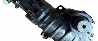
Amplifier KamAZ (Article 4310-3400020-03):
How to properly care for a gur
This applies not only to Kamaz, but to cars in general.
The guru won’t take much of your attention, but drivers only need to follow the basic norms and sets of rules that reduce the likelihood of a breakdown on the road, including reducing the likelihood of a breakdown due to the driver’s fault.
- Understanding how the guru works and being accountable for your actions is the most important thing.
- It is equally useful to know what kind of oil is used in the hydraulic booster.
- Also try to prevent the formation of leaks from the power steering system.
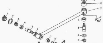
Power steering components
The design of the power steering includes parts and assemblies combined into one mechanism with a common closed loop.
Main components of the amplifier:
The purpose of the unit is to direct hydraulic oil, used as a working fluid, into the pipes and voids of the circuit.
The unit is designed to convert fluid pressure into mechanical work. This is done by means of a displacer and rods attached to them.
The material is used as a working fluid. This happens due to the properties of the liquid, such as fluidity and non-compressibility. The oil transmits the pump force to the hydraulic cylinder. In addition, it is used as a preservative and also lubricates rubbing parts, reducing friction.
Amplifier pump KamAZ-4310:
- Hydraulic power steering pump.
The purpose of the unit is to support the required pressure for the functioning of the mechanism, as well as to create fluid circulation in the circuit, which affects cooling. In addition, constant movement and pressure cleans the working fluid, driving it through the filter elements, and also seals parts and assemblies.
- Connectors (pipes, lines, voids).
Branch pipes, lines, voids create a solid mechanism united by one circuit.
Receives sensor signals, processes, analyzes, and reacts to the information received. Thus, the controller controls the amplifier.
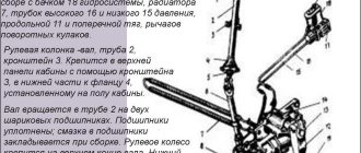
Power steering KamAZ 4310 device and adjustment
To understand how the amplifier functions, let's look at a schematic representation of the mechanism's operation. The figure shows that the movement of the KamAZ - 4310 vehicle in a straight position forces the auger (15) and the device that reorients the flow (20) to adhere to the middle. This position forms a single connection of elements: supply and discharge channels (26, 32, respectively), voids (7) and (25) of the hydraulic chamber. At the same time, the lubricant circulates freely, making its way from the pump through the control valve (19) and again enters the reservoir of the hydraulic circuit (31).
Turning the steering wheel (1), see diagram, provokes rotation of the screw (15). Removing the wheels (12) from the equilibrium position causes resistance from the rack piston (8), which controlled the linear movement. The resulting force tends to move the auger along the axis in the direction of rotation; this is prevented by the centering spring elements (23). The force exceeding the spring force moves the auger, moving the flow reorientation device behind it. The consequence of the actions taken is that the chamber void communicating with the discharge channel is disconnected from the drain channel and vice versa. The liquid pumped into the void of the channel by the pump acts on the rack valve (8), forming a pressure on the sectoral mechanism (6) of the bipod. It becomes easier to turn the wheels.
Performance indicators
Structurally, the mechanism that controls the movement of vehicles includes: a device that changes the movement of the shaft at an angle, a device that distributes the force of an axial type fluid, and an integrated force chamber. Regarding the transmission mechanism used, the following are used: “auger-ball”, “nut-displacer”, toothed quarter circle with a conical rack.
Amplifier parameters (3400020):
| Index | Explanation |
| Force on the front pair of wheels, (t) | 5,5 |
| Torsion impulse of the amplifier output shaft, pressure 9MPa, (Nm) | 4000 |
| Possible heating of the amplifier lubricant, (°C) | 90 |
| Ratio of driven and driven amplifier teeth | 21.7 to 1 |
| Bipod shaft seal GUR KamAZ 4310 size, (mm) | 57,2*76*8 |
| Booster pressure limiting valve (MPa) | 8-9 |
| Passability of the amplifier distribution device, (dm 3 /min) | 15 |
| Amplifier bipod eversion, (deg.) | 86 |
| Amplifier groove, directivity | left |
| Amplifier weight, (kg) | 47,2 |
KamAZ amplifier bipod oil seal:
Causes and symptoms of malfunctions
The hydraulic booster is reliable and breaks down extremely rarely. Often breakdowns are associated with violation of operating conditions, or due to use of the car in the cold. The latter is accompanied by the fact that the bipod oil seal of the power steering KamAZ 4310 is leaking. The reason for the failure of the oil seals is an increase in oil thickness, as a result, an increase in pressure in the circuit. The positive point is that if the amplifier breaks unexpectedly, this will not affect safety; the driver will feel an increase in the force on the steering wheel.
In addition, it is necessary to prevent clogging of the mechanism, since dust and dirt often get inside the unit. This phenomenon leads to malfunction; this occurs due to increased wear and friction inside the amplifier, since dust and dirt act as an abrasive.
COOLANT
Coolant is a balanced mixture of antifreeze and water. The presence of antifreeze allows you to expand the range of operating temperatures, lowering the freezing point and increasing the boiling point of the coolant. The additives included in antifreeze protect the engine cooling system from cavitation corrosion. Coolants based on ethylene glycol are approved for operation of KAMAZ engines. The list of coolants approved for use in the cooling system of KAMAZ engines is given in tables B.8, B.9. The use of coolants is mandatory in all climate zones. In a temperate climate zone, it is recommended to use coolants with an antifreeze concentration of 40% (OZh-40 “Lena”, “Tosol-A40M”, “Cool Stream Standard 40”, etc.). In cold climate zones, it is recommended to use coolants with an antifreeze concentration of 65% (OZh-65 “Lena”, “Tosol-A65M”, etc.). During operation, it is necessary to monitor the density of the coolant. Thus, the density of the coolant at a temperature of 20 °C should be:
- Coolant-40 “Lena” - (1.075 - 1.085) g/cm3;
- “Cool Stream Standard 40” - (1.068 - 1.070) g/cm3;
- “Tosol-A40M” - (1.078 - 1.085) g/cm3;
- Coolant-65 “Lena” and “Tosol-A65M” - (1.085-1.1) g/cm3;
- “Antifreeze (-45) FELIX®” - (1.065-1.085) g/cm3;
- Antifreeze “X-Freese Carbox” G12 - (1.065-1.085) g/cm3;
- Coolant -40 “TORSA-TOSOL-103” - (1.075-1.085) g/cm3;
- SINTEC Antifreeze-40 - (1.065-1.085) g/cm3;
- “KAMAZ-STANDARD 40” - (1.068 - 1.072) g/cm3;
- "KAMAZ-STANDARD 65" - (1.083 - 1.085) g/cm3.
If the density of the coolant is below the minimum permissible value, the fluid must be replaced. If the coolant density is higher than the maximum permissible value, the coolant density should be adjusted by adding demineralized water. Coolants ES Compleat and Old World Fleet Charge Coolant are recommended for refilling the cooling system of Cummins engines. Old World Fleet Charge finished products are available with varying antifreeze contents. Coolant Old World Fleet Charge Coolant 50/50 (antifreeze content - 50%) is operational down to minus 37 ° C; Old World Fleet Charge Coolant 60/40 (antifreeze content - 60%) is operational down to minus 52 °C. Finished ES Compleat products are available with different antifreeze contents. Coolant ES CompleatTM EG Premix 50/50 (antifreeze content – 50%) is operational down to minus 36 °C; ES CompleatTM EG Premix 60/40 (antifreeze content – 60%) is operational down to minus 54 °C.
Depending on the operating conditions, it is necessary to use one or another product. For complete information on the coolants recommended by the company, see the Cummins Engine Operation and Maintenance Manual.
Pumping the hydraulic booster KamAZ 4310
If there is a problem with the amplifier, measures should be taken to identify and correct it as quickly as possible. The operation of a problematic product will ultimately lead to a complete replacement of the unit. In order not to lose the amplifier, you need to take care of the device and adjusting the KamAZ 4310 power steering, along with pumping, are mandatory procedures.
You need to start working with the accompanying units of the amplifier, such as the pump. Remember that parts that fail are not restored in such units, since they are manufactured in compliance with strict tolerances and fits. The procedure is carried out on the car with the steering tags removed and the engine turned off.
First perform the manipulations:
- Reduce wheel imbalance, regulate the force of air impact on the tire;
- Check the lubrication level of the steering wheel and wheel hubs;
- Adjust the wheel bearings;
- Check the operation of the vibration dampers and the correct alignment of the drive wheels.
Detection of air bubbles in the amplifier is a reason to carry out the pumping procedure.
Checking the fluid level in the amplifier:
- Hang the car 4320 so that the wheels of the product do not touch the ground. To do this, use stands that are placed under the beams of the machine.
- Remove the filler cap from the amplifier expansion tank;
- Remove the trim from the amplifier exhaust valve and install a rubber tube on it instead. Place the free end of the tube into a container with lubricant;
- Open the amplifier bypass valve half a turn;
- Turn the steering wheel to the left until it stops, pour liquid into the expansion tank;
Pumping the KamAZ amplifier:
- Start the engine, then top up the lubrication amplifier into the conservator and check that the level corresponds to the mark. Monitor the air outlet, if there is no air, close the valve; Turn the steering wheel to the right, then in the opposite direction. Make sure that the steering wheel remains in place, open the power bypass valve 1/2. Check to see if air is flowing into the container; if not, tighten the valve;
- Bleed the power steering as many times as necessary to stop air escaping from the free end of the tube;
- If clear grease comes out of the free end, stop the engine. Remove the tubes, replace the caps and plugs, check the lubricant level in the amplifier expander, and top up if necessary.
(097) 056-05-93,, (093) 651-44-42
Shop
Repair
Hydraulic booster without fitting
If the hydraulic booster is not equipped with a fitting for bleeding air, the pumping process is performed slightly differently. Initially, operations are carried out with the engine turned off. To do this, the front of the car is hung out. Liquid is poured into the tank to the level. Then you need to turn the steering wheel from lock to lock several times.
Then the car lowers to the ground. Then you will need to start the engine and let it run for a few minutes. Next, the steering wheel must be turned again from the stop, first to the left, then to the right, without stopping in the extreme positions. In this case, you need to monitor the liquid level and top up if necessary.
During this operation, foam forms on the surface of the liquid in the tank. Then you need to stop the engine and wait until the foam disappears. The pumping has been completed.
If you constantly hear noise under the hood, this indicates wear on the bearings of the power steering pump. In this case, the pump is replaced.