The hydraulic steering control system is an integral part of any KAMAZ, since without it, steering the vehicle will be, if not impossible, then very difficult. Thanks to this unit, the driver can turn the steering wheel with greater ease. You can learn more about what the KAMAZ power steering system is and how to de-air it from this material.
Characteristics of power steering
First, let's look at the main characteristics of the power steering on a KAMAZ 6520 or any other model. Let's start with the purpose and device.
Purpose
The main purpose of the power steering system is to minimize the effort used to turn the steering wheel when steering, as well as performing many maneuvers when driving at low speeds. In addition, thanks to the power steering system, the impact on the steering wheel will be more noticeable if the car is moving at high speed. If the power steering fails for some reason, this will result in the driver having to exert significantly more effort to turn the steering wheel.
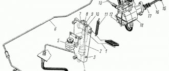
General diagram of the KAMAZ steering control operation
Device
Now let's briefly look at the power steering device.
This system consists of the following elements:
- Switchgear. This component is used to direct the flow of working fluids, in particular hydraulic oil, into the lines and cavities of the system.
- Hydraulic cylinder. This device performs the function of converting hydraulic pressure into mechanical work of pistons and rods.
- The working material in this case is hydraulic fluid. With its help, force is transferred from the pump to the hydraulic cylinder. In addition, thanks to the liquid, all rubbing components and components of the system are lubricated.
- KAMAZ power steering pump. Thanks to this device, the pressure required for normal operation is constantly maintained in the system. This element is also used to circulate the working fluid.
- Connecting elements or lines. They are used to bring together all the working components of the system.
- Control device or electronic unit. With its help, direction and adjustment of the operation of the amplifier are carried out.
Features of the pump
The pumping device is installed in the collapse of the BC. Domestic trucks use a gear top drive, but the device itself is of the blade type. In accordance with the technical documentation, this unit is characterized by double action, that is, with one turn of the steering wheel it carries out two cycles of suction and discharge.
Let's take a brief look at the operating principle. When the wheel turns, the rotor blades begin to rotate, which, in turn, are pressed against the stator device. Working fluid begins to flow into those blades that, when pressed, coincide with the holes on the body. Further, thanks to the same blades, the consumable material enters the narrower holes that exist between the stator and the rotor.
At the moment when the working surfaces can coincide with the holes on the distribution disk, the consumable material will come out beyond it. Next, the oil will pass through the lower valve; for this, high pressure is formed in the system.
The working fluid, leaving the cavity behind the distribution disk, will flow onto the rotor blades, as a result of which they will be pressed even more tightly against the stator plane. The process of pumping the substance, as well as its absorption, is carried out simultaneously in two places. As the number of revolutions of the rotor device increases, liquid from the surface behind the disk will not pass through the calibration hole. By generating pressure in the system, the bypass valve is opened, and part of the consumable material, through the manifold, is again supplied to the suction surface (the author of the video about replacing the hydraulic booster on a KAMAZ is Mathur Malay).
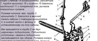
The steering column (Fig. 6.2) consists of shaft 1, pipe 4 and is attached to the top panel of the cabin using a bracket, in the lower part - to a pipe fixed to its floor.
The shaft is mounted in a pipe on two ball bearings. The upper bearing is locked by thrust and expansion rings, the lower by a lock washer and nut. The axial clearance in the bearings is also adjusted with a nut. The bearings are equipped with seals. Lubricant is added to the bearings during assembly.
The steering wheel is attached to the upper end of the shaft. The lower end of the shaft is equipped with a groove for attaching the cardan transmission fork.
The cardan transmission transmits forces from the steering column shaft to the drive gear of the angular gearbox and consists of a shaft (Fig. 6.3), a bushing and two cardan joints.
Each hinge consists of forks and a cross with four needle bearings installed in cups. The bearings are equipped with sealing rings; during assembly, 1-1.2 g of lubricant is placed in each of them. Before assembling the cardan transmission, 2.8...3.3 g of lubricant is also placed in the bushing and the splines of the rod and bushing are covered with it.
When assembling the cardan transmission, the splines of the shaft and bushing are connected so that the hinge forks are in the same plane. This ensures uniform rotation of the shafts.
The hinge fork connected to the bushing is installed on the steering column shaft; The shaft fork is connected to the shaft of the drive gear of the angular gearbox. The forks are fixed with wedge screws that go into the holes, locked with nuts and cotter pins.
Rice. 6.3. Cardan transmission: 1, 9 - forks; 2 — needle bearing; 3 - glass; 4 — cross; 6 - shaft; 7 - seal; 8 bushing; 10 mounting hole
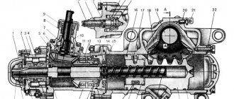
Rice. 6.4. Steering mechanism: a— steering mechanism assembly with bevel gear: 1—cover; 2 - reactive plunger; 3 — control valve body; 4 - spring; 5—adjusting spacer; 6 — bearing; 7— drive shaft with gear; 8— needle bearing; 9 — sealing device; 10 - body; 11 — driven gear; 12 — bearing; 13 — retaining ring; 14— cover; 15 - thrust ring; 16 - ring; 17 - screw; 18 - bypass valve; 19 — cap; 20 - cover; 21 - crankcase; 22 – piston-rack; 23 - plug; 24 - screw; 25 - nut; 26 - gutter; 27 - ball; 28 - sector; 29 - nut; 30 — lock pin; 31 - ring; 32 — body; 33 — thrust bearing; 34 - plunger; 35 - spring; 36 — spool; 37 — washer; 38 - nut; 39 — adjusting screw; 40 - nut; 41 - crumb; 42 - seal; 43 - ring; 44 — adjusting washer; 45 - thrust ring; 46 - bipod shaft b - angular gearbox: 1 - drive shaft with gear; 2 - sealing device; 3 — housing cover; 4 — drive gear housing; 5,7, 10 - ball bearings; 6 — adjusting gasket; 8, 15 — sealing rings; 9 — retaining ring; And - driven gear; 12 - thrust cover; 13 — gear housing; 14 - spacer sleeve
The wheel gearbox transmits the force from the cardan transmission to the steering screw. It is attached to its crankcase with studs. The gear ratio is 1:1.
The shaft (Fig. 6.4) with the drive gear is installed in the housing on ball and needle bearings. The ball bearing is fixed on the shaft with a nut, the thin edge of which is pressed into the groove of the shaft. The needle bearing is secured with a retaining ring. In the angular gearbox of the steering mechanism of the KamAZ-4310 vehicle, the drive shaft with gear is mounted on two ball bearings in the housing. The bearings are held on the shaft by a nut. In connection with these design changes, the shape of the housing and housing cover has been changed accordingly. The driven gear is installed in the gearbox housing on two ball bearings secured with a nut and a lock washer. Axial forces are absorbed by the cover and the thrust ring. The driven gear is connected to the screw by splines, which allows it to move relative to the gear. In this case, the hydraulic booster spool mounted on the shaft can move relative to the housing. The mesh of the gears is adjusted by changing the thickness of the shims.
The steering mechanism is assembled together with an angular gearbox, a control valve and a hydraulic booster cylinder. Bolted to the left spring bracket.
The steering gear housing (Fig. 6.4) contains: a screw with a nut, a power piston with a rack and a gear sector with a bipod shaft. The steering gear housing is also a hydraulic booster cylinder.
The nut is connected to the piston with set screws. The screws are cored after assembly.
To reduce friction forces in the steering mechanism, the screw rotates in the nut on balls located in the grooves of the screw and nut. Two round grooves are installed in the hole and groove of the nut, forming a tube. When the screw is turned in the nut, the balls, rolling along the helical groove, fall into a tube consisting of grooves, and again into the helical groove, i.e., continuous circulation of the balls is ensured.
The gear sector with the bipod shaft is installed on a bronze bushing in the steering gear housing and in the hole in the side cover attached to the crankcase. To adjust the gap in the engagement of the rack with the sector, their teeth have a variable thickness along the length.
Adjustment of the engagement and fixation of the gear sector with the bipod shaft in the axial direction is ensured by a screw screwed into the side cover. The head of the adjusting screw fits into the hole in the bipod shaft and rests against the thrust ring. The axial movement of the bipod shaft relative to the screw head should not exceed 0.02...0.08 mm. It is adjusted by selecting the thickness of the adjusting washer. After adjusting the gear gap, the screw is locked with a nut. A bypass valve is screwed into the crankcase, allowing air to escape from the hydraulic booster. The valve is closed with a rubber cap. The bipod is installed on the shaft splines and secured with bolts. A drain plug is screwed into the lower part of the crankcase (see Fig. 6.4)
The hydraulic booster consists of a spool-type control valve (switchgear), a hydraulic cylinder-crankcase, a pump with a reservoir, a radiator, pipelines and hoses.
The control valve housing (Fig. 6.4) is secured with studs to the bevel gear housing. The control valve spool is mounted on thrust bearings at the front end of the steering gear. The inner rings of large-diameter bearings are pressed with a nut against reaction plungers located in three holes in the housing together with centering springs. Thrust bearings with a spool are fixed on the screw with a collar and a nut. The conical washer is installed under the nut with the concave side facing the bearing. There are grooves in the valve body on both sides. Therefore, the thrust bearings and the spool with the screw can move in both directions from the middle position by 1.1 mm (the working stroke of the spool), while shifting the plungers and compressing the springs.
Bypass and safety valves and plungers with springs are also installed in the holes of the control valve body (Fig. 6.5). The safety valve connects the high and low oil pressure lines at a pressure of 6500...7000 kPa (65...70 kgf/cm2). The bypass valve connects the cylinder cavities when the pump is not running, reducing the resistance of the amplifier when turning the wheels.
The power steering cylinder is located in the steering gear housing. The cylinder piston is equipped with a seal ring and oil grooves.
The hydraulic booster pump is installed between the engine cylinder blocks. The pump shaft is driven by the high pressure fuel pump gear.
The pump is a vane type, double-acting, i.e., two cycles of suction and discharge occur during one revolution of the shaft. The pump (Fig. 6.6) consists of a cover, a housing, a rotor with a shaft, a stator and a distribution disc. The shaft, on the splines of which the rotor is mounted, rotates on 4 ball and needle bearings. The drive gear is locked on the shaft with a key and secured with a nut. Blades are installed in the radial grooves of the rotor.
The stator is installed in the housing on pins and pressed to the distribution disk with bolts.
A rotor with blades is installed inside a stator, the working surface of which has an oval shape. When the rotor rotates, its blades, under the influence of centrifugal forces and oil pressure in the central cavity of the rotor, are pressed against the working surfaces
Rice. 6.5. Hydraulic booster control valve: 1, 10 - plungers; 2, 4,7, 8 — springs; 3, 6, 12 — valves; 5 - cap; 9 — body; 11—spool; 13 - gasket
stator, distribution disk and housing, forming chambers of variable volume.
As their volume increases, a vacuum is created and oil from the tank enters the chambers. Subsequently, the blades, sliding along the surface of the stator, move along the grooves to the center of the rotor, the volume of the chambers decreases and the oil pressure in them increases. When the chambers coincide with the holes in the distribution disk, oil enters the pump discharge cavity. The working surfaces of the housing, rotor, stator and distribution disk are carefully ground, which reduces oil leakage.
A bypass valve with a spring is installed in the housing cover. Inside the bypass valve there is a safety ball valve with a spring, which limits the pressure in the pump to 7500...8000 kPa (75...80 kgf/cm2).
The pump safety valve is adjusted to an opening pressure 500 kPa (5 kgf/cm2) higher than the opening pressure of the safety valve (Fig. 6.5) located in the steering mechanism.
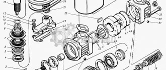
Rice. 6.6. Hydraulic booster pump: 1 - gear; 2 - shaft; 3 - key; 4 - bearing; 5 - ring; b - seal; 7— needle bearing; 8 - cover; 9—oil level indicator; 10 - bolt; 11 - gasket; 12— filter stand; 13 - safety valve; 14 — cover; 15 — gasket; 16 — tank; 17 - mesh filter; 18 - collector; 19 — tube; 20 - gasket; 21 - cover; 22 - safety valve; 23 - bypass valve; 24 — distribution disk; 25 — blade; 26 - stator; 27 — body; 28—rotor
In relation to the hydraulic system of the power steering of the KamAZ-4310 vehicle, the opening pressure of the safety valve in the control valve body is set to 7500... 8000 kPa (75...80 kgf/cm2), and the opening pressure of the safety valve in the pump is 8500...9000 kPa (85...90 kgf/cm2) cm2).
The bypass valve and the calibrated hole connecting the pump discharge cavity with the output line limit the amount of oil circulating in the booster as the pump rotor speed increases.
A manifold is attached to the pump body (see Fig. 6.6) through a gasket, creating excess pressure in the suction channel, which improves the operating conditions of the pump, reducing noise and wear of its parts.
Rice. 6.7. Steering drive: 1 - cover: 2 - gasket; 3, 16 — springs; 4, 6, 14, 15 — liners; 5, 13 - fingers; 7 - butter; 8 — rod end; 9, 12, 20 — sealing strips; 10 - transverse thrust; 11 — longitudinal thrust; 17 — gasket; 18 — threaded cover; 19— washer
The tank with the filler cap and filter is screwed to the pump body. The tank cover is bolted to the filter stand. The joints of the cover with the bolt and the body are sealed with gaskets. A safety valve is installed in the lid, limiting the pressure inside the tank. The oil circulating in the hydraulic system of the amplifier is cleaned in a strainer. There is an oil level indicator in the filler plug.
The radiator is designed to cool the oil circulating in the hydraulic booster. The radiator, in the form of a double-bent finned tube made of aluminum alloy, is mounted in front of the radiator of the engine lubrication system with strips and screws.
The hydraulic booster units are connected to each other by high and low pressure hoses and pipelines. High pressure hoses have a double internal braid; the ends of the hoses are sealed into ferrules.
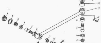
The steering drive consists of a bipod, longitudinal and transverse steering rods and levers.
The steering knuckle levers are pivotally connected to the transverse rod, forming a steering trapezoid that ensures the steering wheels rotate to the appropriate angles. The levers are inserted into the conical holes of the knuckles and secured with keys and nuts.
The tips, which are the heads of the hinges, are screwed onto the threaded ends of the transverse rod (Fig. 6.7). By rotating the tips, the toe-in of the front wheels is adjusted, compensating for possible divergence during operation due to wear of parts, which increases tire wear and makes driving more difficult. The rod ends are fixed with bolts. The rod joint consists of a pin with a spherical head, liners pressed by a spring to the head, fastening parts and a seal. The spring ensures a backlash-free connection and compensates for wear on the surfaces of the parts.
The longitudinal rod is forged together with the hinge heads. The hinges are closed with threaded caps and sealing strips. The hinges are lubricated through oil nipples. The steering axles of the wheels are installed with lateral inclinations in the transverse plane inward by 8°. Therefore, when the wheels turn, the front of the car rises slightly, which creates stabilization of the steered wheels (the tendency of the steered wheels to return to the middle position after a turn).
The tilt of the kingpins in the longitudinal plane back by 3° creates stabilization of the steered wheels due to the centrifugal forces that arise when turning.
When the steering wheel is released after a turn, the normal load on the steered wheels and centrifugal forces create stabilizing moments that automatically return the steered wheels to the center position. This makes driving a car much easier. The axes of rotation of the wheels are inclined with their outer ends down by 1°, forming a wheel camber, which makes it difficult for the wheels to reverse camber in operation due to wear of the bearings. Driving with reverse camber increases tire wear and makes driving harder.
In the steering drive of the KamAZ-4310 vehicle, the transverse steering rod has a U-shape due to the presence of the main gear housing of the front drive axle.
Steering operation. When moving in a straight line, the spool (Fig. 6.8) of the control valve is held by springs in the middle position. The oil supplied by the pump passes through the annular slots of the control valve, fills the cylinder cavities and is drained through the radiator into the tank. As the rotor speed increases, the intensity of circulation and oil heating in the hydraulic booster increases. The bypass valve restricts oil circulation. As oil flow increases, a pressure difference is created across the end surfaces of the valve due to an increase in the resistance of the calibrated hole. When the force from the pressure difference on the valve exceeds the force of the spring, it will move and connect the discharge cavity of the pump to the tank. In this case, most of the oil will circulate along the pump-tank-pump circuit.
When the steering wheel is turned, the force through the cardan transmission, the angular gearbox, is transmitted to the steering gear screw.
If significant effort is required to turn the wheels, the screw, screwing into the nut (or unscrewing from it), will displace the thrust bearing and spool, moving the plunger and compressing the centering springs. The displacement of the spool in the body changes the cross-section of the annular slots associated with the cavities of the cylinder. Reducing the cross-section of the drain gap with a simultaneous increase in the amount of oil due to an increase in the cross-section of the injection gap leads to an increase in pressure in one of the cavities of the cylinder. In the other cavity of the cylinder, where the change in cross-sections of the slots is opposite, the oil pressure does not increase. If the difference in oil pressure on the piston creates a force greater than the resistance force, then it begins to move. The movement of the piston through the rack causes rotation of the sector and then, through the steering drive, rotation of the steered wheels.
Continuous rotation of the steering wheel maintains the displacement of the spool in the housing, the difference in oil pressure in the cylinder cavities, the movement of the piston and the rotation of the steering wheels.
Stopping the steering wheel will stop the piston and the steering wheels at the moment when the piston, continuing to move under the influence of the oil pressure difference, moves the screw with the spool in the axial direction to the middle position. Changing the cross-section of the slots in the control valve will lead to a decrease in pressure in the working cavity of the cylinder, the piston and driven wheels will stop. This ensures the “following” action of the amplifier according to the angle of rotation of the steering wheel.
The pump discharge line supplies oil between the plungers. The greater the resistance to turning the wheels, the higher the oil pressure in the line and at the ends of the plungers, and, consequently, the resistance to their movement when the spool moves. This creates a “following” action based on the resistance to turning the wheels, i.e., the “feeling” of the road.
At the maximum oil pressure value of 7500...8000 kPa (75...80 kgf/cm2), the valves open, protecting the booster hydraulic system from damage.
To quickly exit a turn, release the steering wheel. By the combined action of reaction plungers and springs, the spool moves and is held in the middle position. The steered wheels, under the influence of stabilizing moments, turn to the middle position, displace the piston and push the liquid into the drain line. As the center position is approached, the stabilizing moments decrease and the wheels stop.
Spontaneous rotation of the wheels under the influence of impacts on uneven roads is possible only when the piston moves, i.e., pushing a portion of oil from the cylinder into the tank. Thus, the amplifier acts as a shock absorber, reducing shock loads and reducing spontaneous steering wheel turns.
In the event of a sudden stop of the engine, pump or loss of oil, it is possible to control the driver's efforts. The driver, turning the steering wheel, moves the plungers with the spool until they stop in the control valve body, and then rotation is ensured only due to the mechanical connection of the steering parts. The force on the steering wheel increases. To reduce the resistance force when the piston moves, a bypass valve located in the plunger ensures oil flows from the cylinder cavities.
Inspection and identification of defects
Carefully inspect the contents and remember (you can take a photo) what was placed where and how (more attention should be paid to the position of the cylinder). You can twist the power steering pulley and carefully use tweezers to check how the blades move in the grooves of the shaft
All parts should be pulled out without effort, since they do not have any fixations, but the central axis is firmly fixed and cannot be removed.
We inspect the shaft from the reverse side, parts (power steering housing and cover wall) touching them, for burrs or grooves, everything is perfect for me.
Now we remove the entire internal economy onto “clean” rags and begin to study it.
We carefully examine the shaft; all its grooves have very sharp edges on all sides. One of the end sides of each groove has a pronounced sharpness inward, which, when moving the blade inside the groove with a constant slope towards this side, will greatly complicate its movement (this may be the first component of poor power steering performance). The side parts of the shaft grooves are also “sharpened”; this can be felt if you run your finger in different directions along the end (outer circumference), as well as along the side parts of the shaft in different directions. Otherwise the shaft is perfect, has no flaws or nicks.
KamAZ power steering device
An amplifier is a set of parts and mechanisms combined into a closed system. The element bases are:
Directs streams of liquid (lubricant) into the nozzles, channels and cavities of the power steering.
Volumetric hydraulic motor of reciprocating motion of a cylindrical shape.
The product converts the pressure generated by oil into the mechanical action of pistons and rods.
The working fluid, which is oil, is poured into the KamAZ power steering. The lubricant transmits force to the hydraulic cylinder from the pump. The material also prevents wear of surfaces, acting as a lubricant and sealant.
Hydraulic power steering pump KamAZ-65115, etc.
The mechanism serves as a guarantor that maintains the level of constant pressure necessary for the normal functioning of the system. In addition, the pump constantly moves lubricant through the cavities and lines of the device.
Parts help connect and close parts, mechanisms, assemblies into one device.
The mechanism controls the operation of the system, analyzes and distributes efforts across work areas.
KamAZ power steering diagram:
Device
The KamAZ power steering includes the following components:
- Distribution mechanism. It is used to direct flows of working media, including hydraulic oil, into the components and compartments of the power steering system.
- Hydraulic cylinder. Used as a converter of hydraulic pressure into mechanical impulses necessary for the movement of pistons and rods.
- Hydraulic fluid. This is the working medium that transmits force from the pumping unit to the hydraulic cylinder. The liquid lubricates the contacting elements and components.
- KamAZ power steering pump. Maintains the pressure required for correct operation of the system. The KamAZ power steering pump also circulates the working fluid.
- Elements for connecting nodes or highways. Necessary for combining all parts of the system into a single mechanism.
- Filter mechanism.
- Control device or electronic module. Used to guide and adjust work.
The KamAZ power steering device may differ slightly for different models of the Kama Automobile Plant.
How to change oil in power steering Kamaz
To change the power steering oil, you need to bleed it; this action will remove air from the system. Air should not be left in the system.
- First, you need to open the valve on the steering mechanism, it is also called the bypass valve;
- Then compress the centering springs. This can be done by turning the steering wheel to the left all the way;
- Fill the pump with oil;
- The power device must be turned on, and at this time you add oil slowly and gradually, and see if air bubbles come out of the hose. If the bubbles stop coming, that means enough;
- Screw back the bypass valve;
- Again, compress the centering springs, only now you need to turn the steering wheel to the right as far as possible, and the springs should compress, and immediately return it back to the left all the way, again twist the bypass valve to see if any air bubbles are released. After all the air has come out, the valve can be screwed back on;
- Do the action from the previous point until all the air comes out and only oil comes out of the valve.
How to remove an air lock from the power steering system
Suspend the front axle so that the wheels do not touch the ground. The truck is lifted with a jack and trestles are placed under the beam on both sides; Remove the caps from the neck of the tank through which the oil is poured; Remove the rubber pads from the bypass valve and fix them on the spherical head of the elastic hose. Place the other end in a glass vessel with a volume of 0.5 liters, half filled with oil; Unscrew the bypass valve half to three-quarters of a turn; Turn the steering wheel to the left all the way; Fill the pump tank with lubricant to a level where it will not drop; Start the engine and add oil while rotating the crankshaft at low speed. It is necessary that the oil level does not decrease until the formation of air bubbles stops at the outlet of the hose located on the bypass valve; Next, you need to close the bypass valve; Turn the steering wheel to the right all the way and back, to the left all the way. Hold the steering wheel in this position and turn the bypass valve half to three-quarters of a turn. Here you also need to control the release of air bubbles. After the air has escaped, the bypass valve closes; Repeat step 9 several times
It is important to ensure that clean oil (without air impurities) ultimately comes out of the valve; Stop the motor; Remove the hose and attach the protective cap to the valve head. Then check the lubricant level in the pump reservoir
If the tie rod was disconnected, you need to reinstall it.
Adjusting power steering KAMAZ
The steering mechanism can only be checked and adjusted in the position when the engine is turned off and the longitudinal steering rod is disconnected.
Before starting work, you need to check the wheel balancing, pressure level, presence of oil in the steering and hubs, settings of wheel bearings and rods, functioning of shock absorbers, quality of installation of the front wheels, oil level in the pump.
To check the force of the steering column, a dynamometer mounted on the wheel rim is used. The force is checked at different positions of the steering wheel: when turning 2 or more turns from the initial position, when turning three-quarters of a turn, when the wheel passes the initial position.
Forces that do not correspond to the specified values in the required positions must be adjusted. This may require dismantling the unit, its partial or complete disassembly:
Not available:
| № | Part code | Name | Part Information |
| 5320-3402015-02 | Steering wheel assembly | Quantity per 6520 1 Model 5320 Group Steering control Subgroup Steering wheel Part serial number 015 | Not available |
| 53205-3403008 | bracket | Quantity per 6520 1 Model 53205 Group Steering control Subgroup Steering control (column) mounting Part serial number 008 | Not available |
| 53205-3444006 | Steering column with propeller shaft | Quantity per 6520 1 Model 53205 Group Steering control Subgroup Steering column Part number 006 | Not available |
| 53205-3444054 | Adjustment handwheel | Quantity per 6520 1 Model 53205 Group Steering control Subgroup Steering column Part number 054 | Not available |
| 53205-3444069 | Front column cover | Quantity per 6520 1 Model 53205 Group Steering control Subgroup Steering column Part number 069 | Not available |
| 5320-3402064 | Lower steering wheel cover | Quantity per 6520 1 Model 5320 Group Steering control Subgroup Steering wheel Part serial number 064 | Not available |
| 53205-3444024 | Bracket | Quantity per 6520 1 Model 53205 Group Steering control Subgroup Steering column Part number 024 | Not available |
| 53205-3444070-30 | Rear column cover | Quantity per 6520 1 Model 53205 Group Steering control Subgroup Steering column Serial part number 070 Additionally Not interchangeable with a part previously released under the same number | Not available |
| 53205-3444074 | Protective casing | Quantity per 6520 2 Model 53205 Group Steering control Subgroup Steering column Part number 074 | Not available |
| 53205-3444078 | Shroud bracket | Quantity per 6520 1 Model 53205 Group Steering control Subgroup Steering column Part number 078 | Not available |
| 53205-3444083 | M6 bolt for fastening the switch | Quantity per 6520 2 Model 53205 Group Steering control Subgroup Steering column Part number 083 | Not available |
| 53205-3444066 | Ring sealing | Quantity per 6520 1 Model 53205 Group Steering control Subgroup Steering column Part number 066 | Not available |
| 1/25741/11 | Nut M5-6N | Quantity per 6520 4 Fastening part yes Material steel 50 (steel with tensile strength 490-784 (50-80) MPa (kg/mm2) Coating galvanized | Not available |
| 864413 | Clamp 45 | Quantity per 6520 1 Coated uncoated | Not available |
| 1/59707/21 | Bolt M10x1.25-6gx25 | Quantity per 6520 2 Fastening part yes Material steel 80 (steel with tensile strength 784-980 (80-100) MPa (kg/mm2) Coating galvanized | Not available |
| 1/13069/21 | Bolt M10x1.25-6gx30 | Quantity per 6520 2 Fastening part yes Material steel 80 (steel with tensile strength 784-980 (80-100) MPa (kg/mm2) Coating galvanized | Not available |
| 1/32796/01 | Phillips head screw | Quantity per 6520 1 Fastening part yes Material steel 40 (steel with tensile strength 333-490 (34-50) MPa (kg/mm2) Coating galvanized | Not available |
| 1/03892/01 | Screw M5-6gx8 | Quantity per 6520 3 Fastening part yes Material steel 40 (steel with tensile strength 333-490 (34-50) MPa (kg/mm2) Coating galvanized | Not available |
| 1/76711/01 | Self-tapping screw 4.9x12.7 | Quantity per 6520 5 Fastening part yes Material steel 40 (steel with tensile strength 333-490 (34-50) MPa (kg/mm2) Coating galvanized | Not available |
| 1/61023/11 | Nut M8-6N low | Quantity per 6520 1 Fastening part yes Material steel 50 (steel with tensile strength 490-784 (50-80) MPa (kg/mm2) Coating galvanized | Not available |
| 1/09776/21 | Bolt M5-6gх12 | Quantity per 6520 4 Fastening part yes Material steel 80 (steel with tensile strength 784-980 (80-100) MPa (kg/mm2) Coating galvanized | Not available |
| 1/05193/01 | Flat washer 5.45x10x1 | Quantity per 6520 1 Fastening part yes Material steel 40 (steel with tensile strength 333-490 (34-50) MPa (kg/mm2) Coating galvanized | Not available |
| 2126-3404010-20 | Instrument and starter switch with anti-theft device | Quantity per 6520 1 Model 2126 Group Steering control Subgroup 3404 Serial part number 010 Additionally Not interchangeable with a part previously released under the same number | Not available |
| 4573731151 | Windshield wiper switch with washer 40.3709 | Quantity per 6520 1 Group Winch Subgroup 4573 Serial part number 731 Additionally Not interchangeable with a part previously released under the same number | Not available |
| 4573431142 | Switch for direction indicators, low and high beam 66.3709 | Quantity per 6520 1 Group Winch Subgroup 4573 Serial part number 431 Additionally Not interchangeable with a part previously released under the same number | Not available |
Power steering repair
Repair of KamAZ power steering should be carried out by specialists with the necessary skills. It is best to order the service at specialized car services that service KamAZ vehicles or trucks.
Common faults
In general, repair of the hydraulic power steering on KamAZ trucks is required very often, since it is a fairly reliable system. Especially if the rules for using the node are followed and its scheduled maintenance is performed.
Typically, interruptions in power steering operation occur at sub-zero air temperatures, in winter, and during temperature changes. All failures of the KamAZ power steering can be divided into two categories: mechanical and hydraulic (both types of failures can occur in any part of the unit).
The main problem is related to the pump on KamAZ power steering: the viscosity of lubricants increases, which contributes to the squeezing out of oil seals and oil leakage. This malfunction especially often appears on cars that are operated incorrectly, for example, left in a parking lot with the wheels turned out. When starting the engine, the pressure increases only on one side, and the oil seal is squeezed out.
At positive temperatures, interruptions in the operation of the mechanism occur due to dirt and dust that are blown into the system. This leads to depressurization of individual elements, which increases wear on bushings and rods. Rust forms on the latter quite quickly, which also contributes to the rapid wear of the bushings. When using a truck, after 200-300 km, play appears between these parts, which causes a knocking sound from the steering rack. Gear adjustment is also often required.
How to remove an air lock from the system
When refilling with lubricants or after repairs, it is necessary to remove air from the system (bleed the power steering on a KamAZ).
The sequence of actions is as follows:
- Hanging the front axle so that the wheels do not touch the ground. The truck is lifted with a jack and trestles are placed under the beam on both sides.
It is better if this work is carried out by specialists who know how to bleed the power steering on a KamAZ correctly so that there is absolutely no air left in the system.
Replacing parts when repairing power steering
When starting repairs of the hydraulic booster, power steering pump housing and other elements of the system, you need to understand that parts that have exhausted their service life cannot be restored, they can only be replaced with new ones. The production of spare parts with high precision and smooth surfaces is possible only in factories that specialize in the creation of such parts. That is why it is necessary to buy components for KamAZ from reliable companies that supply from official manufacturers.
Adjusting the steering gear
The steering mechanism can only be checked and adjusted in the position when the engine is turned off and the longitudinal steering rod is disconnected.
Before starting work, you need to check the wheel balancing, pressure level, presence of oil in the steering and hubs, settings of wheel bearings and rods, functioning of shock absorbers, quality of installation of the front wheels, oil level in the pump.
To check the force of the steering column, a dynamometer mounted on the wheel rim is used. The force is checked at different positions of the steering wheel: when turning 2 or more turns from the initial position, when turning three-quarters of a turn, when the wheel passes the initial position.
Forces that do not correspond to the specified values in the required positions must be adjusted. This may require dismantling the unit, its partial or complete disassembly:
- First, the adjustment is made in the third position, the adjustment is carried out using the bipod shaft screw;
- Then the first position is adjusted - you need to tighten or loosen the mounting location of the thrust bearings (partial disassembly of the mechanism is required);
- Adjustment in the second position is carried out with complete disassembly of the hydraulic booster.
Source
Steering of the KamAZ-5320 vehicle and the MTZ-80 tractor with hydraulic booster
ContentIntroduction
1. Purpose and general characteristics of the steering control of the KamAZ - 5320 vehicle and the MTZ - 80 wheeled tractor with hydraulic booster
2. Design and operation of the steering control of the KamAZ - 5320 vehicle and the MTZ - 80 wheeled tractor
3.Basic steering adjustments
4. Possible steering malfunctions and their elimination
5.Steering maintenance
Conclusion
Bibliography
Applications
Introduction
The production of steel and rubber, gasoline and oils, syntax materials, machine tools and tools, rolling bearings and automotive glass, the construction of service stations and roads - all this taken together determined the possibility of creating a modern automobile industry.
One of the most important features in the development of our automobile industry is the further expansion of the production of trucks.
However, the improvement of domestic industry does not only follow the path of quantitative growth. In its development, a progressive technical policy is being implemented, which provides, in particular, for the mass production of diesel trucks with a carrying capacity of 5 - 8 tons, which will make it possible to develop freight transportation by road trains with heavy lifting capacity and to economically solve complex national economic transport problems.
Already in February 1976, the first vehicles of the KamAZ family rolled off the main assembly line of the Kama Automobile Plant and their mass production began, and on December 26, 1976, the State Commission accepted the first stage of the Kama plant complex into operation. On February 16, 1981, KamAZ commissioned a second assembly line and began production of the base model of the family of off-road vehicles. This automotive giant is capable of providing a sharp increase in the production of cars and heavy-duty road trains. It is designed to produce 150,000 cars and 250,000 diesel engines per year.
KamAZ vehicles are modern heavy-duty vehicles with limited axle load. KamAZ vehicles are equipped with a high-speed diesel model 740, which meets modern technical and economic requirements developed by the Yaroslavl Motor Plant.
The design of these vehicles implements a number of new solutions for systems, mechanisms and assemblies. However, the achieved high operational and technical properties of cars are associated not only with the use of new design solutions, but also with some general complication of the design of cars, which places higher demands on the organization of their operation. This determines the restructuring of the KamAZ vehicle maintenance system, the development of a network of branded service and centralized repair of the most complex vehicle components at factories.
Trucks of KamAZ production associations, as their production develops, will play an increasingly important role in the national economy of our country.
In addition to considering the KamAZ vehicle, this work will also consider the MTZ-80 tractor.
Tractor MTZ - 80
MTZ-80 tractors are equipped with tires of increased standard sizes. Despite significant changes in the design of the tractor, most assembly units and parts are interchangeable. Tractor unification has reached 70%. The number of attachments has been increased to 300. The MTZ-80 tractor was the first Soviet tractor to successfully pass tests at the international tractor testing center in Nebraska (USA). Confirmation of the high technical level and quality of Belarus tractors is the assignment of the State Quality Mark to all major tractor models and the awarding of eight gold medals at various international exhibitions and fairs. Based on the MTZ-80 tractor, modifications are produced: cotton-growing tractor - MTZ-80X (since 1976).
The MTZ-80 tractor is a wheeled, universal row-crop tractor, traction class 1.4. The MTZ-80 tractor is designed for agricultural and transport work using various mounted and trailed units. The mounted hydraulic system of the MTZ-80 tractor is universal, separate and modular, with power and positional control of the tillage depth, with mechanical fixation of the hitch in the transport position.
The tractor is equipped with a four-stroke liquid-cooled diesel engine D-240 (D-243) with direct fuel injection, starting from an electric starter. The D-240L engine installed on the MTZ-80L tractor is started from a starting engine with a blocking device that prevents the engine from starting when the gear is engaged. The tractor is equipped with power and position control of the hydraulic linkage system, automatic differential locking of the rear axle, and a two-speed PTO. additional gearbox, creeper and pneumatic drives for trailer brakes.
The clutch is friction, single-disc, dry, permanently closed.
The gearbox is mechanical with nine forward gears and two reverse gears. The gearbox reduction gearbox, which consists of two pairs of cylindrical spur gears, doubles the number of gears.
The final drive consists of a pair of bevel gears with spiral teeth.
The power (position) regulator is installed on the bracket of the rear hydraulic cylinder and is connected by oil lines to the distributor and the hydraulic adhesion weight increaser (GSV). The presence of such a regulator in the hydraulic system in combination with the GSV helps to increase the productivity of the tractor unit and reduce fuel consumption per hectare.
The track of the rear and front wheels is adjustable. This allows tractors to be widely used in the cultivation of both low-stem and high-stem crops with different row spacings.
The MTZ-80 tractor has a safe, sealed, noise-vibration-insulated, spacious cabin, with ventilation and heating systems, and a comfortable seat, adjustable for the height and weight of the tractor driver.
The MTZ-80 "Belarus" tractor is equipped with a separate-unit mounted hydraulic system, power steering, independent and synchronous rear PTO drives, instrumentation (tachospeedometer with hour meter, ammeter, oil pressure indicators in the engine lubrication system, water temperature, air pressure in the trailer brake pneumatic system), towing device, remote cylinders, breakaway couplings, hoses for connecting the tractor hydraulic system to the hydraulic system of the machines.
1. Purpose and general characteristics of the steering control
of the KamAZ - 5320 vehicle and the MTZ - 80 wheeled tractor with hydraulic booster.
The steering control is used to change and maintain the selected direction of movement of the vehicle. The main way to change the direction of movement is to turn the front guide wheels in a horizontal plane relative to the rear wheels. The steering must ensure correct turning kinematics and traffic safety, small forces on the steering wheel, and prevent the transmission of shock from road unevenness to the steering wheel. The steering mechanism increases the driver's effort on the steering wheel and improves the accuracy of vehicle control. Thanks to this, it remains possible to drive the car when the amplifier is not working, for example, when the engine suddenly stops, which increases traffic safety.
The hydraulic booster makes driving easier and increases safety. Hydraulic booster, using engine energy to turn and hold the wheels, reduces driver fatigue, improves the vehicle's maneuverability and ensures control in difficult conditions, such as sudden tire damage. When driving on uneven roads and terrain, the hydraulic booster reduces shock loads in the steering, reducing the likelihood of damage, and increases the comfort and safety of driving.
The steering drive transmits the forces of the driver and the hydraulic booster to the steered wheels, ensuring their rotation at mutually different angles. This reduces slipping and, consequently, tire wear and makes it easier to control the car.
The KamAZ-5320 vehicle uses mechanical steering with a hydraulic booster. The steering mechanism with an angular gear reducer is equipped with a steering gear with working pairs of the type screw - nut with circulating balls and rack - gear sector. The steering gear ratio is 20:1.
The hydraulic booster is designed according to a scheme with constant fluid circulation, which helps reduce the pump load. The maximum fluid pressure in the system is 7500 - 8000 kPa. The hydraulic booster cylinder is built into the steering gear housing. The spool-type control valve is equipped with centering springs and reaction plungers, creating on the steering wheel a feeling of resistance to turning the wheels. The hydraulic booster pump is a rotary vane type, double-acting, driven by the engine fuel pump gear. The hydraulic booster radiator, which provides cooling of the circulating fluid, is installed on the radiator of the cooling system.
The steering drive is mechanical, with articulated joints. The steered wheels are installed with an inclination - camber in the transverse. The steered wheels are inclined in the transverse direction by 8 degrees, in the longitudinal plane by 3 degrees to create stabilization of wheel control. The maximum turning angles of the wheels are 45 degrees, providing a minimum turning radius of the car along the outer wheel of 8.5 m with a width of the occupied corridor of 4.5 m.
2. Design and operation of the steering control of the KamAZ - 5320 vehicle and the MTZ - 80 wheeled tractor
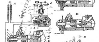
The steering consists of (adj. 1.) steering wheel 1, steering column 2 (add. 1.), cardan transmission 6, angular gearbox 9, steering gear 10, hydraulic booster (including control valve 8, radiator 7, pump 14 with tank 15) and steering gear.
Steering Column
(add. 2.) consists of shaft 1, pipe 4 and is attached to the top panel of the cabin using a bracket, in the lower part - to a pipe fixed to its floor,
Shaft 1 is installed in the pipe on two ball bearings 3. The upper bearing is locked with thrust and clamping rings, the lower one with a lock washer 7 and a nut 8. The axial clearance in the bearings is also adjusted with a nut 8. The bearings are equipped with seals.
The steering wheel is attached to the upper end of shaft 1. The lower end of the shaft is equipped with a groove for attaching the cardan transmission fork.
Lubricant is added to the bearings during assembly.
Cardan transmission
transmits forces from the steering column shaft to the drive gear of the angular gearbox and consists of shaft 6, bushing 8 and two cardan joints (Appendix 3.).
Each hinge consists of forks and a cross 4 with four needle bearings 2 installed in the machines 3. The bearings are equipped with sealed rings; during assembly, 1-1.2 grams of lubricant are placed in each of them and the splines of the rod and bushing are covered with it.
When assembling the cardan transmission, the splines of the shaft 6 and bushing 8 are connected so that the forks of the hinges 5, 9 are in the same plane. This ensures uniform shaft rotation.
The hinge fork 9, connected to the bushing 8, is installed on the steering column shaft; fork 5 of shaft 6 are connected to the shaft of the drive gear of the angular gearbox. The forks are fixed with wedge screws entering hole 10, locked with nuts and cotter pins.
Angular reducer
transmits force from the cardan drive to the steering screw. It is attached to its crankcase with studs. The gear ratio is 1:1.
Shaft 7 (Appendix 4) with drive gear is installed in housing 10 on ball 6 and needle bearings 8. The ball bearing is fixed on the shaft with a nut, the thin edge of which is pressed into the groove of the shaft. The needle bearing is secured with a retaining ring. The driven gear is installed in the gearbox housing 32 on two ball bearings, secured by a nut 29 with a lock washer 30. Axial forces are perceived by the cover 14 and thrust ring 15. The driven gear is connected to the screw with 24 splines, which allows it to move relative to the gear. In this case, the hydraulic booster spool mounted on the shaft can move relative to the housing 3. The engagement of the gears is regulated by changing the thickness of the gaskets 5.
Steering gear
assembled together with an angular gearbox, a control valve and a hydraulic booster cylinder. Bolted to the left spring bracket.
The steering gear housing 21 (Appendix 5) contains: a screw 24 with nuts 25, a power piston 22 with a gear rack, and a gear sector 28 with a bipod shaft 46. The steering gear housing is also a hydraulic booster cylinder.
Nut 25 is connected to the piston by set screws 17. The screws are cored after assembly.
To reduce the friction forces in the steering mechanism, the screw 24 rotates in the nut 25 on balls 27 placed in the grooves of the screw and nut. Two grooves 26 of circular cross-section are installed in the hole and groove of the nut, forming a tube. When the screw is turned in the nut, the balls, rolling along the screw groove, fall into a tube consisting of grooves, and again into the screw groove, i.e. ensures continuous circulation of the balls.
The gear sector 28 with the bipod shaft 46 is installed on a bronze bushing in the steering gear housing 21 and in the hole of the side cover 41, attached to the crater. To adjust the gap in the engagement of the rack with the sector, their teeth have a variable thickness along the length.
Adjustment of the engagement and fixation of the gear sector with the bipod shaft in the axial direction is ensured by a screw 39 screwed into the side cover 41.
The head of the adjusting screw 39 enters the hole of the bipod shaft relative to the screw head should not exceed 0.02-0.08 mm. It is adjusted by selecting the thickness of the adjusting washer 44. After adjusting the gear gap, screw 39 is locked with nut 40. A bypass valve 18 is screwed into the crankcase, allowing air to be released from the hydraulic booster. The valve is closed with a rubber cap 19. The bipod 12 is installed on the splines of the shaft 46 and secured with bolts 12 (Appendix 1). A drain plug 23 (Appendix 5) is screwed into the lower part of the crankcase.
Hydraulic booster
consists of a spool-type control clan (switchgear), a hydraulic cylinder-crankcase, a pump with a reservoir, a radiator, pipelines and hoses.
The control valve housing 3 (Appendix 5) is secured with studs to the bevel gear housing 32. The control valve spool 36 is installed at the front end of the steering gear screw 24 on thrust bearings 33. The inner rings of large-diameter bearings are pressed with a nut to the reaction plungers 2, located in three holes in the housing 3 together with centering springs 4, 35. The thrust bearings are fixed to the screw by a spool collar and nut 38. Conical washer 37 is installed under the nut with the concave side facing the bearing. There are grooves in the valve body on both sides. Therefore, thrust bearings 33, spool 36 with screw 24 can move in both directions from the north position by 1.1 mm (spool stroke), while shifting plungers 2 and compressing springs 4.
In the holes of the housing 9 of the control valve (Appendix 6), bypass 6 and safety valves 3, 12 and plungers 10 with springs are also installed. The safety valve connects the high and low oil pressure lines at a pressure of 6500-7000 kPa. The bypass valve connects the cylinder cavities when the pump is not running, reducing the resistance of the amplifier when turning the wheels.
The power steering cylinder is located in the steering gear housing. The cylinder piston is equipped with an O-ring and oil grooves.
Hydraulic booster pump
installed between the engine cylinder blocks. The pump shaft is driven by the high pressure fuel pump gear.
Vane type pump, double acting, i.e. For one revolution of the shaft, two cycles of suction and heating occur. The pump (Appendix 7) consists of a cover 21, a housing 27, a rotor 28 with a shaft 2, a stator 26 and a distribution disk 24. Shaft 2, on the splines of which the rotor is mounted, rotates on ball 4 and needle 7 bearings. Gear 1 of the drive is locked on the shaft with a key 3 and secured with a nut. Blades 25 are installed in the radial grooves of the rotor 28.
Stator 26 is installed in the housing on pins and pressed to the distribution disk with bolts.
The rotor 28 with blades 25 is installed inside the stator 26, the working surface of which has an oval shape. When the rotor rotates, its blades under the action of centrifugal forces and oil pressure in the central cavity of the rotor are pressed against the working surfaces of the stator, distribution disk and housing, forming chambers of variable volume.
As their volume increases, a vacuum is created, and oil from the tank enters the chambers. Subsequently, the blades slide along the surfaces of the stator, shift along the grooves to the center of the rotor, the volume of the chambers decreases, and the oil pressure in them increases.
When the chambers coincide with the holes in the distribution disk, oil enters the pump discharge cavity. The working surfaces of the housing, stator rotor and distribution disk are carefully ground, which reduces oil leakage.
A bypass valve 23 with a spring is installed in the housing cover. Inside the bypass valve there is a safety ball valve 22 with a spring, which limits the pressure in the pump to 7500-8000 kPa.
The bypass valve and calibrated hole connecting the pump discharge cavity with the output line limit the amount of oil circulating in the booster as the pump rotor speed increases.
A manifold 18 is attached to the pump housing 27 through a gasket, ensuring the creation of excess pressure in the suction channel, which improves the operating conditions of the pump, reducing noise and wear of its parts.
Tank 16 with filler cap 14 and filter 17 is screwed to the pump housing. The tank cover is secured with a bolt 10 to the filter stand 12.
The joints of the cover with the bolt and the body are sealed with gaskets. A safety valve 13 is installed in the lid, limiting the pressure inside the tank. The oils circulating in the hydraulic system of the amplifier are cleaned in strainer 17. An oil indicator 9 is mounted in the filler plug.
Radiator
designed to cool the oil circulating in the hydraulic booster.
Radiator 7 (Appendix 8), in the form of a double-bent finned tube made of aluminum alloy, is attached in front of the radiator of the engine lubrication system with slats and shrouds.
The hydraulic booster units are connected to each other by high and low pressure hoses and pipelines. High pressure hoses have a double internal braid; the ends of the hoses are sealed into ferrules.
Steering drive
consists of a bipod, longitudinal and transverse steering rods and levers.
The steering knuckle arms, pivotally connected to the transverse rod, form a steering trapezoid, which ensures that the steered wheels rotate at mutually different angles. The levers are inserted into the conical holes of the knuckles and secured with keys and nuts.
Tips 8, which are the heads of the hinges, are screwed onto the threaded ends of the transverse rod 10 (Appendix 9). By rotating the tips, the toe-in of the front wheels is regulated, compensating for possible discrepancies in operation due to wear of parts, which increases tire wear and makes driving harder. The rod ends are secured with bolts. The rod joint consists of a pin 5 with a spherical head, liners 4, 6 pressed by a spring 3 to the head, fastening parts and a seal. The spring ensures a backlash-free connection and compensates for wear on the surfaces of the parts.
The longitudinal rod 11 is forged together with the hinge heads. The hinges are closed with threaded caps 18 and sealing strips 12. The hinges are lubricated through oil nipples. Rotary axles - wheel pins are installed with lateral inclinations of the transverse plane inward by 8 degrees. Therefore, when the wheels turn, the front of the car rises slightly, which creates stabilization of the steered wheels (the tendency of the steered wheels to return to the middle position after a turn).
The tilt of the longitudinal plane pins back by 3 degrees creates stabilization of the steered wheels due to the centrifugal forces that arise when turning.
When the steering wheel is released after a turn, the force of weight and centrifugal forces create stabilizing moments that automatically return the steering wheels to the center position. The axes of rotation of the wheels are inclined with their outer ends down by 1 degree, forming a wheel camber, which makes it difficult for the wheels to reverse camber in operation due to wear of the bearings. Driving with reverse camber increases tire wear and makes driving harder.
Steering operation
. When moving in a straight line, spool 11 (adj. 10) of the control valve is held in the middle position by springs. The oil supplied by pump 19 passes through the annular slots of the control valve, fills the cavities of cylinder 5 and is drained through radiator 26 into tank 23. With increasing rotor speed, the intensity of circulation and heating of the oil in the hydraulic booster increases. Bypass valve 22 limits oil circulation. As the oil flow rate increases, a pressure difference is created on the end surfaces of valve 22 as a result of an increase in the calibrated hole 20. When the force from the pressure difference on the valve exceeds the spring force, it will move and connect the discharge cavity of the pump to the tank. In this case, most of the oil will circulate along the pump-tank-pump circuit.
When turning the steering wheel 1, the force through the cardan gear 3, angular gearbox 4, is transferred to the steering gear screw 6.
If significant force is required to turn the wheel, then screw 6 is screwed into nut 7 (or unscrewed from not) displacing the thrust bearing 14 and spool 11, while shifting plunger 15 and compressing the centering springs 16. Displacement of spool 11 in housing 12 changes the cross-section annular slots connected to the cavities of the cylinder. Reducing the cross-section of the drain slots with a simultaneous increase in the amount of oil due to an increase in the cross-section of the injection slot leads to an increase in pressure in one cavity of the cylinder. In the other cavity of the cylinder, where the change in cross-sections of the slots is opposite, the oil pressure does not increase. If the difference in oil pressure on piston 9 creates a large resistance force, then it begins to move. The movement of the piston through the rack causes rotation of sector 8 and then, through the steering drive, rotation of the steered wheels.
Continuous rotation of the steering wheel is supported by the mixing of the spool in housing 12, the difference in oil pressure in the cylinder cavities, the movement of the piston and the rotation of the steered wheels.
Stopping the steering wheel will stop the piston and the steering wheels at the moment when the piston, continuing to move under the influence of the oil pressure difference, moves screw 6 with spool 11 in the axial direction to the middle position. Changing the cross-section of the slots in the control valve will lead to a decrease in pressure in the working cavity of the cylinder, the piston and driven wheels will stop. This ensures the “following” action of the amplifier according to the angle of rotation of the steering wheel.
The discharge line of the pump 18 supplies oil between the plungers 15. The greater the resistance force to the rotation of the wheels, the higher the oil pressure in the line and at the ends of the plungers, and, consequently, the resistance force to their movement when the spool is displaced. This creates a “following” action based on the resistance to turning the wheels, i.e. "feeling of the road"
At the maximum oil pressure value of 7500 - 8000 kPa, valves 13 and 21 open, protecting the hydraulic system of the amplifier from damage.
To quickly exit a turn, the steering wheel is released. By the combined action of reaction plungers and springs, the spool moves and is held in the middle position. The steered wheels, under the influence of stabilizing moments, turn to the middle position, displace the piston and push the liquid into the drain line. As the center position is approached, the stabilizing moments decrease and the wheels stop.
Spontaneous rotation of wheels under the influence of impacts on uneven roads is possible only when the piston moves, i.e. pushing a portion of oil from the cylinder into the tank. Thus, the amplifier acts as a shock absorber, reducing shock loads and reducing spontaneous steering wheel turns.
In cases of sudden stoppage of the engine, pump or loss of oil, the driver can still control the effort. The driver, turning the steering wheel, displaces the plungers 15 by the spool 11 until they stop in the control valve body 12, and then the rotation is ensured only due to the mechanical connection of the steering parts. The force on the steering wheel when moving the piston 9, the bypass valve 10, located in the plunger, ensures the flow of oil from the cavities of the cylinder.
The next thing I want to add to my work is:
Purpose and general characteristics of the steering system of
the MTZ-80 tractor with hydraulic booster.
It serves to transmit force from the driver to the steering drive and turn the steering wheel. There are several types of steering mechanism: worm-roller, worm-sector and screw-nut. A worm-roller steering mechanism is used on tractors with mechanical steering without hydraulic booster, while other types are used with hydraulic booster. The hydraulic booster serves to reduce the driver's effort on the steering wheel when turning the tractor.
Power steering pump repair
I'll tell you how I repaired the power steering pump. But first, a little background.
The steering wheel works without any complaints in a cold car in summer and winter. But as soon as the car warms up, especially in the summer, the steering wheel at idle becomes very tight, as if there is no power steering. In winter, this problem does not manifest itself as much, but it is still present. If you apply gas, the steering wheel immediately turns easier (though not quite ideally, but still easier). At the same time, the pump does not knock, does not ring, does not leak, etc... (the snotty rack is not taken into account) the oil is fresh and ideal (especially since, thanks to the condition of the rack, it is updated regularly!), the cardan is lubricated and does not stick!
In general, this is a clear sign of lack of performance of the power steering pump when the oil is hot at idle. I didn’t suffer for long, but in the end I decided to deal with this problem, spent a lot of time, scoured the Internet, understood the principle of the pump’s operation, found a similar description and decided to rebuild my “old” pump.
How to pump power steering
How to fill oil and bleed power steering
The procedure for replacing fluid and pumping power steering is carried out in strict accordance with the existing algorithm. Some automakers may add their own features to it. If you have a manual for your car, we recommend that you read the relevant section. In general terms, the steps must be performed in the following sequence:
- Raise the vehicle completely on a lift or with the front wheels off the ground.
- If necessary, drain the old fluid from the expansion tank. To do this, remove the return hose (going to the power steering system) from the expansion tank and put a plug on it so that liquid does not spill out of the hose. A hose leading to an empty bottle is connected to the released tap on the tank, where the old hydraulic fluid is supposed to be drained.
- It is most convenient to pump out the main volume of liquid with a syringe and pour it into a separate bottle. When there is very little liquid left, move on to the next point.
- Fill the expansion tank with working fluid to the top.
- Next, you should turn the steering wheel from side to side (from lock to lock) several times so that the old fluid remaining in the system flows out through the hose. Since the new fluid displaces the old, do not forget to monitor the oil level in the tank so that air does not get into the hose.
- If the fluid level drops, add it again.
- Start the engine for 2-3 seconds and turn it off. This is done so that the liquid begins to spread throughout the system.
It is important to remember that if you have aired the power steering system, the air can be expelled by bleeding it by rotating the steering wheel from side to side. However, do not start the engine under any circumstances, since the air in the system is critical for the power steering pump and can cause its failure
Pumping out oil with a syringe
- Next, add working fluid to the tank to the MAX level and repeat the procedure by starting the engine. Repeat this cycle 3-5 times.
- The signal to stop pumping is the fact that air from the return hose stops entering the drain bottle. This means that there is no more air left in the hydraulic system and fresh, clean fluid enters the reservoir.
- After this, you need to reinstall the return hose (connect it to the expansion tank where it was originally installed).
- Refill the reservoir to the MAX level, then start the engine.
- To pump the hydraulic booster, you need to slowly turn the steering wheel 4-5 times from the left to the right stop. At the stop points, pause for 2-3 seconds. If there is any air left, it should escape into the expansion tank. During the inspection process, we make sure that the pump does not make any extraneous noise.
- An indicator that pumping has ended will be the absence of air bubbles on the surface of the liquid in the tank.
- After this, close the expansion tank tightly.
Bleeding the power steering system
The system can also be pumped without starting the engine, “cold”. To do this, just rotate the steering wheel from left to right stops. At the same time, old fluid and air leave the system. However, most automakers still recommend bleeding the system with the engine running.
The fluid level in the reservoir should be between the MIN and MAX marks. Remember that when heated, the liquid expands, so you should not pour it beyond the existing mark.
How to remove an air lock from the system?
The need to bleed the system usually arises after refueling it or eliminating breakdowns in the operation of the unit. Air entering the lines leads to less efficient operation of the hydraulic booster, so the only solution in this case is to remove the air.
So, how to bleed the power steering:
- First you need to move the front axle so that the car's wheels do not touch the ground. Using a jack, you should place supports under the beam on both sides. If the wheels are on the ground, bleeding of the system cannot be started.
- Then you need to remove the filler cap of the expansion tank located under the hood.
- Next, the rubberized cap should be removed from the bypass valve, and an elastic pipe should be installed on its head. In this case, its open part should be lowered into a glass container, the volume of which will be at least half a liter. The vessel itself should be filled halfway with the working fluid.
- Then the bypass valve should be opened slightly, half a turn.
- After completing these steps, turn the steering wheel to the left all the way. After this, the working fluid is poured into the expansion tank until its level decreases.
- Then you need to start the power unit, and while it is operating at minimum speed, pour a little liquid into the expansion tank, but without allowing the level to drop. Do this until bubbles stop coming out of the pipe that is installed on the bypass valve. After this, the valve itself can be closed.
- Next, the steering wheel should be turned all the way to the right, and then to the left. And holding the steering wheel in this position, again unscrew the bypass valve halfway and observe whether bubbles come out of the pipe. When they stop coming out, the valve can be tightened.
- This operation must be carried out several times, ultimately a clear liquid will come out of the valve, in which any impurities or air bubbles should be absent. If bubbles continue to come out, the procedure should be repeated several more times, but do not forget to monitor the volume of working material in the expansion tank.
- Then all you have to do is turn off the motor and remove the pipe from the valve head. Put the cap on the head itself, and then again diagnose the volume of liquid in the tank. If there is a need, it will need to be added. Further assembly of all components is carried out in reverse order.
KamAZ power steering malfunctions
The advantage of the product is that KamAZ power steering malfunctions appear due to violations of operation and maintenance. Mechanism repair is a rare occurrence, but if breakdowns do occur, they occur at sub-zero temperatures.
Since the amplifier involves mechanics that interact between devices via hydraulics, faults are divided into:
- Mechanical type;
- Hydraulic type.
Replacing the KamAZ power steering oil seal:
Temperature changes negatively affect the hydraulics of the mechanism. Minus values make the working fluid thick, which increases the load on the oil seals and joint seals of the KamAZ-65222 vehicle, etc. The impact of increased pressure leads to oil leaks.
Violation of operating rules negatively affects the components and mechanisms of the amplifier. To extend the service life of the hydraulic booster, you need to take a competent approach to operation. So, leaving the car in the parking lot, the wheels of the vehicle are set to a level position. Otherwise, uneven load on the oil seal will lead to damage.
During the warm season, dirt and dust pose a danger. The penetration of abrasive particles into the mechanism of KamAZ-65117 and other models leads to increased friction and wear of the surfaces of parts. The impact entails depressurization of the system, wear of bushings, rods and other components.
Moisture seeps into the resulting gaps, causing rust on unprotected parts and causing increased wear. Operating the amplifier with similar problems leads to knocking in the steering rack, after which only replacing the KamAZ power steering will help. In order not to go to extremes, you need to tune the amplifier on time. The procedures performed are adjustment and pumping of the device.
Common power steering faults
It must be said right away that repairing KAMAZ power steering is a procedure that our compatriots do not encounter so often. If the driver follows the basic rules for operating the unit, and also carries out its maintenance in a timely manner, then the likelihood that it will fail will be minimized. As practice shows, problems with the performance of the hydraulic booster mainly arise in the cold season. In general, all malfunctions can be divided into mechanical and hydraulic failures, both of which can occur in any part of the device.
As you know, any hydraulic system most often exhibits malfunctions in frosty conditions, in particular, temperature changes. After all, you need to remember that the pumping device pumps high pressure, so if the viscosity of the liquid in the system increases, this will lead to the squeezing out of the seals and, accordingly, its leakage. The problem of oil seals is especially evident in cars whose drivers do not follow operating rules, for example, leaving the car in a parking lot with the wheels twisted. This will lead to the fact that after starting the engine, the pressure will increase only on one side, accordingly, the oil seal will squeeze out in any case.
As for the warm season, in summer malfunctions usually appear as a result of dirt and dust getting into the system. If any part is depressurized, the wear of the bushings, as well as the rods, will be faster. The rods usually rust quite quickly, resulting in accelerated wear of the bushings. When operating a car with such a problem, after several hundred kilometers, there will be a large gap between these elements, and this, in turn, will lead to the steering rack starting to make a knock (author of a video about repairing the system in a garage - channel EIGHT ATMOSPHERE).
Serious fault
Now you know why oil foams in the power steering, and that its appearance can be very dangerous. If you were unable to fix the problem yourself, it is better to contact a service center. This will be much cheaper than replacing all system components of the circuit. At the same time, it is better to deliver the car to the service station using a tow truck, because we are talking about the integrity of your car, your health and even life.
Power steering is one of the main systems of the mechanism that sets the direction of movement. Its purpose is to facilitate vehicle control and ensure a stable position on the road.
Leakage of working fluid
Very often, power steering malfunctions come down to leakage of working fluid. It can leak in places where pipelines are attached or in case of damage to these pipelines.
In the first case, it is recommended to replace the clamps on the pipelines. If the pipeline is damaged, it must be replaced, which will require draining the working fluid from the system. Moreover, it is advisable to change all pipelines at once. After replacing the pipelines, new fluid is poured into the system and pumping is carried out.
It is important to remember that reusing power steering fluid is not recommended, as this can lead to failure of power steering components. If there is a video in the article and it does not play, select any word with the mouse, press Ctrl+Enter, enter any word in the window that appears and click “SEND”
Thank you
If there is a video in the article and it does not play, select any word with the mouse, press Ctrl+Enter, enter any word in the window that appears and click “SEND”. Thank you.
When filling the KamAZ power steering system with oil or after troubleshooting, it is necessary to remove air from it (“bleed” the steering).
To do this you need:
- Raise the front axle so that the wheels do not touch the ground. Using a jack, place trestles under the beam on both sides. But under no circumstances start pumping with the wheels standing on the ground. Or disconnect the longitudinal link from the steering bipod.
- Remove the pump reservoir filler cap.
- Remove the rubber cap from the steering gear bypass valve and place a transparent elastic hose on the spherical head of the valve, the open end of which is lowered into a glass container with a capacity of at least 0.5 liters. The vessel should be filled with oil to half its volume.
- Unscrew the steering gear bypass valve ½……3/4 turn.
- Turn the steering wheel LEFT until it stops.
- Pour oil into the pump reservoir until the level stops decreasing.
- Start the engine and, while operating at minimum crankshaft speed, add oil to the pump reservoir, not allowing the level to drop until air bubbles stop emitting from the hose placed on the bypass valve.
- Close the bypass valve.
- Turn the steering wheel to the RIGHT until it stops and back to the LEFT position. Keeping the steering wheel in the left position, unscrew the bypass valve ½……3/4 turn and again watch for the release of air bubbles. After the bubbles stop, close the bypass valve.
- Repeat the previous operation at least two times. As a result, clean (without air) oil should come out of the bypass valve. If the release of air bubbles continues, repeat the operation 1-2 more times, while monitoring the oil level in the pump reservoir, maintaining it between the marks on the level indicator.
- Stop the engine.
- Remove the hose from the spherical head of the bypass valve and place the protective cap on it. Check the oil level in the pump reservoir again and, if necessary, add oil. Install the pump reservoir filler cap. If you disconnected the longitudinal steering rod, install it in place.
The process of removing air from the system is complete.
It’s hard to imagine how the truck would handle if it weren’t for the KamAZ power steering system. The operation of the parts and mechanisms of this device has become familiar to a heavy unit. The unit helps the user apply minimal force to turn the steering wheel. In addition, a number of complex functions are performed that affect the safety of the machine.
Each mechanism is subject to wear and tear, which will lead to loss of performance. Hydraulic power steering is no exception; the condition of the unit affects other components of the engine. That is why timely maintenance is important to maintain the performance of the amplifier.
The weak link in the steering is the hydraulics. The entry of air bubbles into the channels of the mechanism can stall the work and create an emergency situation. In order to respond to an emergency situation in a timely manner, an experienced user knows how to upgrade the power steering on a KamAZ and restore functionality.
TRUCKS GAZ, ZIL, KAMAZ, URAL, MAZ, KRAZ
_________________________________________________________________________________________
Steering parts Kamaz-5320
The Kamaz-5320 steering (Fig. 1) is equipped with a hydraulic booster 7, combined in one unit with a steering mechanism, a hydraulic booster control valve 5 and an angular gearbox 6.
Fig.1. Steering Kamaz-5320 1 - steering wheel; 2 - column; 3 — cardan shaft; 4 - radiator; 5 — power steering control valve; 6 — angular gearbox; 7 - hydraulic booster with steering mechanism; 8 — longitudinal thrust; 9 — bipod; 10 - low pressure pipeline; 11 - high pressure pipeline; 12 — power steering pump; 13 — hydraulic system reservoir The Kamaz-5320 steering includes, in addition to the mentioned components, also: – steering column 2 with steering wheel 1; – propeller shaft 3 steering; – power steering pump 12 assembled with hydraulic system reservoir 13; – radiator 4; – high 11 and low 10 pressure pipelines; – steering rods. Mounting the steering bipod on modernized Kamaz vehicles Hydraulic power steering (power steering) Kamaz reduces the force that must be applied to the steering wheel to turn the front wheels, softens shocks transmitted from road unevenness, and also increases traffic safety, allowing you to maintain control over the direction of movement of the vehicle. in case of a front tire rupture. Kamaz-5320 steering column The Kamaz steering column (Fig. 2) is attached at the top to a bracket mounted on the interior panel of the cab, and at the bottom to a flange on the cab floor. Fig.2. Steering column KamAZ-5320 1 — column shaft; 2 — retaining ring; 3 — expansion ring; 4 — ball bearing; 5 - column pipe; 6 — holder with seal; 7 — lock washer; 8 - bearing adjustment nut The Kamaz steering column is connected to the steering mechanism by a cardan shaft. Shaft 1 of the column rotates in two ball bearings 4. The axial clearance in the bearings is adjusted with a nut 8. The lubricant in the bearings of the Kamaz steering column is replaced only when disassembling the column. Kamaz steering shaft cardan-5320 Kamaz steering shaft cardan (steering column cardan) (Fig. 3) with two hinges on needle bearings 4, into which grease 158 is added during assembly. In operation, the bearings do not need to be replenished with lubricant. To prevent dirt and moisture from entering the hinge joint, rubber rings 5 are used . Fig.3. Kamaz-5320 steering shaft cardan (steering column cardan) 1 - fork; 2, 9 — thrust rings; 3 — cross; 4 — needle bearing; 5.8 - sealing rings; 6 — fork with a splined rod; 7-ring sealing ring; 10 - fork with spline bushing The sliding spline connection of the Kamaz steering shaft cardan provides the ability to change the distance between the hinges when the cab is tipped over and serves to compensate for inaccuracies in the installation of the cab with the steering column relative to the frame with the steering mechanism, as well as their mutual movements. Before assembling the Kamaz steering shaft driveshaft (steering column driveshaft), 28...32 g of lubricant 158 is placed in the bushing, the splines are covered with a thin layer. To retain lubricant and protect the connection from contamination, a rubber seal with a thrust ring 9 is used, pressed by a holder 7. The Kamaz steering shaft cardan forks are attached to the column shaft and the drive gear shaft of the angular gearbox with wedges, which are tightened with nuts and cotter pins. Angular steering gearbox KamAZ-5320 Angular steering gearbox Kamaz (Fig. 4) with two bevel gears with a spiral tooth transmits rotation from the propeller shaft to the steering gear screw. Fig.4. Angular steering gearbox KamAZ-5320 1 - drive gear shaft; 2 - cuff; 3 — housing cover; 4 — drive gear housing; 5, 7, 10 – ball bearings; 6 — adjusting gaskets; 8, 15, 19 — sealing rings; 9 - retaining ring; 11 — driven gear; 12 – thrust cover; 13 — gear housing; 14 — spacer sleeve; 16 — bearing fastening nut; 17 — washer; 18 - thrust ring; 20 – protective cover The drive gear of the Kamaz angular gearbox is made integral with shaft 1 and is installed in housing 4 on ball bearings 5. The ball bearings are pressed onto the gear shaft and are held from axial movement by nut 16. To prevent spontaneous loosening, the nut collar is pressed into a groove on the gear shaft. The driven gear 11 rotates in two ball bearings 7, 10, mounted on the gear shank with interference. The driven gear of the Kamaz steering gearbox is held against longitudinal displacements by a retaining ring 9 and a thrust cover 12. The engagement of the bevel gears is controlled by spacers 6 installed between the housings of the drive gear and the bevel gear. Steering mechanism (steering mechanism) KamAZ-5320 Steering mechanism (steering mechanism) KamAZ with built-in hydraulic booster (Fig. 5) is attached to the front bracket of the front left spring. Fig.5. Steering mechanism (steering mechanism) KamAZ-5320 with built-in hydraulic booster 1 - front cover; 2 - power steering control valve; 3, 29 — retaining rings; 4 — floating bushing; 5, 7 — sealing rings; 6, 8 — spacer rings; 9 — set screw; 10 — bipod shaft; 11 — bypass valve; 12 — protective cap; 13 — rear cover; 14 — steering gear housing; 15 — piston-rack; 16 — magnetic drain plug; 17 - screw; 18 — ball nut; 19 - gutter; 20 - ball; 21 — angular gearbox; 22 — thrust bearing; 23 — spring washer; 24 - nut; 25 — thrust washer; 26 — adjusting washer; 27 — adjusting screw; 28 — lock nut of the adjusting screw; 30 — side cover The bracket is fixed to the car frame. Carter 14 of the Kamaz steering mechanism, in which the piston-rack moves, also serves as the working cylinder of the hydraulic booster. Screw 17 of the Kamaz steering mechanism has a ground helical groove. The same groove is ground in nut 18 and two holes are drilled into it. The holes are connected by an oblique groove milled on the outer surface of the nut. Two identical grooves 19 of semicircular cross-section, installed in the mentioned holes, and a groove form a bypass channel through which the balls 20, rolling out of the screw channel formed by the threads of the screw and nut, again enter it. To prevent the balls from falling out of the screw channel of the Kamaz steering mechanism, a tongue is provided in each groove that fits into the screw groove of the screw and changes the direction of movement of the balls. The number of circulating balls in a closed screw channel is thirty-one, eight of which are in the bypass channel. The helical groove on the screw in its middle zone is designed so that a slight interference is formed between the screw, nut and balls. This is necessary to ensure gap-free mating of parts in this area. When moving the nut, due to the fact that the depth of the groove on the screw from the middle to the ends increases slightly, a small gap appears in the mating of the screw and the nut. The specified gap is necessary to ensure greater durability of the middle part of the screw of the Kamaz steering mechanism, as well as to facilitate the return of the steered wheels to the middle position after turning and better stabilize the movement of the vehicle. In addition, loosening the seat of the ball nut on the screw towards the edges of its screw groove will make it easier to select the balls and assemble the ball screw pair. Since the transfer of axial force from the screw to the nut is carried out by means of balls, friction losses in the screw pair are minimal. After assembling the nut with the screw and balls, it is installed in the piston-rack 15 and fixed with two setscrews 9, which are cored into the annular groove made on the piston-rack. The piston-rack engages with the toothed sector of the bipod shaft 10. The Kamaz steering gear bipod shaft rotates in a bronze bushing pressed into the steering gear housing and into the aluminum side cover 30. The thickness of the teeth of the bipod shaft sector and the piston-rack is variable along the length, which allows you to change the engagement gap by moving the adjusting screw 27 screwed into the side cover . The head of the adjusting screw of the Kamaz steering mechanism, on which the thrust washer 25 rests, fits into the socket of the bipod shaft. The axial movement of the adjusting screw in the bipod shaft, maintained during assembly at 0.02 ... 0.08 mm, is ensured by selecting an adjusting washer 26 of the appropriate thickness. Parts of the Kamaz steering mechanism 27, 26, 25 are held in the bipod shaft socket by a retaining ring 29. The middle cavity between the rack teeth, which engages with the middle tooth of the gear sector of the bipod shaft, is made slightly smaller than the rest. This is necessary in order to avoid jamming of the worn steering mechanism after its adjustment when turning the bipod shaft. On the part of the screw of the Kamaz steering mechanism, located in the cavity of the angular gearbox housing, splines are cut with which the screw mates with the driven gear of the angular transmission. The Kamaz power steering control valve (Fig. 6) is attached to the bevel gear housing using a bolt and four studs (or five studs - one long and four short). Fig.6. Kamaz-5320 power steering control valve 1 - blind hole plunger; 2.5 - springs; 3 - threaded plug; 4 - check valve; 6 - spool; 7 — reactive plunger; 8 — valve body; 9 — sealing ring; 10 - safety valve Housing 8 of the Kamaz steering valve has a central hole made with great precision and six (three through and three blind) smaller holes located around it. The spool 6 of the Kamaz steering valve, located in the central hole, and the thrust bearings 22 (see Fig. 5) are secured to the screw with a nut 24, the collar of which is pressed into the groove of the screw 17. A conical spring washer 23 is placed under the nut, making it possible to regulate the tightening force of the thrust bearings. The concave side of the washer is directed towards the bearing. The large bearing rings face the spool. The Kamaz steering gear screw and the spool rigidly connected to them can move in each direction from the middle position by 1...1.2 mm. The amount of movement is determined by the depth of the recesses at the ends of the valve body and is limited by large bearing rings that abut the ends of the mentioned recesses. Two reaction plungers 7 (see Fig. 6) with centering springs between them are inserted into each of the three through holes of the valve body of the Kamaz steering mechanism. To ensure the same reactive force on the steering wheel of a Kamaz vehicle from oil pressure and the necessary equal active areas of the plungers when turning both right and left, plunger 1 is installed in each of the three blind holes facing the bevel gear. Total area of these three reactive elements is equal in size to the cross-sectional area of the screw at the point of its seal in the thrust cover of the angular gearbox of the Kamaz steering. One of the plungers, located in the blind holes, has a ball check valve 4 built in, which connects the high and low pressure lines in the event of a failure of the steering hydraulic system and thus ensures the ability to drive the car. In this case, the steering of the KamAZ-5320 works like a conventional mechanical system without reinforcement. A safety valve 10 is also installed in the Kamaz steering valve body, connecting the injection and drain lines at a pressure in the system exceeding 7357.5 ... 7848 kPa (75 ... 80 kgf/cm2), and thus protecting the pump from overheating, and the parts mechanism from excessive loads. The safety valve is located in a separate boss, which makes it possible to check, adjust or replace its parts if necessary. The cavities located under the front cover 1 (see Fig. 5) and in the angular gearbox of the KamAZ steering are connected by holes in the control valve body with the drain line and sealed at the ends with rubber O-rings. Similar rings seal all the fixed connections of the steering mechanism and power steering parts. The shaft of the Kamaz steering bipod is sealed with a cuff with a special thrust ring that prevents the working edge of the cuff from turning out under high pressure. The outer cuff protects the bipod shaft from dust and dirt. The piston in the cylinder and the Kamaz steering gear screw in the bevel gear housing cover are sealed with fluoroplastic rings 5 and 7 in combination with rubber spacer rings 6, 8. The adjusting screw for the Kamaz steering bipod shaft is sealed with a rubber ring. The shaft seal of the drive gear of the angular gearbox is combined and consists of two cuffs, which are fixed with a split thrust ring. In the Kamaz steering gear housing there is a drain plug 16 with a magnet, which serves to catch steel and cast iron particles, and a bypass valve 11, which is used when filling and bleeding the steering hydraulic system. High and low pressure hoses and pipelines are connected from the pump to the Kamaz control valve body. The former directs the oil to the mechanism, and the latter returns it to the hydraulic system reservoir. Steering gear KamAZ-5320 Steering gear KamAZ includes longitudinal and transverse steering rods.
Fig.7. Longitudinal steering rod KamAZ-5320 1 - ball pin; 2 — lining clip; 3 — protective cover; 4 — upper liner; 5 — lower liner; 6 — pressure spring; 7 — cover washer; 8 - cover; 9 — oiler; 10 — protective cover Kamaz longitudinal steering rod (Fig. 1) connects the bipod 9 of the steering mechanism with the upper arm of the left steering knuckle and is a solid forged part with non-adjustable hinges, including ball pin 1 (Fig. 7), upper 4 and lower 5 liners, a spring and a threaded cover 8 with a lock washer 7. The transverse rod of the Kamaz steering linkage (Fig. 8), included in the technological assembly unit “front axle assembly”, is tubular with threaded ends onto which ends 2 with ball joints are screwed. Fig.8. Cross steering rod KamAZ-5320 1 - transverse rod; 2 - tip; 3 — tip fastening bolt; 4 — sealing gasket; 5 - oiler; 6 - cover; 7- spring; 8 — cover fastening bolt; 9 — protective cover; 10 — lining clip; 11 — ball pin; 12 — upper liner; 13 — lower liner By changing the position of the tips on the Kamaz steering rod, you can adjust the toe-in of the steered wheels. Each tip is fixed with two bolts 3. The Kamaz tie rod joints are also non-adjustable, consisting of a ball pin 11, upper 12 and lower 13 liners, a spring 7 and a cover 6 attached with a sealing paronite gasket 4 to the rod end with bolts 8. Lubrication of the steering rod joints Kamaz is produced through oil nipples 5. Rubber pads are used to protect the hinges from dust and dirt getting into them. Replace the Kamaz-5320 tie rod in the following order: — hang up the front axle of the car; — unscrew and unscrew the nut securing the ball pin of the left rod end with the corresponding lower steering knuckle arm; — having knocked out the ball pin from the conical hole of the lever, disconnect the left tip of the steering linkage rod; — do the same operations with the right tie rod end and remove the tie rod from the car; — install the ends of the ball pins of the new transverse link ends in the holes of the lower arms, tighten and cotter the fastening nuts. The tightening torque of the tie rod ball pin nuts is 245…314 Nm (25…32 kg/cm). Install the transverse link so that the ball pin grease fittings on the link ends face rearwards in the direction of the vehicle; - lower the front axle. To replace the longitudinal steering rod of KamAZ-5320: — hang up the front axle of the vehicle and turn the steered wheels to the left until they stop; — unscrew and unscrew the nut securing the ball pin of the longitudinal steering rod on the side of the steering bipod; — having knocked the ball pin out of the conical hole of the bipod, disconnect the rod; — perform the same operations with the other hinge joint of the longitudinal link at the point where it connects with the upper arm of the left steering knuckle and remove the link from the car. Install the new Kamaz steering rod in the reverse order of removal, paying attention to the correct connection and the correspondence of the different rod heads to the installation locations. Lower the front axle of the vehicle. Tighten the Kamaz steering rod ball pin nuts with a torque of 245... 314 Nm (25... 32 kg/cm).
Checking and adjusting the steering of the KamAZ-5320, 55111, 4310 vehicle The technical condition of the steering of the KamAZ-5320, 55111, 4310 is generally assessed by the amount of free play of the steering wheel. To check it, it is necessary to install a equipped Kamaz-5320, 55111, 4310 vehicle on a horizontal platform with the steered wheels in the position for straight-line movement. The tire pressure of the front wheels should be 730 kPa (7.3 kgf/cm2); The hydraulic steering system must be filled and bled. The free play of the steering wheel at engine operating modes in the range of 600–1200 rpm should not exceed 25° (for new cars 15°). If the specified values increase, it is necessary to check the fastenings of the steering wheel, column, and cardan transmission of the KamAZ-5320, 55111, 4310 steering mechanism; the condition of the hinges, the attachment of the bipod, the adjustment and fastening of the steered wheels. If the steering wheel is axially displaced, nut 5 should be tightened (see Fig. 6.1) with a tightening torque of 30–80 Nm (3–8 kg/cm). The torque of the shaft rotation when the cardan drive is disconnected should be in the range of 60–80 Nm (6–8 kg/cm). Excessive tightening of the nut and then loosening it is unacceptable, as this may damage the seals and bearings. Carrying out fastening operations is permissible subject to the following conditions: the tightening torque of the steering wheel fastening nut must be in the range of 60-80 (6-8), the universal joint drive wedge nuts 14-17 (1.4-1.7), the bipod mounting bolts 180 -320 (18-32), wheel nuts 250-300 Nm (25-30) kg/cm. In addition, you should check the installation of the steered wheels, the presence of lubrication in the parts and assemblies of the steering and wheel hubs. Checking and adjusting the steering mechanism of KamAZ-5320, 55111, 4310 is carried out with the longitudinal steering rod disconnected and the amplifier inoperative. The force on the steering wheel rim is measured with a dynamometer in its various positions. When turning the steering wheel more than 2 turns from the middle position, the force should be in the range of 6-16 N (0.6-1.6 kgf). When turning the steering wheel 0.75-1 turn from the middle position, the force should not exceed 23 N (2.3 kgf). As the steering wheel passes through the middle position, the force on the rim should be 4–6 N (0.4–0.6 kgf) greater than in the second position, but not exceed 28 N (2.8 kgf). The steering parameters of KamAZ-5320, 55111, 4310 are adjusted by shifting the gear sector while rotating the adjusting screw in the steering mechanism cover. When the screw rotates clockwise, the force when turning the steering wheel increases in the opposite direction - decreases. The axial displacement of the adjusting screw should be in the range of 0.02-0.08 mm. A discrepancy between the forces on the steering wheel rim in the first position indicates the need to adjust the spool thrust bearings. The bearings are adjusted by tightening the nut with the front cover removed. A change in the forces on the steering wheel rim in the second position may be caused by damage to the ball nut or wear of its parts. Checking and adjusting the fluid pressure in the hydraulic booster (power steering) KamAZ-5320, 55111, 4310
Before checking, it is necessary to warm up the engine and oil in the tank by several turns of the wheels until they stop, holding for 10-15 seconds. Install a device with a pressure gauge with a scale of up to 10,000 kPa (100 kgf/cm2) and a valve in the high-pressure line between the pump and the steering mechanism. Open the valve and, working at a crankshaft speed of 600 rpm, measure the oil pressure using a pressure gauge. The oil pressure must be at least 5500 kPa (55 kgf/cm). At lower pressures, you should slowly close the valve and evaluate the change in its value. If the pump is working properly, the oil pressure should increase to 6000 kPa (60 kgf/cm2) on a new pump; on a repaired one, the safety valve should be adjusted. If the oil pressure does not rise when the valve is closed, the pump should be replaced or repaired. The noise that occurs when the safety valve operates does not indicate a malfunction. When checking the operation of the control valve of the Kamaz-5320, 55111, 4310 hydraulic booster, you should disconnect the longitudinal link, set the engine speed to 800-1000 rpm, and with the valve open, turn the steering wheel all the way left and right with a force of at least 100 N (10 kgf) . With the force removed from the steering wheel, the oil pressure should drop to 300-500 kPa (3-5 kgf/cm2), indicating that the control valve spool has shifted to the middle position under the influence of reaction springs and plungers. If the oil pressure does not decrease, you should check whether the plunger holes are dirty, whether the springs are weakened, or whether the spool is jammed in the control valve body. During the inspection process, do not keep the valve closed and the wheels turned all the way for more than 15 seconds. Maintenance of steering control Kamaz-5320, 55111, 4310 During the operation of Kamaz-5320, 55111, 4310 vehicles, it is necessary to clean steering controls, check the fastenings and condition of hoses of parts, adjust mechanisms and components, lubricate components and parts, remove air from the hydraulic system amplifier, add and periodically change the oil at the times specified in the lubrication chart. The oil level is checked on a warm Kamaz-5320, 55111, 4310 engine when the wheels are set to the straight-line position. Before removing the filler plug, wipe the surface of the tank. Oil is added when the engine is running at low shaft speeds through a funnel with a double mesh; the oil level should be between the marks on the indicator fixed in the plug. To avoid jamming and wear of carefully machined parts of the pump, steering mechanism, and control valve, only clean oil should be used. Changing the oil in the steering of a KamAZ-5320, 55111, 4310 vehicle is carried out with the longitudinal steering rod disconnected. To drain the oil, you need to remove the pump cover and turn the steering wheels to the left until they stop, unscrew the steering gear drain plug and drain the oil. Then remove and wash the filter and pump parts in gasoline, if there are viscous deposits, use a solvent for washing, and put the parts back in place. Screw in the drain plug. Pour in 2 liters of clean oil and, turning the steering wheel all the way in both directions, flush the amplifier system and drain the oil again. Screw the plug back in, replace the reservoir cap, and remove the rubber cap from the steering gear bypass valve. Place a hose onto the bypass valve head. Lower its second end into a transparent vessel with a capacity of at least 0.5 liters, half filled with oil. Pour oil through the filler neck and into a funnel with a double mesh until the level stops decreasing. Having unscrewed the bypass valve 0.5-0.75 turns, turn the steering wheel to the left until the force begins to increase (not all the way). Start the KamAZ-5320, 55111, 4310 engine and, working at low shaft speeds, add oil to the tank until the release of air bubbles from the hose stops, then close the valve. Repeat a similar operation when turning the steering wheel to the right, and so on at least two or three times until the air flow stops. After this, you should stop the engine, remove the hose, put on the rubber cap if you need to add oil to the tank, close the tank lid and connect the longitudinal rod.
_________________________________________________________________________________________
- GAZ-3307 clutch maintenance
- Steering system GAZ-3307
- Gearbox parts for GAZ-3307
- Maintenance of the rear axle GAZ-3307
- Maintenance of the fuel system of the D-245 diesel engine
- Clutch GAZ-3309 with a diesel engine
- Operations for disassembling the GAZ-3309 gearbox
- GAZ-3309 front axle service
- Repair of cardan shafts of GAZ-3309 cars
_________________________________________________________________________________________
_________________________________________________________________________________________
- Operations for assembling basic components of the ZIL-130 engine
- Service and repair operations for the ZIL-130 gearbox
- Maintenance and repair of ZIL-130 clutch
- Repair and adjustment of the rear axle ZIL-130
_________________________________________________________________________________________
- KAMAZ-4310, 43118, 43114
- KAMAZ-5320, 55111, 53212, 5511, 55102
- KAMAZ-65115, 6520, 65117
- KAMAZ-4308
- Engine KAMAZ-740
_________________________________________________________________________________________
- Parts of the cylinder block and head of the YaMZ-236 engine
- Service maintenance of the YaMZ-236 piston group and crankshaft
- Diagnostics and technical adjustments of the YaMZ-236 engine
- Design and adjustment of fuel injection pump and injectors of the YaMZ-236 engine
- Cylinder block and piston YaMZ-238
- Components of the YaMZ-238 diesel fuel supply system
- Design and adjustment of the fuel injection pump of the YaMZ-238 diesel engine
- Technical design of the YaMZ-239 gearbox
_________________________________________________________________________________________
- Components of the front axle and steering rods of the Maz-5516, 5440
- Steering system of Maz-5516, 5440 cars
- Clutch and gearbox parts Maz-5516, 5440
- Maintenance of drive axles of MAZ-5516, 5440 vehicles
- Power steering for Maz-5551, 5335 cars
- Maintenance of cardan transmission of Maz-5551, 5335 cars
- Maintenance and adjustment of clutch MAZ-5551, 5335
- Repair and service of the rear axle of MAZ-5551, 5335 cars
_________________________________________________________________________________________
- Gearbox Ural-4320
- Construction and adjustment of Ural-4320 bridges
- Maintenance of transfer case Ural-4320
- Steering components Ural-4320
_________________________________________________________________________________________
- Servicing the KRAZ-255, 260 gearbox
- Steering mechanism and power steering Kraz-255, 260
- Adjustments and repairs of the power steering cylinder and steering rods of the Kraz car
- Drive axle components and drive shafts Kraz-255, 260
Signs of malfunctions in the power steering system
There are several signs that the power steering system is airy, in which case it is necessary to bleed it. Among them:
- the appearance of strong noise in the area where the power steering or its pump is installed;
- increased pressure on the steering wheel, difficulty turning it;
- leakage of working fluid from the power steering system.
In addition, there are several other signs that indicate the system is becoming airy - the appearance of foam on the surface of the working fluid in the expansion tank, spontaneous turns of the steering wheel to one side. If you encounter at least one of the described symptoms, it means you need to bleed your power steering.
Common faults
In general, repair of the hydraulic power steering on KamAZ trucks is required very often, since it is a fairly reliable system. Especially if the rules for using the node are followed and its scheduled maintenance is performed.
- The power steering began to lose oil from the hydraulic system;
- The steering wheel stopped turning easily in one direction or the other, and began to turn with difficulty;
- There are extraneous noises or loud noises when the pump is running;
- The steering wheel began to linger in its reverse motion;
- It has become difficult to hold the steering wheel when driving straight;
- Some shocks began to be transmitted to the steering wheel or the steering wheel began to rotate and oscillate;
- The steering wheel turns quickly, but the steering mechanism itself is slow or difficult to respond.
Kamaz steering gear
The steering consists of a steering wheel 1, a column 2, the shaft of which is connected through a cardan transmission 3 to the steering mechanism 7, and a steering gear.
The steering gear is a system of rods and levers that, together with the steering mechanism, turns the car.
Through the steering mechanism, the longitudinal rod 8 moves forward or backward, thereby causing one wheel to turn left or right, and the steering linkage transmits the turning moment to the other wheel.
The trapezoid includes beam 5 (Fig. 2.) of the front axle, levers 3 and 6 of the steering knuckles and tie rod 4.
When one wheel turns through levers 3 and 6 and rod 4, the other wheel also turns. In this case, due to a change in the position of the transverse rod 4 relative to the front axle, the inner wheel towards the center of rotation turns at an angle greater than the angle of rotation of the outer wheel.
Fig.1. Steering: 1 - steering wheel, 2 - column, 3 - driveshaft, 4 - radiator, 5 - power steering control valve, 6 - angular gearbox, 7 - steering mechanism, 8 - longitudinal rod, 9 - bipod, 10 - low-pressure pipeline pressure, 11 — high pressure pipeline, 12 — power steering pump, 13 — hydraulic system reservoir
The steering mechanism of KamAZ vehicles includes an angular gear reducer, a screw-nut transmission with circulating balls, and a rack-gear pair.
The steering gear housing is also the power steering housing, with which the steering mechanism is integrated. The gear ratio of the angular gearbox is 1:1, the steering gear of cars with a 6X4-20 wheel formula: 1, and off-road vehicles - 21.7:1.
Fig.3. Steering mechanism with built-in hydraulic booster: 1 - front cover, 2 - power steering control valve, 3, 29 - thrust rings, 4 - floating bushing, 5, 7 - o-rings, 6,8 - spacer rings, 9 - set screw, 10 - bipod shaft, 11 — bypass valve, 12 — protective cap, 13 — rear cover, 14 — steering gear housing, 15 — piston-rack, 16 — magnetic plug, 17 — screw, 18 — ball nut, 19 — groove, 20 — ball, 21 - bevel gear, 22 - thrust roller bearing, 23 - spring washer, 24 - nut, 25 - thrust washer, 26 - adjusting washer, 27 - adjusting screw, 28 - adjusting screw lock nut, 30 - side cover
The steering mechanism consists of a housing 14 (Fig. 3), in which a piston-rack 15 moves, which engages with the toothed sector of the bipod shaft 10.
A ball nut 18 is secured in the piston-rack with set screws 9.
The screws are locked by opening them in the groove of the piston-rack.
Ball nut 18 and screw 17 have helical grooves. On the outer surface of the ball nut there is an oblique groove connected by two holes to its helical groove.
Two grooves 19 are inserted into this groove, forming together a tube, which is like a continuation of the helical groove.
Balls 20 are placed in the screw channel formed by the grooves of the screw and nut and grooves.
When the screw rotates, the balls roll out from one side of the nut, pass through the grooves, as if through a bypass channel, and return to the screw channel, but on the other side of the nut.
A total of 31 balls circulate in a closed channel, 8 of which are in the bypass channel.
The thickness of the teeth of the bipod shaft sector and the piston-rack is variable along the length, which makes it possible to change the engagement gap by axial movement of the adjusting screw 27 screwed into the side cover 30.
The free axial movement of the bipod shaft after assembling the steering mechanism should be 0.02... 0.08 mm, which is ensured by changing the thickness of the adjusting washer 26.
On the part of the steering gear screw located in the cavity of the angular gearbox housing 21, there are splines with which the screw is connected to the angular gear wheel.
Pumping the KamAZ hydraulic booster
If the mechanism has been repaired or filled with fluid, the next mandatory action is to pump the KamAZ power steering. The procedure is performed to eliminate air bubbles trapped inside the amplifier. If the air is not eliminated, the useful effect of the hydraulic control will drop sharply.
Power steering diagram of a KamAZ car:
Actions taken:
Raise a car with a KamAZ-740 engine, or another model, so that the wheels of the car hang in the air. For this purpose, support the beams on supports.
- Dismantle the filler plug of the expansion tank neck; Remove the rubber pad from the exhaust valve. Install the rubber tube in the vacant space, dip the free edge of the product into a container with lubricant in an amount of about 1/2 liter;
- Unscrew the transfer valve one-half turn;
- Turn the steering wheel all the way to the left, pour lubricant into the expansion tank;
- Start the power plant and let it idle. At this time, with the engine running, pour lubricant into the conservator reservoir, without allowing the level to drop. Make sure that no air bubbles come out of the valve tube - close the valve;
Air control:
- Alternately turn the steering wheel to the right and left. Make sure that the steering wheel remains stationary, unscrew the bypass valve 1/2 turn. Check to see if any air bubbles come out. When air does not flow, tighten the valve;
- Repeat the procedure, bleeding the power steering in a similar way as many times as required. A sign of the end of the process is the release of clean liquid from the free end of the hose without air impurities. If bubbles continue to come out, regulation is continued until the bubbles disappear completely;
- Turn off the power plant, remove the pipe, install the cap, diagnose the level of working fluid in the expansion tank, and add oil.
Principle of operation
By turning the wheels of KamAZ-5410 and others, the rotor blades perform rotational movements and are adjacent to the stator. The parts that coincide with each other form passages into which lubricant is supplied and passes further due to the resulting pressure. The formed pressure pushes the liquid through the lower valve due to the fact that the oil, at the moment the passages of the distribution disk and the surface coincide, goes beyond the products.
Power steering pump KamAZ-65116, etc.:
The oil enters the rotor blades, having previously passed through the distribution disk. Due to the pressure, the blades adhere more strongly to the stator. The inlet and injection of liquid occurs simultaneously in two directions. An increase in rotor speed prevents the passage of lubricant through a calibrated hole from the area located behind the disk. The resulting pressure acts on the bypass valve, forcing it to open. As a result of valve activation, part of the working fluid passes through the manifold and again enters the suction surface.