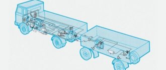
Diagram of the brake system GAZ-3309 diesel
During the design of such a vehicle, the plant's engineers decided to develop its design almost from scratch, which made it unlike other cars of the automaker. The brake system of the GAZ 3309 deserves special mention, which is radically different from its predecessors.
When studying its structure, it is advisable to identify several categories of basic elements that ensure correct operation. These include:
- worker node;
- parking brake equipment;
- spare system.
All of them are designed to quickly brake the truck or slow down its movement. The pneumatic-hydraulic brakes of this vehicle are reliable, which is especially important for freight vehicles, the braking distance of which is critical when dangerous situations arise on the road.
By working unit we mean the main system, which is constantly used while driving, and the spare one is a reserve in case of failure of the first one.
Brake device
Considering the design of this GAZ 3309 system, it should be noted that the standby and backup systems are combined into one set, which should be taken into account when performing repair work. In previous models, the pedal had to be pressed with considerable force to brake, but in the new design, the automaker's engineers managed to completely eliminate this drawback.
The brake design includes the following elements:
- standing brake - clamp, lever-handle, disc, handbrake cable, release element, drum, shoes, related mechanisms;
- drive part - pads, protective caps, pistons, guide brackets, shield, hydraulic cylinder reservoirs, as well as other components;
- brake cylinder - lever body, rod, guide parts, brake light switches.
An important design element is the amplifier, which is designed to increase pressure in key components. Due to this, it becomes possible to significantly increase braking efficiency without the need to exert maximum effort on the controls.
Reviews about GAZ-3309
This page contains a list of the latest (new) reviews from GAZ-3309 owners, as well as the opinions and comments of visitors who are not indifferent to this technology.
I have been working on a GAZ-3309 2004 for 6 years. Mileage – 510 thousand km. There are a lot of problems with the car. If there was an opportunity, I would move to another one or even change my profession.
The brakes are bad, especially in winter (the fluid freezes). Almost every other day you have to install the brake pads and handbrake. It’s the same with the steering - I drive normally only with an empty body in the summer, but in winter it freezes and stops listening.
When you drive, the cabin is still more or less warm, but when you wait for unloading with the engine running, you can freeze. You cannot adjust the engine temperature while driving. The thermostat is completely useless in winter. If you plug the radiator with cardboard, you can boil the engine in mountainous areas.
The gearbox housing is too weak. The gear ratios are chosen quite well.
The engine is snotty. I constantly have to change the rear crankshaft oil seal. Oil and fuel leak from different places. It is very difficult to start at temperatures below -15 degrees.
The truck is rotting terribly. During operation, I changed the fenders twice along with the headlights.
Electrical equipment is generally a problem. I installed new generators three times, and starters twice.
When it rains, water gets into the cabin. In winter, the back wall is covered with “white moss”. You don’t even have to mention sound and heat insulation.
I am engaged in cargo transportation. Two months ago I picked up an onboard GAZ-3309 2011 model. Extended body – 6 m.
Vacuum pump features
An important design element is a vacuum amplifier, which is capable of creating the necessary pressure in the system. Due to this, it is possible to significantly increase braking efficiency, as well as reduce the required force when pressing the pedal. It should be remembered that incorrect operation of this important unit is a dangerous breakdown, leading to unstable operation of the power unit.
This is due to the entry of air into the intake pipe of the engine, which contributes to the leanness of the fuel mixture in its cylinders. As a result, the car cannot operate for a long time and periodically stalls. The design of the system involves the removal of lubricant and mechanical damage to the cylinders in the event of such a malfunction, which is why it is necessary to eliminate it as soon as possible.
Adjusting the parking brake
One of the most important jobs when servicing this vehicle is adjusting the parking brake. It is performed in several stages, and the car enthusiast will only need to have the necessary skills, a 24 mm wrench, and a screwdriver.
The hand brake is adjusted using the following algorithm:
- Lower the lever to the lower position and shift the gearbox to neutral;
- Raise the rear wheel on the left side using a jack, then remove the shield plug.
- Rotate it, turning out the adjusting screw with a screwdriver until it slows down, then unscrew the screw until the wheel rotates freely.
- Install the plug, lower the wheel, and then adjust the mechanism on the right side in the same way.
Brake bleeding technique
Many owners of this car are interested in how to properly bleed the brake system for more efficient operation. This is a pressing problem for many models of domestic trucks, the solution of which requires an integrated approach. You can perform such tuning by following the following instructions:
- Clean the valve mechanisms of the cylinders of each wheel.
- Unscrew the cylinder cover.
- Fill it with the fluid recommended by the manufacturer.
- Bleed the front wheels.
- Remove the brake valve cap, install the hose, and place its other end in a container with brake fluid.
- Unscrew the valve half a turn, then depress the brake pedal several times.
- Screw the valve back and bleed the remaining wheels using a similar method.
When filling brake fluid, it is advisable to remember that its optimal level is 2-3 cm below the maximum recommended level.
GAZ-3309, GAZ-33098. ANTI-LOCK BRAKE SYSTEM
A schematic diagram of the braking system of cars with ABS is shown in Fig. 8.3.
The vehicles are equipped with an anti-lock braking system (ABS). ABS is effective during emergency braking on roads with different surfaces (for example, asphalt-ice) and prevents blocking of wheels located in less favorable traction conditions (on ice), providing a minimum braking distance for the vehicle for a given road surface (ice) while maintaining its stability and controllability.
To obtain the optimal effect when emergency braking a car using ABS, you must press the brake pedal with maximum force while simultaneously pressing the clutch pedal.
The electrical part of the ABS consists of 4 ABS sensors (in the wheel units of the car), 3 modulators (on pneumatic amplifiers), an ABS control unit (CU) (in the cab on the right side), an ABS diagnostic button (on the instrument panel), and an indicator malfunction of the ABS (in the right block of warning lamps) and the ABS harness connecting the sensors and modulators to the ABS control unit.
Two power circuits are connected to the ABS control unit: for the modulators through the 3rd 25A fuse in the ABS fuse block and directly for the ABS control unit through the 1st 5A fuse in the ABS fuse block. The air dryer is powered through the 2nd 10A fuse. The ABS fuse block is located behind a plug located below the fuse block plug.
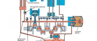
Rice. 8.3 . Schematic diagram of the brake system of cars with ABS:
1 compressor 2 – air dryer with pneumatic regulator 3 – regeneration air cylinder 4 – dual-circuit safety valve 5 – air pressure drop sensor 6 – air cylinder 7 – condensate drain valve 8 – two-section brake valve with lever 9 – ABS rotor speed sensor 10 – brake mechanism with ABS rotor on the hub 11 – electric pressure gauge 12 buzzer 13 – emergency piston stroke and low brake fluid level indicator 14 – ABS indicator 15 – two-section reservoir 16 – pneumatic booster with main cylinder 17 filter 18 – emergency piston stroke sensor 19 – control valve 20 – ABS modulator 21 – ABS control unit 22 – “STOP” signal activation sensor 23 – pressure gauge sensor 24 – “STOP” signal lamp 25 – brake fluid level drop sensor 26 – muffler
The ABS fault warning light comes on for a few seconds each time the instruments are turned on and then goes off, which confirms that the ABS system is working properly. If the warning light is constantly on or comes on while driving, it indicates a malfunction of the ABS.
If the ABS malfunctions, the vehicle must be checked at a service station.
Filling the hydraulic brake drive with brake fluid for vehicles with ABS
Thoroughly clean the bypass valves on the wheel cylinders from dirt.
Unscrew and remove the cap with the emergency brake fluid level drop sensor from the main cylinder refill tank and fill the drive with brake fluid. It is prohibited to fill the hydraulic drive with brake
liquids not provided for in the lubrication card, mineral oils, and also wash it with gasoline or kerosene.
When bleeding the hydraulic brake system, the air cylinders must be filled with air (pressure - 0.6-0.8 MPa (6.0-8.0 kgf/cm2).
Bleed the hydraulic circuit of the front axle service brake. Remove the cap on the bypass valve of the right front brake wheel cylinder, put on a rubber hose, and lower the free end of the hose into brake fluid poured into a glass container.
Unscrew the bypass valve 1/2-3/4 turn and press the brake pedal several times. Pump the hydraulic drive until the release of air bubbles from the hose immersed in a vessel with liquid stops.
Close the bypass valve while pressing the brake pedal.
Bleed the wheel cylinder of the left front brake, performing the work specified in paragraph. 4 and 5.
Bleed the hydraulic circuit of the service brake of the rear axle of the vehicle.
Carry out the work specified in paragraphs. 4 and 5, in the next sequential
right brake mechanism
Add fluid to the additional tank of the main cylinders to a level 32-35 mm below the upper edge of the tank neck and install the cap with the emergency level sensor. During the performance of work specified in clauses. 4-8, it is necessary to add brake fluid to the master cylinder reservoir, avoiding a “dry bottom” in the reservoir reservoirs, otherwise air will enter the system again. Check the pressure in the air cylinders.
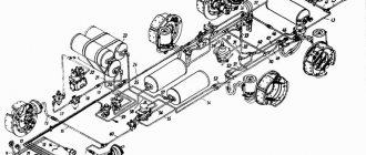
Diagram of the brake system GAZ-3309 (diesel) with an air dryer
The diagram itself is shown in the photo below.
- Compressor installation.
- GC reservoir.
- Emergency sensor.
- Filter.
- Rear wheel braking design.
- Sensor.
- Pneumatic signal switch.
- Muffler.
- Drain tap.
- Braking device for front wheels.
- Critical pressure indicator.
- Air reservoir.
- Check valve.
- Safety single valve.
- Pneumatic booster.
- Modulator.
- Control valve.
- Atmospheric balloon.
- Air dryer.
- Piston sensor.
- Brake valve with two sections.
general description
When designing a truck that was created almost from scratch, it was decided to develop a radically new brake system design. The GAZ-3309 diesel engine was equipped with a design that was independent of previous modifications.
- Working (main) node.
- Parking brake.
- Spare block.
All systems are aimed at one action - reducing the speed or stopping the car completely, depending on the commands given by the driver. An important factor is that for freight transport, the brakes must be as reliable as possible, guaranteeing the vehicle’s stopping in any situation, in order to avoid an accident with serious consequences.
The main system is called that because it is constantly in use while the car is moving. Any brake design consists of a drive and mechanics. The first node is responsible for activating the system at the required period, and the mechanics create resistance to movement.
Management and appointment
The main control element of the brake system of GAZ-3309 vehicles is the foot pedal. It is installed between the clutch and gas analogues. It should be noted that on its predecessors this element had a very tight squeeze. The updated design is completely free of this drawback; the pedal moves softly and smoothly, which is comparable to foreign analogues.
The 3309 truck combines the parking brake and spare brake into one set. This made it possible to reduce the number of components while simplifying the design. The so-called “handbrake” is used to hold the vehicle on a slope when starting off or during long stops. Experienced drivers know that this is an important element, since it is very difficult to catch a loaded car without rolling back, even on a slight slope. Below is the parking brake system of the GAZ-3309 (diesel).
Mechanics
This mechanism consists of a variety of friction parts mounted in direct assembly with the wheel. The parking analogue in this place does not aggregate with the main unit, having a separate structure. It is mounted on the cardan shaft with fixation when turned on. The design and circuit of the GAZ-3309 (diesel) brake system contains drum elements, since they are considered optimal for the type of truck in question. In addition to the drum itself, the design includes fixed blocks of a tape configuration, pressed against it.
The body part interacts closely with the wheel, rotating with it. In the inner part there are brake pads on springs. When you press the pedal, they press against the drum, slowing down its speed. They are fixed to the car hub using a bolt fastening, providing maximum force. The manufacturing material for the pads is a friction alloy that is resistant to abrasion.
Drive part
The drive in the brake system circuit of the GAZ-3309 (diesel) is needed to control the mechanism and then perform certain manipulations. Mechanical and hydraulic operating drives are mounted on the truck, which are responsible for the functioning of the parking and main units. The hydraulic drive was not chosen by chance, as it is considered the best option for a simple truck.
In addition to this modification, there are also drives of pneumatic and electric configurations, which have a narrow specialization and are not used on vehicles of the series in question. Below, for clarity, the figure shows a wheel brake mechanism.
- Brake pad.
- Protection cap.
- Cylinder reservoir.
- Piston.
- Cuff.
- Driven piston.
- Coupling spring.
- Guide bracket.
- Brake shield.
- Washer.
- Screw.
- Finger eccentric.
- Bushings.
- Eccentric plates.
- Tags.
- Observation hatch.
GAZ 3309 steering diagram
The steering diagram of the GAZ-3309 is a steering mechanism with a 3-joint steering column with a splineless connection, which ensures a change in the length of the propeller shaft of the column when the cab oscillates.
GAZ 3309 steering diagram
Steering diagram : 1 - crankcase; 2 - screw with ball nut; 3 - shaft sector; 4 — filler plug; 5 — adjusting shims; 6 - nut; 7 - bolt; 8 - fork; 9 - cover; 10 - wedge; 11 - intermediate support; 12 — middle cardan shaft; 13 — upper casing; 14 — steering wheel; 15 - overlay; 16 - lower casing; 17 - column; 18 — steering lock; 19 — side cover; 20 — lock washer; 21 — adjusting nut; 22 - spacer; 23 , 28 - sealing rings; 24 - plug; 25 - cover; 26 — seal; 27 — bipod; 29 — protective ring; 30 — outer ring of the sector shaft bearing; 31 — retaining ring; 32 - cardan shaft.
GAZ 3309
Peculiarities
We will continue our review of the brake design of GAZ-3307 and 09 trucks by studying a unique alarm system that notifies of brake malfunctions. In addition, the design includes a hydraulic vacuum type amplifier with a reservoir and a shut-off valve. Separate hydraulic circuits are mounted on each vehicle axle. This makes it possible, in the event of failure of one circuit, to ensure the fulfillment of assigned duties, preventing the occurrence of emergency situations.
Balloon tanks are responsible for powering each compartment separately, which is also done for safety reasons. Along the circuits there is a built-in brake force controller, which serves to create the required pressure if one of the circuits breaks down or if equal pressure on each wheel needs to be adjusted. Simply put, the device prevents the pressure force in the working circuit from doubling. At the same time, the pedal travel distance increases, which requires the driver to squeeze it to its maximum.
Wiring and electrical diagram of GAZ 3307
A detailed diagram of the electrical equipment of the GAZ 3307 in maximum equipment includes elements and components:
- Side turn signal mounted on the right front fender.
- Front marker light (right).
- Right headlight.
- Connection strip.
- Left headlight.
- Low beam lamp installed in the headlight.
- High beam lamp.
- Side light bulb.
- Front marker light (left).
- Direction indicator lamp installed in the front position lamp.
- Side turn signal located on the left front fender.
- Coil.
- Spark pulse distributor.
- Candle.
- An additional resistor to eliminate radio interference in the spark plug tip.
- Starter.
- Battery.
- Starter control relay.
- Battery power switch.
- Indicator lamp for activated high beam headlights.
- Upper section of the interior fuse box.
- Klaxon.
- Gas valve solenoid. Installed only on trucks equipped with gas cylinder equipment.
- Electromagnetic element of the gasoline supply valve, used on vehicles with a combined fuel system (gas-gasoline).
- Fuel type switch.
- Ignition system switch.
- An auxiliary relay that turns on the starter.
- Central lighting mode switch.
- Generator.
- Control key for rear fog lamp operation.
- Plug connector.
- Control resistance.
- Additional fuse for autonomous heater. The unit is installed as a separate order.
- An electric motor that ensures the functioning of an independent engine heating system.
- Instrument cluster illumination lamp.
- Cabin lighting.
- Ammeter.
- Voltage regulator unit in the on-board network.
- Autonomous heater control panel.
- Fuel ignition switch in the heater boiler.
- Autonomous operating mode switch.
- An electromagnetic valve that regulates the supply of gasoline to the combustion chamber of an autonomous heater.
- Gas system pressure gauge.
- Coolant temperature sensor.
- Sensor for turning on a lamp warning of overheating of the power plant.
- A sensor that transmits information about the pressure in the lubrication system.
- A separate device that measures critically low pressure in oil lines.
- Ignition switch with built-in contact group.
- Bottom of the interior fuse box.
- A socket designed to connect additional equipment (portable lamp, etc.).
- Alarm control button.
- Starter heater spark plug.
- Second gas system pressure gauge.
- Gasoline level indicator in the fuel tank.
- A control device that displays engine temperature.
- Lubrication system pressure gauge.
- Electric motor to drive the windshield wiper blades.
- Control relay for the glass cleaning system.
- Washer pump drive motor.
- The steering column switch is responsible for selecting the operating modes of the headlights and direction indicators. Additionally, the device is used to provide warning sounds.
- Key for turning on increased fan speed for the standard cabin heating system.
- A similar unit for lower frequency.
- Brake light limit switch.
- Toggle switch for determining the fuel level in different tanks.
- Steering column switch for windshield wiper operating modes.
- A separate indicator displaying the operation of turn signals on towed equipment.
- Indicator lamp for direction indicators on the tractor. When using a single vehicle, only this lamp is active.
- Indicator for turning on side lighting.
- Indicator of the state of the drive of the second circuit of the brake system.
- A similar lamp for the first circuit.
- Indicator lamp for activation of the parking brake and malfunctions in the main circuits.
- Signal unit housing.
- Limit switch for determining the position of the parking brake handle.
- Heater motor on the right side of the cab.
- A similar unit for the left side.
- Measuring fluid level sensor in the hydraulic brake drive.
- A sensor that measures the degree of vacuum in the first brake circuit.
- A similar device for the second circuit.
- Sensor for measuring the amount of fuel in the main tank.
- Switch plate.
- Limit switch in the crankcase box, used to connect the reverse light.
- A contact relay that provides operation of the hazard warning lights and direction indicators.
- Fuel level measurement sensor in the additional tank.
- Back light.
- Socket for connecting electrical equipment on the trailer.
- Fog light mounted on the rear of the truck.
- Reverse lamp.
- Brake warning lamp.
- Dimensional signal.
- Rear direction indicator.
First part
Second part
The third part
Color codes for wires in the diagram:
- B - white;
- K - red;
- F - yellow;
- Z - green;
- Kch - brown;
- Ch - black;
- G - blue;
- O - orange;
- P - pink;
- F - purple;
- C - gray.
The above diagram should be used with caution when repairing used GAZ 3307 trucks. Due to the low corrosion resistance of wiring, owners often replace entire sections with products with different insulation. As a result, difficulties arise during subsequent maintenance.
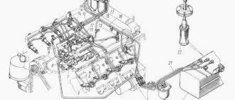
Connection diagram for generator and voltage regulator
The connection diagram for these nodes is no different from other cars. The circuit contains a relay and a separate wire to ensure the operation of the ammeter built into the instrument cluster. The photo shows the circuits connecting the generator to the battery via a discharge relay.
Schematic diagram of generator installation on GAZ 3307
Ignition system electrical circuit
The truck is equipped with a battery-based contactless ignition system with a transistor switch, consisting of the following components:
- coils;
- pulse distributor;
- individual candles;
- connecting wires.
The ignition is activated by turning the key in the lock. The distributor ensures that pulses are sent to the spark plugs at 45 degrees. with a deviation of the moment of signal delivery within 1 degree. The components include elements that reduce the level of radio interference during operation.
Components of the ignition system on a gasoline car GAZ 3307
The system includes:
- permanent magnet;
- noise suppression resistor R in the spark plug tip (5.5 kOhm);
- additional resistances R1-R15 with different ratings;
- capacitors C1-C11;
- transistors VT1 and VT2;
- diodes and zener diodes;
- control microcircuit KR1055HP1 or KS1055HP1 (indicated D in the diagram);
- switch D1;
- throttle L;
- primary winding L1 of the ignition coil;
- secondary winding L;
- coil;
- 60A protective fuse (on the engine compartment panel);
- candles;
- ammeter P;
- ignition switch S;
- battery breaker S1;
- battery G;
- pulse sensor (indicated B in the diagram).
Checking the functionality of the switch is shown in a video from the “Autoelectrics HF” channel.
Fuse diagram for GAZ 3307
On trucks with gasoline engines there are two PR-121 type pads located in the passenger compartment. The units are located in the central part of the instrument panel, secured to the frame using two self-tapping screws. The pads are designed to use older cylindrical configuration inserts.
Fuse layout diagram in the GAZ 3307 cabin
Fuse rating in the upper section with a description of the protected components and circuits:
| Number | Allowable current, A | Purpose |
| Pv-01 | 16 | Reserve insert, for replacement |
| Pv-02 | 8 | Engine compartment lighting and cabin light |
| Pv-03 | 8 | Instrument and switch combination lamps |
| Pv-04 | 8 | Power supply for fog lamp on stern |
| Pv-05 | 8 | Right front and left rear dimensions, as well as the indicator light for turning on the side lights |
| Pv-06 | 8 | Left front and right rear parking signal |
| Pv-07 | 8 | Left side low beam |
| Pv-08 | 8 | Likewise for the starboard side |
| Pv-09 | 16 | High beam on the left side and indicator for turning on this mode |
| Pv-10 | 16 | Same for the right side |
The lower section contains:
| Number | Allowable current, A | Purpose |
| Mon-01 | 16 | Spare part |
| Mon-02 | 8 | Alarm protection |
| Mon-03 | 8 | Direction indicators |
| Mon-04 | 8 | Reserve part |
| Mon-05 | 8 | Horn and socket for installing additional equipment |
| Mon-06 | 8 | Brake lamps |
| Mon-07 | 8 | Spare element |
| Mon-08 | 8 | Windshield cleaning and washer fluid supply system |
| Mon-09 | 16 | Reverse gear lamp and gas system |
| Mon-10 | 16 | Additional heater, elements of the instrument cluster (including warning lights) |
There are several other fuses installed on the truck:
- To protect the control circuits for ignition and operation of an additional autonomous heater. The insert has a rating of 20A and is located directly inside the control panel.
- The glass cleaning system is equipped with a bimetallic reusable part. When overheated, the element opens, protecting the drive. After cooling, the functionality of the unit is restored.
- There is a 60A fuse in the engine compartment (on the right side of the panel) for the general electrical of the truck. The device does not provide protection for the generator set.
- An additional 30A insert is installed nearby, used as a backup.
The operating instructions for the GAZ 3307 vehicle allow the use of copper conductors with the following parameters instead of fuses:
| Current strength, A | Wire diameter, mm |
| 6 | 0,18 |
| 8 | 0,23 |
| 16 | 0,34 |
| 30 | 0,5 |
| 60 | 0,8 |
Installation of homemade inserts in the electrical circuit of the GAZ 3307 is possible only for short-term use. Due to difficulties in determining the parameters of the wire, an excessive increase in current strength and failure of consumers occurs.
Brake cylinder
A complete review of the brake design of the GAZ-3307 and 09 truck should include a study of the features of the main brake cylinder. It is activated by pressing the pedal, creating the required pressure in the circuit through small pistons. This element is halved for each contour. Floating head pistons are a modification of the bypass valve. During the free state of the pedal, the TC is connected to the expansion tank.
When you press the pedal, the pistons begin to move, sit in place and close tightly. Accordingly, the interaction between the TC and the tank stops. During normal daily operation of the truck, the brake mixture level is close to the maximum level, especially with new pads and the indicator removed. Below is an image of a brake valve, which you cannot do without when converting the brake system of the GAZ-3309.
- Lever body.
- Paired lever.
- Fixing bolt.
- Cam.
- Working traction.
- Guide element.
- Rod for trailer section.
- Diaphragm.
- Valve seat.
- Intake valve.
- Exhaust valve.
- Stop switch.
- Signal switch.
- Diaphragm.
- Stock.
- Frame.
Possible malfunctions of the pneumatic drive of brake mechanisms and ways to eliminate them
1. The pneumatic system receivers are not filled or are filled slowly (the pressure regulator is activated)
Damage to hoses and pipelines
Replace hoses and pipelines
Loosening the connections of pipelines, hoses, connecting and transition fittings
Tighten connections, replace faulty connection parts and seals
Loosening the tightening of body parts of devices
Tighten the fastening of the body parts
Receiver leakage
2. The pressure regulator often operates when the pneumatic system receivers are full
Leakage of compressed air in the line from the compressor to the 4-circuit safety valve
Eliminate the leak using the methods specified in paragraph 1
3. The pneumatic system receivers are not filled (the pressure regulator is activated)
Pressure regulator incorrectly adjusted
Adjust the pressure regulator using the adjusting screw; if necessary, replace the pressure regulator
The pipelines in the area from the pressure regulator to the 4-circuit safety valve are clogged
Inspect the pipelines. If necessary, remove and blow. If the pipeline is incorrectly bent (there is a kink), replace it
4. Receivers of circuits I and II are not filled
The 4-circuit safety valve is faulty
Replace faulty valve
Supply pipes are clogged
Supply pipes are clogged
Blow out the pipelines with compressed air. Replace if necessary
5. The pressure in the receivers of circuits I and II is higher or lower than normal when the pressure regulator is working
The two-pointer pressure gauge is faulty
Replace two-pointer pressure gauge
The pressure regulator is not adjusted correctly
Adjust the pressure regulator using the adjusting screw. If necessary, replace the pressure regulator
6. Ineffective braking or lack of braking of the KamAZ 4308 vehicle by the working brake system when the brake pedal is fully pressed
Significant leakage of compressed air in the lines of circuits I and II in the area behind the brake valve
Eliminate the leak using the methods specified in paragraph 1
The adjustment of the brake valve drive is broken
Adjust the brake valve drive
Incorrect installation of the brake force regulator drive
Adjust the installation of the brake force regulator drive or replace the brake force regulator
7. Ineffective braking or lack of braking of the vehicle by the parking brake system when the parking brake system control valve is activated
The accelerator valve, the parking brake system control valve, and the emergency brake release valve are faulty
Replace faulty brake system
The pipelines or hoses of the third circuit are clogged
Clean the pipelines and blow them out with compressed air. If necessary, replace with working ones
Spring energy accumulators are faulty
Replace faulty brake chambers with spring energy accumulators
The stroke of the brake chamber rods exceeds the established value
Adjust the stroke of the rods
8. When installing the parking brake system control valve handle in a horizontal position, the car does not release the brakes
Air leakage from the pipelines of the third circuit, from the atmospheric outlet of the accelerator valve
Eliminate the leak using the methods specified in paragraph 1
9. When the vehicle is moving, the rear bogie brakes without actuating the brake pedal and the parking brake system control valve.
The two-section brake valve is faulty. The brake valve drive is incorrectly adjusted
Replace the tap. Adjust the brake valve drive
The seal between the cavity of the spring energy accumulator and the working chamber is broken
Replace the brake chamber with spring energy accumulator
Eliminate the leak using the methods specified in paragraph 1
Remove the pipelines and blow them out with compressed air.
10. When the brake pedal is pressed or when the parking brake system is applied, the brake lights do not light up
The sensor for turning on the brake signal lights of the pneumatic drive devices is faulty
Replace faulty sensor or devices
11. Presence of a significant amount of oil in the pneumatic system
Source
Amplifier
This element is needed in order to create additional pressure in the circuits of the unit. This makes it possible to improve the quality of braking of the car, without requiring maximum effort to press the pedal. The principle of operation of the hydraulic vacuum booster is based on creating additional pressure in the inlet part of the power unit, which causes a similar effect in the TC.
If the mechanism breaks down, the quality of braking deteriorates sharply, since a constant flow of air is supplied to the engine intake pipe. This contributes to the leanness of the fuel mixture in some of the cylinders. For this reason, the car may stall. At the same time, it will be possible to start it only after repairing the brake system of the GAZ-3309 (diesel). The circuit is designed in such a way that in the event of this malfunction, the unburned mixture removes the lubricant and scratches the cylinder mirror.
Not available:
| № | Part code | Name | Part Information |
| 200273-P29 | Bolt M8-6gх70 | Quantity per 3309 2 Galvanizing and passivation coating (zinc with chromating) | Not available |
| 201415-P29 | Bolt M6-6gx10 OST 37.001.123-96 | Quantity per 3309 40 Galvanizing and passivation coating (zinc with chromating) | Not available |
| 201453-P29 | Bolt M8-6gх14 | Quantity per 3309 9 Galvanizing and passivation coating (zinc with chromating) | Not available |
| 220058-P29 | Screw M4-6gx25 OST 37.001.127-81 | Quantity per 3309 18 Galvanizing and passivation coating (zinc with chromating) | Not available |
| 25-6411-1302 | Belt (1-8.5x8x933) | Not available | |
| 250510-P29 | Nut M8-6N OST 37.001.124-93 | Quantity per 3309 213 Galvanizing and passivation coating (zinc with chromating) | Not available |
| 251082-P29 | Nut M4-6N OST 37.001.112-91 | Quantity per 3309 30 Galvanizing and passivation coating (zinc with chromating) | Not available |
| 290775-P29 | Bolt M10-6gx40 | Quantity per 3309 12 Galvanizing and passivation coating (zinc with chromating) | Not available |
| 297282-P | Gasket diameter 22 plugs assembled | Quantity per 3309 2 Coating without coating | Not available |
| 297406-P29 | Clamp 20 | Quantity per 3309 10 Galvanizing and passivation coating (zinc with chromating) | Not available |
| 31011-3407230 | Retaining ring | Quantity for 3309 1 Model 31011 Group Steering control Subgroup Power steering pump Part number 230 | Not available |
| 3306-3548010-10 | Vacuum pump | Quantity per 3309 1 Model 3306 Group Brakes Subgroup 3548 Serial part number 010 Additionally Not interchangeable with a part previously released under the same number | Not available |
| 3306-3548015-10 | Vacuum pump housing | Quantity for 3309 1 Model 3306 Group Brakes Subgroup 3548 Serial part number 015 Additionally Not interchangeable with a part previously released under the same number | Not available |
| 3306-3548020 | Union | Quantity per 3309 1 Model 3306 Group Brakes Subgroup 3548 Part number 020 | Not available |
| 3306-3548025 | Rotor blade | Quantity per 3309 4 Model 3306 Group Brakes Subgroup 3548 Part number 025 | Not available |
| 3306-3548030-10 | Rotor | Quantity for 3309 1 Model 3306 Group Brakes Subgroup 3548 Serial part number 030 Additionally Not interchangeable with a part previously released under the same number | Not available |
| 3306-3548034-10 | Flange | Quantity for 3309 1 Model 3306 Group Brakes Subgroup 3548 Serial part number 034 Additionally Not interchangeable with a part previously released under the same number | Not available |
| 3306-3548038 | Sleeve | Quantity for 3309 1 Model 3306 Group Brakes Subgroup 3548 Part number 038 | Not available |
| 3306-3548044-10 | Rotor roller | Quantity for 3309 1 Model 3306 Group Brakes Subgroup 3548 Serial part number 044 Additionally Not interchangeable with a part previously released under the same number | Not available |
| 3306-3548050 | Plank | Quantity per 3309 1 Model 3306 Group Brakes Subgroup 3548 Part number 050 | Not available |
| 3306-3548060 | Pulley | Quantity per 3309 1 Model 3306 Group Brakes Subgroup 3548 Part number 060 | Not available |
| 3306-3548062 | Pulley | Quantity per 3309 1 Model 3306 Group Brakes Subgroup 3548 Part number 062 | Not available |
| 3306-3548064 | bracket | Quantity per 3309 1 Model 3306 Group Brakes Subgroup 3548 Part number 064 | Not available |
| 3306-3548100 | Hose | Quantity per 3309 1 Model 3306 Group Brakes Subgroup 3548 Part number 100 | Not available |
| 3306-3548102 | Sleeve | Quantity per 3309 1 Model 3306 Group Brakes Subgroup 3548 Part number 102 | Not available |
| 3306-3548180-10 | Vacuum pump cover | Quantity per 3309 1 Model 3306 Brake group Subgroup 3548 Part serial number 180 Additionally Not interchangeable with a part previously released under the same number | Not available |
| 3306-3548202 | Adapter | Quantity per 3309 1 Model 3306 Group Brakes Subgroup 3548 Part number 202 | Not available |
| 3306-3548282 | Cuff 24x40-7 | Quantity per 3309 1 Model 3306 Group Brakes Subgroup 3548 Part number 282 | Not available |
| 41-3224087 | Ring sealing | Quantity per 3309 1 Model 41 Subgroup 3224 Part number 087 | Not available |
| 4301-1015065 | Pad | Quantity for 3309 11 Model 4301 Group Engine Subgroup Starting engine heater Part number 065 | Not available |
| 4301-1601300 | Conical spring washer | Quantity per 3309 120 Model 4301 Group Clutch Subgroup Clutch Part number 300 | Not available |
| 4301-1601301 | Washer 10x20 conical | Quantity per 3309 81 Model 4301 Group Clutch Subgroup Clutch Part number 301 | Not available |
| 45-9952-3092 | Hairpin M8x1-4hx75 | Not available | |
| 45-9952-6738 | Washer 10 | Not available | |
| 542-1022010 | Fuel pipe | Quantity per 3309 3 Model 542 Group Engine Subgroup Thermal start aid device Part serial number 010 | Not available |
| 542-1022032 | Bolt M10x1-6gx24 | Quantity per 3309 3 Model 542 Group Engine Subgroup Thermal start aid device Part serial number 032 | Not available |
| 542-1022044 | Square | Quantity per 3309 2 Model 542 Group Engine Subgroup Thermal start aid device Part serial number 044 | Not available |
| 70-10003 | Clamp clamp | Quantity per 3309 2 | Not available |
Principle of operation
After pressing the pedal, the hydraulic vacuum amplifier catches this maneuver, repeatedly increasing the force, forwarding it to the main TC of the vehicle. On the working circuits, the piston elements increase the fluid pressure in accordance with the force of pressing the pedal. In this case, the pressure force increases sharply, the working cylinders of the wheels displace the pads in the vehicle drums.
If the pedal continues to move, the force increases further, after which the mechanisms are fully brought into working condition. The pads, engaging with the drum elements, slow down the rotation of the wheels with maximum force where the wheel comes into contact with the road. The braking force is counteracted by its rotational counterpart, causing the car to slow down.
To resume movement, the driver removes his foot from the pedal, after which the return spring mechanism returns it to the free position. Following this element, the TC pistons are released. The pads move away from the surface under the force of special springs. Excess lubricant is squeezed out through the open heads and fed into the expansion tank. In this case, the pressure indicator is reduced to a minimum.
How to bleed the brakes on a GAZ-3309?
The system is bled as follows:
- The bypass valves on the wheel cylinders are well cleaned.
- Unscrew the filling cap of the main cylinder tank (master cylinder).
- Fill the reservoir with brake fluid. It is necessary to fill in the composition specified in the operating instructions.
- The pressure in the air cylinders should correspond to 0.6-0.8 MPa.
- Bleed the hydraulic drive circuit of the front wheels.
- Remove the bypass valve cap of the right front brake, put on a rubber hose, lower its free edge into the brake fluid, previously poured into a glass container.
- Unscrew the bypass valve half a turn and depress the brake pedal several times. The hydraulic drive is pumped until bubbles stop appearing in the vessel into which the rubber hose is lowered.
- Tighten the bypass valve while pressing the pedal.
- Pump the TC of the left front wheel in a similar way.
- The operation is performed with the rear-wheel drive elements using the same method.
- Bleeding is performed in the above sequence.
- Brake fluid is added to the main fluid reservoir. The level should be 1-2 centimeters below the maximum indicator on the neck of the tank.
When performing this operation, it is necessary to add working fluid without allowing the bottom of the tank to dry out.
VESKO-TRANS.RU
AutoNews / Reviews / Tests
- Home
- Auto garage
- How to Bleed Brakes on Gas 3309
How to Bleed Brakes on Gas 3309
Gas-car brake system 3309 , 3308, GAZ-33081 Sadko
Cars GAZ 3309 , 3308, GAZ-33081 Sadko is equipped with 3 brake systems:
— control of wear of wheel brake linings through two holes in the brake panels, closed with removable plugs;
— a system that notifies the driver when the parking brake system is applied;
A schematic diagram of the service brake system is shown in Fig. 1.
— Disconnect the air supply hose from the compressor and disconnect the oil supply hose.
— Unwind three nuts and one bolt securing the compressor to the engine and remove the compressor.
— Secure the compressor vertically to crankcase 2 under pressure (see Fig. 3).
- Remove the intake and exhaust valves.
As a pump, it slows down alone, without outside help.
I've used this simple method for years. I will add that when filling an empty system, it is recommended to first.
Problems with brakes, gas 3309.
obstacles with brakes, gas 3309.
— Press the lock ring 10 and the piston pin 9.
— Unscrew the mounting bolts and remove the side cover 12;
— Press pin 15 and pull pin 16, keeping pin 17 from falling.
The brake drive uses three unified master cylinders: one in the hydraulic drive for the front brakes, two. to the back.
— disconnect the hose or pipe from the brake cylinder;
— unscrew the exhaust valve from the cylinder;
— Lubricate the surface of the parts with a thin layer of Litol lubricant.
— Measure the position of the air booster pusher using a caliper.
- Connect the master cylinder to the pneumatic booster, the torque of the nut is 2.4-3.6 kg/cm.
— Attach the mount to the pneumatic module of the amplifier of the modulator cylinder.
The need for replacement is determined by the formation of condensation in the air cylinders. The accumulation of huge amounts of condensate in the pneumatic actuators of the brake drive can lead to their failure.
It is necessary to monitor the condition of the faucet's protective casing and its tightness in relation to the body, since dirt getting on the lever system and the cleaning surfaces of the faucet leads to malfunction.
The freewheel pedal with the service brake valve should be 20-25 mm.
Service
Preventive measures for servicing the brake system include periodic inspection of connections and seals for bleeding, reliability of fastening, and general condition of the unit. To avoid frequent repairs of GAZ-3309 brakes, you should regularly change the air dryer cartridge. In addition, in winter, you need to monitor the drainage of condensate to prevent it from freezing. It is also necessary to pay attention to the tight fit of the faucet cover to the body and its condition. The tightness of the mechanism is checked using a soap composition.
Source
TRUCKS GAZ, ZIL, KAMAZ, URAL, MAZ, KRAZ
_________________________________________________________________________________________
Elements of the brake system of GAZ-3309, 3308 cars
Cars GAZ-3309, GAZ-3308, GAZ-33081 Sadko are equipped with three brake systems: - a working one, acting on the brake mechanisms of all wheels of the car; — a spare one, which is part of the working brake system and acts on the brake mechanisms of the front or rear wheels; — parking, acting on the brake mechanisms of the rear wheels. The brake systems of GAZ-3309, GAZ-3308, GAZ-33081 Sadko vehicles provide for: - monitoring the brake fluid level in the supply tank of the brake master cylinder, for which a float sensor is installed in the tank for an emergency drop in the brake fluid level; — control over the degree of pumping of the hydraulic drive;
— monitoring the wear of wheel brake linings through two holes in the brake shields, closed with removable plugs; — monitoring the pressure in the pneumatic part of the brake drive, for which pressure sensors are installed in the air cylinders, and pressure gauges are installed on the instrument panel;
— a system that notifies the driver that the parking brake system is engaged; — a sound system that notifies the driver of an emergency drop in air pressure in the pneumatic drive. The service braking system is designed with separate axle braking (with two independent circuits), with each circuit serving as a backup braking system.
A schematic diagram of the service brake system is shown in Fig. 1. The brake control includes wheel brake mechanisms and their drive.
The drive includes a two-section brake valve, ABS modulators, pneumatic boosters with brake master cylinders, air cylinders with check valves, an air dryer, a compressor, as well as hydraulic and air tubes that functionally connect these units.
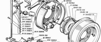
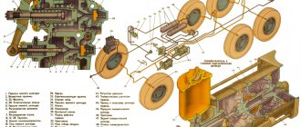
Rice. 1. Schematic diagram of the brake system GAZ-3309, GAZ-3308, GAZ-33081 Sadko 1 - compressor; 2 - air dryer; 3 — regeneration air cylinder; 4 - check valve; 5 — air pressure drop sensor; 6 — air cylinder; 7 — condensate drain valve; 8 — two-section brake valve with a lever; 9- lever of the parking brake system (STS); 10 — ABS speed sensor; 11 — ABS rotor; 12 — electric pressure gauge; 13 — buzzer; 14-indicator for emergency piston stroke and drop in brake fluid level; 15 — ABS indicator; 16 — STS activation indicator; 17 — two-section tank; 18 — pneumatic booster with the main cylinder; 19 — filter; 20 — emergency piston stroke sensor; 21 — control valve; 22- ABS modulator; 23 – ABS control unit; 24 — sensor for switching on the “STOP” signal; 25 — pressure gauge sensor; 26 — “STOP” signal lamp; 27 — brake fluid level drop sensor; 28 — silencer; 29 — STS activation indicator sensor The working brake system of GAZ-3309, GAZ-3308, GAZ-33081 Sadko must ensure effective braking of the vehicle without skidding and loss of control. The braking distance of a vehicle at full load, moving at a speed of 60 km/h on a flat section of a dry highway, with the brake pedal fully depressed, should not exceed 36.7 m. The spare brake system should provide a stopping distance of no more than 51 m under the conditions described in the requirements for the service brake system. The brake mechanisms of the front and rear wheels of GAZ-3309, GAZ-3308, GAZ-33081 Sadko are identical in design and differ in the size of a number of included parts. The brake mechanisms of the front wheels are equipped with cylinders with pistons with a diameter of 35 mm and linings with a width of 80 mm. The brake mechanisms of the rear wheels have cylinders with pistons with a diameter of 38 mm and linings with a width of 100 mm, as well as additional drive parts for the parking brake system. The structure of the wheel brake mechanism is shown in Fig. 2. The pads are fixed relative to the brake drum using eccentric support pins 12. Each pad is secured independently of the other.
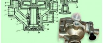
Rice. 2. Wheel brake mechanism GAZ-3309, GAZ-3308, GAZ-33081 Sadko 1 - brake pad; 2 — protective cap; 3 - cylinder body; 4 — piston with sleeve and rod; 5 - cuff; 6 — driven piston; 7 — tension spring of pads; 8 — guide bracket of pads; 9 — brake shield; 10 - spring washer; 11 - nut; 12 — eccentric pin of the brake pad; 13 — eccentric pin bushings; 14 - plate of eccentric fingers; 15 — marks; 16 — inspection hatch At the outer end of each support pin there is a mark (a recess with a diameter of 2 mm) showing the position of the greatest eccentricity of the adjusting pin. When the pads are installed correctly, when the friction linings and brake drum are not worn out, marks 15 should face one another, as shown in Fig. 2, or with a deviation from this position within 40°. Wheel brake cylinders GAZ-3309, GAZ-3308, GAZ-33081 Sadko have a device that automatically maintains the required gap between the friction lining and the drum. During operation, no special adjustment is required. The car compressor is piston type, single cylinder, air cooled. Rice. 3. Compressor of a GAZ-3309, GAZ-3308, GAZ-33081 car 1 - crankshaft; 2 - crankcase; 3 — connecting rod; 4 - cylinder; 5 — inlet valve; 6 - discharge valve; 7 — cylinder head; 8 — valve plate; 9 — piston pin; 10 - retaining ring; 11 - piston; 12 - cover; 13 - spring; 14 - bushing; 15 - pin; 16 - axis; 17 – gear Air from the engine intake pipe enters the compressor cylinder through the reed inlet valve. Compressed air is forced into the pneumatic system through a plate discharge valve. Compressor lubrication comes from the engine lubrication system. The compressor drive is belt driven. The compressor (Fig. 3) is piston type, single-cylinder, air-cooled, with a gear drive. Disassembling the compressor GAZ-3309, GAZ-3308, GAZ-33081 Sadko - Disconnect the air exhaust pipe from the compressor.
— Disconnect the air supply hose to the compressor and disconnect the oil supply hose. — Unscrew the bolt securing the hose coupling and remove the gaskets.
— Unscrew the three nuts and one bolt securing the compressor to the engine and remove the compressor. — Place the compressor on a workbench and remove the connecting rod cover by unscrewing the two nuts.
— Secure the compressor vertically in a vice to crankcase 2 (see Fig. 3). — Unscrew the four tie rod nuts, remove head 7, valve plate 8 and cylinder 4 from crankcase 2.
- Remove the intake and exhaust valve plates. — Remove connecting rod 3 with piston from the cylinder
— Compress and remove retaining ring 10 and piston pin 9 from the piston. — Remove the piston rings.
— Unscrew the fastening bolts and remove the side cover 12; — Remove bushing 14, spring 13 and crankshaft 1 with bearings.
— Press out pin 15 and remove axle 16, holding drive gear 17 from falling. Two-section brake valve GAZ-3309, GAZ-3308, GAZ-33081 Sadko The two-section brake valve (Fig. 4) is designed to control the pneumatic boosters of the vehicle's service brake system.
The brake valve has two independent sections, located in series and powered by separate circuits. The faucet valves are flat, single, rubber.
Fig.4. Two-section brake valve GAZ-3309, GAZ-3308, GAZ-33081 Sadko with lever V1, V2, Z1, Z2 - conclusions; 1 - lever: 2 - roller; 3 - elastic element; 4 - base plate; 5 - upper piston; 6 — upper body; 7 - large piston; 8 - small piston; 9 — lower body; 10 — exhaust valve; 11, 13, 14, 16 - springs; 12 — valve of the lower section; 15 — valve of the upper section; 17 - plate; 18 — hairpin; 19 — pusher; 20 — roller axis; 21 — cover; 22 - lever The connection points of the pipelines are marked with two numbers: terminals “11” and “12” (VI and V2 in the figure) are connected to air cylinders, terminals “21” and “22” (Z1 and Z2 in the figure ) - with pneumatic brake boosters through ABS modulators. In the initial position (brake pedal released), terminals Z1 and Z2 are connected to the atmosphere, and valves disconnect terminals V1 and V2 from terminals Z1 and Z2. When you press the brake pedal, terminals Z1 and Z2 are disconnected from the atmosphere, and the valves of the upper and lower sections open. Compressed air flows from terminals VI and V2 to terminals Z1 and Z2 respectively. If the upper section of the brake valve fails, the lower section is controlled mechanically through a pin and a small piston pusher, fully maintaining its functionality. The car has three modulators that act as air pressure relief valves in the pneumatic amplifiers when they receive a signal from the ABS control unit that the braking force on the wheels has reached a critical value that can cause them to lock. The pneumatic brake booster GAZ-3309, GAZ-3308, GAZ-33081 Sadko (Fig. 5) is connected to the main brake cylinder and is designed to create the required fluid pressure with compressed air in the hydraulic part of the drive of each circuit. The emergency piston pusher and the sensor itself are located in the front wall of the pneumatic booster housing.
Rice. 5. Pneumatic brake booster GAZ-3309, GAZ-3308, GAZ-33081 Sadko with master brake cylinder 1 - plate; 2 — overpressure valve; 3 - spring; 4 - cuff; 5 - thrust rod; 6 - sealing end ring; 7 — pusher; 8 - sealing ring; 9 — pneumatic booster housing; 10- clamp; 11 - cover; 12 - membrane; 13 — emergency piston stroke sensor; 14 — pusher; 15-piston; 16 - thrust bolt; 17 — main cylinder housing; 18 — piston head; 19 — spring The sensor of each circuit is activated when the pusher stroke is 29.7-32.3 mm in the event of depressurization of the brake hydraulic drive line, in the presence of air in the hydraulic brake drive and in case of large wear of the brake linings.
At the same time, the service brake fault indicator lights up in the instrument cluster. When braking, compressed air from the two-section brake valve GAZ-3309, GAZ-3308, GAZ-33081 Sadko flows through the fitting in the cover to the pneumatic booster membrane.
Under air pressure, the membrane moves the rod, which, through a pusher, acts on the piston of the main brake cylinder, displacing brake fluid into the hydraulic line. When the brakes are released, air from the pneumatic booster escapes into the atmosphere through a two-section brake valve. The pneumatic booster rod returns to its original position under the action of a spring. To clean the atmospheric air entering the pneumatic amplifier when the rod returns, a filter is screwed into each amplifier. The control output valves are located at the entrance to the ABS modulators and are designed to connect control and measuring instruments to them when checking the compressed air pressure. To connect to the valve, it is necessary to use a hose and measuring instruments with union nuts M1bx1.5. Check valves are installed on 20 liter air cylinders and are designed to maintain air pressure in the air circuits in the event of a drop in air pressure in the supply line. Main brake cylinder GAZ-3309, GAZ-3308, GAZ-33081 Sadko Main brake cylinder GAZ-3309, GAZ-3308, GAZ-33081 Sadko (see Fig. 5) is connected to the pneumatic booster with three studs. A pneumatic booster with a master cylinder is installed on the frame.
The brake drive uses three unified master cylinders: one in hydraulic drive to the front brake mechanisms, two to the rear. In the cylinder body 17 there is a piston 15 with a head 18 and an overpressure valve 2. The head is held on the piston using a thrust rod 5, which is pressed into the piston. A sealing end ring b and a cuff 4 are installed on the head, and an o-ring 8 is installed on the piston. The head is pressed against the piston by spring 3, and the piston assembly with the head and seals is pressed against the thrust bolt 16 by return spring 19. The maximum stroke of the piston is 38 mm. The main brake cylinder is connected to the supply tank through an adapter fitting and pipelines.
In the released position, the piston 15 of the main cylinder through the head 18 rests against the bolt 16, as a result of which a gap is formed between the piston and the head for the passage of fluid from the tank into the working cavity of the cylinder. When braking, the pusher 7 of the pneumatic booster moves the piston 15. In this case, the head 18, under the action of the spring 3, is pressed through the sealing ring 6 to the piston, separating the liquid in the tank from the liquid in the working cavity of the cylinder. When the piston moves, liquid from the working cavity of the main brake cylinder GAZ-3309, GAZ-3308, GAZ-33081 Sadko passes through the holes in the plate 1 of the excess pressure valve 2 and, pressing the rubber belt of the valve from the plate, enters the pipeline going to the wheel cylinders. When the brake is released, the piston 15, under the action of the return spring 19, moves to its original position until the head 18 rests on the bolt 16.
If the brake pedal is released abruptly, the brake master cylinder piston returns faster than fluid from the wheel cylinders. In this case, a vacuum is created in the working cavity of the main cylinder, under the influence of which the head moves away from the piston, forming an end gap, and liquid from the tank fills the working cavity of the cylinder. When the piston rests on bolt 16, excess fluid returns through the end gap to the master cylinder reservoir. The system is released and ready for further braking. Anti-lock braking system (ABS) of GAZ-3309, GAZ-3308, GAZ-33081 Sadko cars GAZ-3309, GAZ-3308, GAZ-33081 Sadko cars are equipped with an anti-lock braking system (ABS). ABS is effective during emergency braking on roads with different surfaces (for example, asphalt-ice) and prevents wheel locking in less favorable traction conditions (on ice), providing a minimum braking distance for the vehicle for a given road surface (ice) while maintaining its stability and controllability. The electrical part of the ABS consists of 4 ABS sensors (in the wheel units of the car), 3 modulators (on pneumatic amplifiers), an ABS control unit (CU) (in the cab on the right side), an ABS diagnostic button (in the instrument cluster), an ABS fault indicator and a harness ABS, connecting sensors and modulators to the ABS control unit. Two power circuits are connected to the ABS control unit: for the modulators through the 3rd 25 A fuse in the fuse block and directly for the ABS control unit through the 1st 5 A fuse in the fuse block. The air dryer is powered through the 2nd 10 A fuse. The ABS fuse block is located behind a plug located below the fuse block plug.
Fig.6. Electrical diagram of ABS cars GAZ-3309, GAZ-3308, GAZ-33081 Sadko The ABS malfunction indicator lights up for a few seconds each time the ignition is turned on, and then goes off, which confirms the serviceability of the system. If the warning light is constantly on or comes on when the vehicle is moving, it indicates a malfunction of the ABS. The electrical circuit of the ABS is shown in Fig. 6.. Wheel brake cylinder GAZ-3309, GAZ-3308, GAZ-33081 Sadko. Removing the wheel brake cylinder GAZ-3309, GAZ-3308, GAZ-33081 Sadko in the following order: - remove the wheel and brake drum. Separate the brake pads by removing the tension springs that tighten them;
— disconnect the hose or pipeline from the brake cylinder; — Unscrew the brake cylinder mounting bolts. Disassembling the wheel brake cylinder - remove the rubber protective covers from the wheel cylinder, turn one of the pistons 90° and remove the pistons from the cylinder. Remove the rubber protective covers and cuffs from the pistons;
— unscrew the bleeder valve from the cylinder; - wash the wheel cylinder and its parts in pure isopropyl alcohol or brake fluid, then dry with compressed air. Assembling the pneumatic brake booster for GAZ-3309, GAZ-3308, GAZ-33081 Sadko - Wash the metal parts in kerosene and dry them.
— Lubricate the rubbing surfaces of the parts with a thin layer of Litol lubricant. — Assemble the pneumatic booster in the reverse order of disassembly.
— Using a caliper, measure the position of the brake booster rod pusher. — Using saponification, check the working cavity of the pneumatic booster for leaks, supplying compressed air to the fitting in the cover of the pneumatic booster; air leaks are not allowed. Assembling the pneumatic brake booster GAZ-3309, GAZ-3308, GAZ-33081 Sadko with the main brake cylinder The assembly procedure is as follows: - Before assembly, measure the depth of the recess in the piston of the main brake cylinder with a caliper, determine the gap between the piston of the main brake cylinder and the rod pusher of the pneumatic brake booster, which should be within (1.5±0.5) mm. — If necessary, adjust the position of the pneumatic booster rod pusher.
— Connect the main cylinder with the pneumatic booster, the tightening torque of the nuts is 2.4-3.6 kg/cm. — Install the modulator in the cover and the air filter on the housing.
— Attach the brackets to the pneumatic booster-main cylinder-modulator module. The most likely malfunctions of the brake master cylinder are wear of the seals, rubber sealing rings, pistons, piston heads, scuffing and wear of the working surface. The master brake cylinder is removed from the vehicle together with the pneumatic booster. Maintenance of brakes of GAZ-3309, GAZ-3308, GAZ-33081 Sadko cars During the operation of the GAZ-3309, GAZ-3308, GAZ-33081 Sadko cars, they periodically check (daily maintenance) the brake fluid level in the supply tank, the tightness of the pneumatic and hydraulic parts of the brake drive, as well as the serviceability of the service brake system and the operability of the parking system. When servicing the pneumatic part of the drive, it is necessary to monitor the tightness of the system as a whole and its individual elements. Places of air leakage are determined by ear or soap emulsion. Air leaks in connections are eliminated by tightening or replacing individual elements. To ensure normal operation of the pneumatic drive, it is necessary to regularly change the removable air dryer cartridge.
The need for replacement is determined by the formation of condensation in the air cylinders. The accumulation of large amounts of condensate in the pneumatic devices of the brake drive can lead to their failure. In winter, the drainage of condensate must be monitored especially carefully to avoid freezing in devices and pipelines; if condensate freezes, it is prohibited to warm up devices, pipelines and cylinders with an open fire. It is necessary to use hot water for this purpose. Maintenance of the two-section brake valve GAZ-3309, GAZ-3308, GAZ-33081 Sadko consists of periodic inspection, cleaning of dirt, checking the reliability of the valve’s fastening and checking its operation.
It is necessary to monitor the condition of the protective cover of the faucet and the tightness of its fit to the body, since dirt getting on the lever system and the rubbing surfaces of the faucet leads to failure of operation. The tightness of the brake valve is checked using soap emulsion in two positions: braked and braked.
If there is a leak in any of the indicated positions, the brake valve must be replaced; the difference in pressure values in the sections of the valve can be up to 0.025 MPa (0.25 kgf/cm). It is necessary to periodically check the free and full travel of the brake pedal connected by the lever and rod to the brake valve. The full travel of the brake pedal should be 130-140 mm; if necessary, make adjustments by changing the length of the rod from the intermediate lever to the brake valve.
The free play of the brake pedal with a working brake valve should be 20-25 mm. Maintenance of pneumatic boosters consists of checking the fastening of the booster to the main brake cylinder body and checking for leaks, which must be carried out with the brake pedal pressed. Check the tightness with a soap emulsion, covering the tightening clamps and the connection points of the pipeline fittings with it. In the event of an air leak that cannot be eliminated by tightening the clamps, it is necessary to replace the air booster diaphragm.
_________________________________________________________________________________________
- GAZ-3307 clutch maintenance
- Steering system GAZ-3307
- Gearbox parts for GAZ-3307
- Maintenance of the rear axle GAZ-3307
- Maintenance of the fuel system of the D-245 diesel engine
- Clutch GAZ-3309 with a diesel engine
- Operations for disassembling the GAZ-3309 gearbox
- GAZ-3309 front axle service
- Repair of cardan shafts of GAZ-3309 cars
_________________________________________________________________________________________
_________________________________________________________________________________________
- Operations for assembling basic components of the ZIL-130 engine
- Service and repair operations for the ZIL-130 gearbox
- Maintenance and repair of ZIL-130 clutch
- Repair and adjustment of the rear axle ZIL-130
_________________________________________________________________________________________
- KAMAZ-4310, 43118, 43114
- KAMAZ-5320, 55111, 53212, 5511, 55102
- KAMAZ-65115, 6520, 65117
- KAMAZ-4308
- Engine KAMAZ-740
_________________________________________________________________________________________
- Parts of the cylinder block and head of the YaMZ-236 engine
- Service maintenance of the YaMZ-236 piston group and crankshaft
- Diagnostics and technical adjustments of the YaMZ-236 engine
- Design and adjustment of fuel injection pump and injectors of the YaMZ-236 engine
- Cylinder block and piston YaMZ-238
- Components of the YaMZ-238 diesel fuel supply system
- Design and adjustment of the fuel injection pump of the YaMZ-238 diesel engine
- Technical design of the YaMZ-239 gearbox
_________________________________________________________________________________________
- Components of the front axle and steering rods of the Maz-5516, 5440
- Steering system of Maz-5516, 5440 cars
- Clutch and gearbox parts Maz-5516, 5440
- Maintenance of drive axles of MAZ-5516, 5440 vehicles
- Power steering for Maz-5551, 5335 cars
- Maintenance of cardan transmission of Maz-5551, 5335 cars
- Maintenance and adjustment of clutch MAZ-5551, 5335
- Repair and service of the rear axle of MAZ-5551, 5335 cars
_________________________________________________________________________________________
- Gearbox Ural-4320
- Construction and adjustment of Ural-4320 bridges
- Maintenance of transfer case Ural-4320
- Steering components Ural-4320
_________________________________________________________________________________________
- Servicing the KRAZ-255, 260 gearbox
- Steering mechanism and power steering Kraz-255, 260
- Adjustments and repairs of the power steering cylinder and steering rods of the Kraz car
- Drive axle components and drive shafts Kraz-255, 260