Adjusting the bearings of the upper conical pair The axial clearance in the bearings of the axle shaft and vertical shaft is adjusted by tightening a special nut.
The outer teeth of the drive disks 28 are connected to the teeth of the differential cover and housing, and the inner teeth of the driven disks 36 are connected to the gears. However, in this case it is necessary that the Skf bearing rests against the shaft shoulder, and there is enough space for the extension of the adapter sleeve.
With different load values, the spring either compresses or expands, and the pivot pipe moves along with the sprung part of the front axle and the vertical shaft relative to the drive gear and sleeve. To do this, replace the cuffs and disconnect the driveshaft.
To do this, you need to remove the wheel and gearbox, of course, in complete assembly, see. A rotary lever with steering linkage rods attached to it and wheel fender brackets are attached to the gearbox housing.
Next, adjust the axial clearance in the main gear bearings Fig.
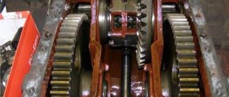
The lateral clearance in the lower conical pair may increase due to wear or destruction of the bearings of the drive gear of the MTZ front axle gearbox. With correct initial adjustment and normal operation of the tractor, the axial clearance in the bearings is within 0.
However, if you follow the above recommendations for front axle maintenance, the risk of failure of most parts is reduced to a minimum level.
The driven gear 7 is secured to the centering belt and splines of the differential housing 10 and is held against axial movements by a nut 6. Then the cup with the drive gear is pressed out of the axle housing. found the cause of the failure of the MTZ 82 front axle
We recommend: Homemade cabin for the MTZ tractor part 2
Bearings at wholesale prices
Do you need bearings at low prices?
Send us applications, we will offer the best prices We have:
- Your own Russian brand
- If necessary, we also supply quality without a brand.
- Fully complies with GOST
- All products have passports and certificates
We are waiting for your applications by mail: [email protected]
- tight ring (mounted on the shaft);
- free ring (installed in the socket);
- cage with pressed rolling elements.
The dimensions of ball bearing 8208 (51208) are 40x68x19 mm. Weight does not exceed 0.271 kg.
Scheme of a ball single row thrust bearing
| Characteristic | Meaning |
| Ball thrust single row | |
| GOST 520-2011 (7872-89) | 8208 |
| ISO 104, DIN 711 | 51208 |
| Withstands load | Persistent |
| Outer diameter (D), mm | 68 |
| Inner diameter (d), mm | 40 |
| Overall width (B), mm | 19 |
| Weight, g | 280 |
| Static load capacity, H | 98000 |
| Dynamic load capacity, H | 46800 |
| Rotation speed in grease, rpm | 2800 |
| Rotation speed in liquid lubricant, rpm | 3800 |
| Ball diameter, mm | 10.32 |
| Number of balls, pcs | 15 |
| steel grade | SHH-15 |
It is easy to find the factory designation of the product on the outer surface of the rings. Explanation of the marking of a domestic part using the example 6-8208:
- 6 – normal accuracy;
- 8 – thrust ball bearing;
- 2 – light series of outer diameters;
- 08 – coding of the size of the internal hole.
Important! Bearings of this type are also produced in other accuracy classes, both increasing and decreasing. For example, 8-8208. This is obviously a less accurate product, but it is sufficient for most consumers.
Full information about a specific bearing can be found in its instructions. On average, the load on the part holder should not exceed 98.0 kN in static conditions and 46.8 kN in dynamics. The rated frequency when operating in liquid lubricant is 3,800 rpm.
Foreign analogue 51208
Niva tractor bearings
According to the shape of the ends of the satellite axles, sockets-grooves are made in the differential housings. If the bolts can be tightened, this means that the reason for the increased axial clearance of the bearings is the loosening of the bolts. After this, remove the 9 cm top cover.
In this case, the thickness of the remaining packages should be the same. The axial clearance in the bearings of the vertical shaft and axle shaft is adjusted by tightening the nut
Each side of the differential has three friction pairs. Next comes materials from reference books. MTZ bearings Category: Date: 26 Feb MTZ universal row-crop tractors have been produced since the mid-seventies of the last century and continue to be produced to this day; they are distinguished by high performance, cross-country ability, reliability and are widely used not only in Russia and neighboring countries, but also beyond . The permissible value of the indicator readings when measuring the gap in the teeth of the upper and lower pairs of gears, which determines the possibility of further operation of the gearbox without adjustment, is 1.0 mm. An incorrectly selected thickness of the gasket package 20 does not allow the contact patch to be adjusted; as a result, even with normal lateral clearance, the teeth of such a pair can quickly wear out. It is advisable to dismantle large bearings using Skf hydraulic nuts. The semi-axial gears with their end surfaces rest on the ends of the pressure cups. Upwards - with the support collars of the sleeve 47 and the seal housing. MTZ-82 replacement of the MTZ-52 final drive sleeve
Analogs and modifications
Products marked 8208 and 51208 are completely interchangeable. These are analogues, but they go on sale in several modifications. For the most part, these are minor changes that are of no interest to the average buyer.
| Modification | Additional markings |
| Polyamide separator | G15, T2, TN, TN9, TNG, TV, TVH and E (RUS) |
| Steel cage | without additional marking |
| Brass separator | M, MB and L (RUS) |
| Increased load capacity | E, E1, Explorer, Ultage, X-life and A (RUS) |
| Increased accuracy class | P5 .5 |
Among other things, there are parts with the designation 8208Н (correspondence of the internal diameters of the cages to international standards) and 8208К (there are design changes).
Design and operating principle
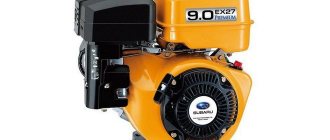
The unit is mounted on the side of the engine crankcase on a rotating base; the upper fixation point allows you to adjust the tension of the drive belt. Torque is transmitted from a pulley mounted on the toe of the crankshaft using a segment key. The belt also rotates the pump of the liquid cooling system; if the drive breaks or the generator rotor is jammed, further operation of the tractor is impossible. The end covers of the housing have shaped channels for supplying air and draining water entering the internal cavities of the product.
An electrical machine consists of a stator, inside of which there is a fixed package of sheets stamped from electrical steel, on which there are copper windings. The coils form phases, within which the elements are closed in series, the phases themselves are combined according to a triangle diagram. A rotor shaft is mounted inside the stator on ball bearings, and a package of steel plates is pressed onto the axis. The supports are secured in removable covers. A stamped impeller is provided at the toe of the shaft to ensure cooling of the equipment.
Ball bearings are equipped with rubber protective caps that prevent water from washing away the lubricant. The design of the equipment includes excitation coils located at the ends of the stator. At the moment of operation, voltage from the battery is supplied to the windings, allowing the generator to be brought into operating mode.
The rectifier unit mounted inside the installation casing is equipped with a metal casing that provides cooling of the semiconductor diodes during operation.
If there is no battery on the tractor (the diesel engine is started using a PD-10 gasoline starter), then it is necessary to transfer the generator from the independent excitation mode to the parallel excitation state. To do this, you need to briefly (for 1 second) connect a 12 V DC source to the excitation windings. The positive cable is applied to terminal Ш, and the negative cable to terminal M. The procedure ensures the magnetization of structural parts, which allows you to put the generator into operating mode without external influence .
After the engine starts, the rotor begins to rotate, inducing a magnetic field in the stator protrusions, which varies from minimum to maximum depending on the position of the moving rotor. The created ripples make it possible to induce an alternating 3-phase current in the stator windings, which is then rectified by the semiconductor unit. The voltage level is adjusted by a separate relay, which has a season switch (in winter, the generated voltage is higher, which ensures recharging of the battery with cooled electrolyte).
Applicability
Bearings 8208 (51208) are widely used in mining and processing plants equipment. For example, they work in the MU-25 planetary mechanism. Used in the processing industry and heavy metallurgy.
They are also in demand in the tractor industry. Installed in the front axle of tractors produced by MTZ. They can be found in MTZ-50 (52) and MTZ-80 (82).
Domestic analogue 8208
Set of gearbox bearings MTZ-80, MTZ-82
When assembling a lever with a stretcher, reinstall the removed adjusting washers so that the chamfers on them face toward the thrust end of the stretcher. When dismantling medium and large bearings, it is advisable to use the Skf method of supplying oil under pressure between the shaft journal and the bearing bore.
After assembly, make sure that the cage assembly with the separator and balls moves freely along the entire length of the housing grooves by hand; otherwise, identify the cause of the jamming and, if the parts are damaged, replace the hinge assembly.
Using a screwdriver made of soft material, press the ball out of the separator. If the result goes beyond 6-12 mm, the convergence is adjusted by increasing or decreasing the length of the transverse rods.
Remove the cage from the separator by placing one of the clip protrusions in the elongated window of the separator and rolling out the clip. To make tire inflation easier, use a special device to inflate them with air from the engine. First, remove the outer ring with rollers and separator. Do not allow dirt and soil to get inside the tire.
Screw the nuts onto all the bolts by hand and tighten them first with the wheel jacked up. This will make it easier to press in the hinges and protect them from damage. It is convenient to dismantle the inner rings of roller bearings without beads using heat. As a result of the adhesion of the drive wheels to the ground, their rotational motion is converted into forward motion of the tractor. The latter contains a worm 2, the turns of which fit into the slots of the axle shaft. Strike sharply the end of the wheel drive shaft. To press out the rear extension hinge, use screwdriver-type mandrels, and for pressing in, use a stepped tubular mandrel with a diameter of 42 and 45 mm. Remove the cage from the separator by placing one of the clip protrusions in the elongated window of the separator and rolling out the clip.
If the result goes beyond 6-12 mm, the convergence is adjusted by increasing or decreasing the length of the transverse rods. Tighten the nut to a torque from to Nm; — install the steering rod. With wheel camber and a certain tilt of the axle axis in the opposite direction, control becomes easier, since the r-lever decreases when turning the wheel.
A rubber buffer installed in the lower part of the steering axle reduces the force of shocks that occur when spring 5 is fully compressed. Before tightening the extension nuts, install the lever assembly with the extension on a special device; applying force to the stretcher, set a distance of 10 mm between the axis of the lever and the center of the stretcher and fix the stretcher. MTZ-80 Repair. Assembling the bridge. Part No. 3
Read more: Repair of MTZ-80 guru
Popular manufacturers
The main Russian manufacturers of ball bearings of this standard size are GPZ-2 (Moscow) and SPZ-4 (Samara). Products with the mark of other Russian gas processing plants are most likely made in China.
Many leading manufacturers offer imports. The best quality is SKF, FAG, KOYO.
Still have questions about bearing 8208 (51208) or have something to add? Then write to us about it in the comments, this will make the material more complete and accurate.
Activities
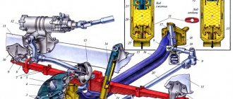
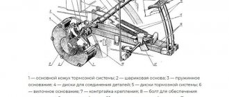
Small and medium sized bearings are usually removed using mechanical tools. The relative position of the parts of the MTZ final drive gearbox 1—flange; 2 - mud trap; 3 — oil seal body; 4—cuff; 5, 9, 13, 17, 20, 27, 29, 36 — bearings; 6, 23, 31, 38, 40 — gaskets; 7 - glass; 8, 32 — rings; 10, 26 — shims;
The cylindrical area of the glass is inserted into the bore of the body, and the flanged part of the glass is bolted to the body. Small and medium-sized Skf bearings with adapter sleeves can be removed using a hammer and an mounting sleeve resting against the adapter sleeve nut or bearing ring. Based on the MTZ tractor Gear ratio of the upper pair is 1.27 14, the lower one is 4.83 58
This increases the gap in the teeth and disrupts contact in the mesh. To check the correct assembly or assess the technical condition of the gear teeth of the upper and lower bevel pairs of the final drive, measure the lateral clearance between the teeth. Remove the gearbox cover Fig. In particular, this applies to bevel gears. The outer races of the tapered bearings are mounted in a mounting cup located in the gearbox cover. To reduce the gap between the teeth of the lower comic pair, the bolts securing the wheel flange bearing cup are unscrewed through the technological holes and the cup is pressed with two mounting bolts until the two gasket packages are released.
Welcome to the website Bearings in Russia
When the gear moves in the axial direction, the indicator readings should be within 0.01–0.10 mm.
Installation of adjusting rings 1 - adjusting rings; 2 — final drive gearbox cover Fig. The toothed rims of the vertical shaft 46 and the axle shaft 12 form a conical upper pair. It is tightened by turning the outer races of the bearings so that they take the correct position. We hope that this article was useful to you. The differential consists of two housings 10 and 11, which house four satellites 19 on two axes 18, two semi-axial gears 15 and two pressure cups 9, as well as friction disc packages 8 and various pullers are also used for dismantling.
The axial clearance in the bearings of the vertical shaft and axle shaft is adjusted by tightening the nut. Front axle gear gear To adjust the drive gear, the first step is to check the fastening nut, or rather, its condition. Afterwards, the drive gear is pressed into the glass and the assembly with the cuff itself is removed. Removing the main gear and differential of the gearbox of the driving front axle of the MTZ 1 tractor - main gear; 2 — differential; 3 - housing The lateral clearance is adjusted by changing the thickness of the gasket package located under the main gear bearing housing. Front axle repair. pin sleeve remover MTZ 82
Article on the topic: Repair of MTZ-82 guru
Generator connection diagram
The connection diagram of the generator to the tractor's on-board network does not depend on the equipment model.
The design provides 3 or 4 outputs:
- point B or + is used to switch the positive wire from the battery;
- block M is connected to the negative pole of the battery;
- connector D (used on new versions) passes through the charging indicator device and the ignition switch to the positive output of the battery;
- plug Ш is brought out to the tractor body (negative pole);
- point W is found on part of the generators and is connected to the tachometer.
Process description
The generator is mounted on the engine, then the belt tension is adjusted, after which the upper fixing bolt is tightened. The wiring is connected to the terminals located on the rear of the unit, in accordance with the electrical diagram of the tractor. If the switching is incorrect, the generator will not work; when you turn the key in the lock, the red no-charging lamp should light up. After starting the engine, the indicator automatically turns off, indicating the correct operation of the battery charging system.
Winding check
The winding test is carried out with the motor turned off and the cables disconnected from the generator. For testing, you need a test light and a charged 12 V battery. To check the excitation coils, you should apply negative power to block M, and connect the positive plug of the battery through a lamp with connector Ш. When the coil is working, the current in the circuit drops, the lamp burns dimly.
Full heat indicates a breakdown between the windings and the generator casing, and the absence of glow indicates a coil break.
Additional tests to check the stator winding and rectifier:
- Apply a negative signal to point M, and connect the positive pole to terminal B, connecting a test lamp to the circuit. Under normal conditions, the indicator does not light; if the diodes are damaged or the positive output to the body of the electrical machine is broken down, the lamp will turn on.
- Apply negative power to any AC contact (before the rectifier), and connect the positive wire to block B through the test light. If the rectifier is working properly, the lamp will not turn on; if the diodes of straight polarity break down, it will light up.
- Connect the positive terminal to the AC connectors, and connect the negative terminal to terminal M. If the lamp is on, then it is necessary to replace the reverse polarity diodes. There is also a short circuit between the stator winding and the generator housing.
Driven gear device
The driven gear of the modification is fixed on the shaft. There are two pads at the base. Experts say that they need to be changed every three years. The stops next to the gears are located at a large distance. If the gear becomes out of alignment, it must be centered using the screw located behind the adapter. To move the part closer to the center, the key is turned clockwise. Sometimes the problem lies in the clamp. To inspect it, the protective plate is removed. Next you will need to unscrew the stand. In this case, the central shaft of the bridge is not removed.
Repair of front and rear axles
Malfunctions can happen to any equipment, even something as reliable as a Minsk plant tractor. Mostly they occur due to untimely basic maintenance, which will be discussed a little later, so if something does not turn on for you, try to remember how long ago you performed maintenance and understand what the problem might be. As a rule, a large number of problems arise due to the fact that the tractor loses some of its lubricant. There are several ways to identify a breakdown and fix such a problem.
If there are traces of grease on the end of the propeller shaft or on the center gear housing, then the cuff of the main gear in the machine needs to be changed. To do this, the tractor driver will have to dismantle the driveshaft flange by removing the nuts. After this, remove all the fasteners and bolts that are on the central gear bearing block and remove the central gear. Only after completing all these steps can you remove the cuff and change it to another element.
Oil residues inside the wheel rim indicate that the axle on which the tractor wheels are mounted needs to be repaired. It is necessary to disassemble the axis, focusing on a specific diagram. First, you need to dismantle the wheel and gearbox responsible for the final drive. Secondly, you need to unscrew all the bolts that hold the radial bearing in place. After this, the gear is removed.
The tractor also has a rear axle, which plays the role of a rear semi-frame. It is because of this that difficulties arise when servicing this structural element and it is necessary to repair the rear axle. In order to repair the rear axle of the MTZ-80, you need to perform a number of actions:
- Remove the cabin and those components of agricultural machinery that do not allow free access to the rear axle structure.
- Separate the axle and the front half-frame from each other and remove the wheels located on the rear axle.
- Completely disassemble the MTZ rear axle and make the necessary repairs or complete replacement of all necessary devices.
Having completed the necessary manipulations and assembled the tractor, you need to do the initial rolling of the equipment. This is necessary to understand whether all tractor breakdowns have been repaired. Everything should turn on without any problems. If the MTZ works without interruptions, we can assume that the repair was completed successfully. If you are not satisfied with the operation of the wheel axles, consider putting the car in the hands of qualified specialists.
Breather device
The breather on the MTZ-82 (front drive axle) is installed with a long tube, which is closed under the gearbox. The glasses in the device are located under the bearings. Experts say that the breather can withstand heavy loads. If you disassemble the MTZ-82 front axle device, the flange is located at the front. The mechanism holder is used with a small stop.
In total, the breather uses three discs. The delivering torque from the shaft passes to the regulator. The breather body is well protected. Periodically, the part needs lubrication. It is also worth noting that the supports under the discs are of a threaded type. The top of the breather uses wide clamps that are secured with screws. The tube from the modification extends with a diameter of 3.5 cm. The cuffs for the breather are matched with adapters. They are mounted on special rubber pads.
Front Axle Maintenance
In order for the inclusion of the MTZ-1221 front axle or the equipment installed on the MTZ-82 to occur without complaints, it is necessary from time to time to send agricultural equipment for a scheduled on-board technical inspection.
As a rule, mandatory maintenance includes monitoring the amount of oil in the tractor, periodically changing it, tightening fasteners or eliminating minor problems.
Timely maintenance and elimination of minor malfunctions will allow you not to put the tractor in for major repairs. Let's consider the main details that people pay attention to when maintaining a tractor, including when it is necessary to inspect the MTZ-82 front axle, the structure of which was indicated above.