Dismantling a partially synchronized gearbox
Disassemble in the following order:
Remove the side cover with the switching mechanism.
Remove the input shaft bearing cover
Turn the input shaft with the cutout towards the intermediate shaft drive gear and remove the input shaft with the rollers and the synchronizer blocking ring.
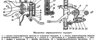
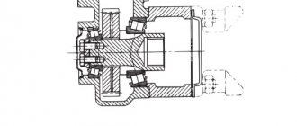
Unscrew the locking screw of the reverse gear block axle and press the axle back, removing the reverse gear block (Fig. 4).
Remove the plates securing the rear output shaft bearing.
Remove the synchronizer hub retaining ring (Fig. 5) and remove the secondary shaft back. In this case, all gears will be removed from the shaft, but the bearing will remain on the shaft.
Using a special wrench, unscrew the cover of the front bearing of the intermediate shaft.
Using a special wrench, unscrew the nut of the front bearing of the intermediate shaft and remove the intermediate shaft together with the bearing back (Fig. 6). In this case, the drive gears of the 2nd and 3rd gears will be removed from the shaft.
Using a special wrench, unscrew the input shaft bearing mounting nut, which has a left-hand thread.
Remove the bearing from the input shaft using a puller (Fig. 7).
Remove the rear intermediate shaft bearing using a puller. The bearing mounting bolt has a left-hand thread and is secured with a disc spring.
Disassembling a synchronized gearbox
Disassemble in the following order:
Remove the side cover with the switching mechanism.
Using the M8 threaded hole in the rear end of the reverse idler gear axle, press the axle back and remove the gear.
Remove the input shaft bearing cap.
Remove the front intermediate shaft bearing cover.
Unscrew the rear intermediate shaft bearing mounting bolt (the bolt has a left-hand thread) and remove the bolt's disc spring.
Using a puller, remove the rear bearings of the primary and secondary shafts by their retaining rings.
Remove the rear intermediate shaft bearing retaining ring.
Install the box so that the intermediate shaft is at the top, move the intermediate shaft forward until the intermediate shaft gear block stops in the crankcase.
Move the intermediate shaft along with the rear bearing back until the inner race of the front bearing comes out of the rollers and the rear bearing comes out of the crankcase.
Remove the rear intermediate shaft bearing using a puller.
Install the gearbox with the hatch under the shift mechanism facing up.
Remove the input shaft, 4th gear locking ring, secondary shaft assembly (supporting the 1st gear spacer ring) and intermediate shaft assembly from the transmission housing.
Disassembling the secondary shaft
Remove the thrust washer and 1st gear with needle bearing.
Remove the synchronizer hub retaining rings using a puller and the thrust washer.
Remove the synchronizer for 1st and 2nd gears together with the 2nd gear gear.
Remove the retaining ring, key and 2nd gear bearing.
Remove the 3rd and 4th gear synchronizer together with the 3rd gear gear.
Remove the circlip, key, spacer and 3rd gear bearing.
Transmission feature
On the UAZ 469, the gearbox is mechanical, designed for 4 stages. At the same time, the 4-speed gearbox is equipped with synchronizers. They are necessary for speed equalization. There are shafts, with the primary shaft based on two supports. The intermediate shaft drive gears are helical. To absorb the occurrence of radial and axial loads during movement, the rear shaft support includes a double-row angular contact ball bearing. This gearbox allows the vehicle to move in reverse. The vehicle is equipped with a transfer case. The UAZ 469 transfer case includes drive axle shafts and gears, which have a long service life.
The advantage of a manual transmission is that it is designed to last a long time. A car that has off-road qualities and is equipped with a manual transmission is excellent for use on rough terrain.
Carrying out diagnostics of the UAZ 469 gearbox
The car is subject to diagnostics if its handling has deteriorated. At the same time, squeaking noises may be heard when changing gears. Also, it is necessary to check the condition of the box if the gears activate spontaneously. In some cases, it is necessary to replace bearings and gears to solve the noise problem. If gear shifting is difficult, the synchronizers are checked. The main reason why there is a need to replace the components of the box on an SUV is their natural wear and tear.
One of the signs that the transfer case should be checked is if the grip of the wheels on the road has deteriorated, and noise from its side has begun to increase. Improper use of the vehicle leads to repair of the gearbox on the UAZ 469. In particular, it is necessary to timely change the transmission oil.
Another problem that a UAZ driver may encounter is an oil leak from the gearbox. This manifestation is the result of an increased oil level in the gearbox. Also, if water gets into the system while filling the box with new fuel, the motorist will soon face the problem of fluid leaking from the gearbox. However, it is not only the use of low-quality oil that can cause leakage, since there may be a crack in the crankcase or in the UAZ 469 gearbox cover.
Thus, the high-speed gearbox of the UAZ 469 car includes many working units that ensure optimal functioning of the automotive system. Taking this into account, the owner of the vehicle must subject the car to regular maintenance. This will reduce the risk of premature repair of the UAZ 469 gearbox.
Malfunctions and repairs
The first signs indicating a malfunction of the automotive system should force the car owner to carry out diagnostics. In some cases, this can be done on your own. Simple breakdowns can be repaired with your own hands. It is better to entrust more complex faults to a service center.
Signs indicating the need to repair the UAZ gearbox:
- deterioration of management;
- squeaks and extraneous noises when changing speeds;
- independent activation of transmission.
In most cases, when uncharacteristic noise is observed, the cause lies in wear or defect of the bearings and gears. Stiff gear shifting indicates a malfunction of the synchronizers.
The main reason for the problems that arise is the natural wear and tear of parts.
The need to check the transfer case is indicated by deterioration in wheel adhesion to the road surface and increased noise levels from the area where the unit is located. Damage is caused by: careless operation of vehicles, untimely maintenance, use of low-quality consumables, fuel and gear oil, lack of control over the volume of working fluids.
Another group of problems is related to the leakage of the oil mixture from the gearbox. Possible reasons:
- exceeding the maximum oil volume in the box;
- water entering the system when refueling;
- a crack on the unit cover or on the crankcase.
The UAZ high-speed gearbox consists of a large number of working elements and components. Their normal functioning and interaction ensure reliable use of vehicles. Gearbox repairs will not be required if you regularly inspect your vehicle.
Mechanism adjustment
After assembling and installing the new switching mechanism, it is necessary to adjust the rods and the entire system. The goal is achieved by changing the length of the vertical and horizontal rods. Do-it-yourself setup sequence:
- Move the gear shift lever to the neutral position, and move the element responsible for selecting the gear all the way.
- Move lever 1 to positions corresponding to speeds 1 and 2. While checking that the elements are not pulled up, connect and secure the selection rod.
- Similar actions must be carried out for other gear stages.
After work, you should check that the gears are fully engaged by starting first gear and reverse. The lever must not come into contact with other parts or controls. The optimal gap size is up to 3 mm.
How to disassemble
Before repairing a 5- or 4-speed gearbox (new model), you must carefully study the device diagram, prepare material and tools. To dismantle the unit yourself you will need:
- wrenches: open-end and socket;
- screwdrivers;
- hammer;
- assembly shovel.
The large weight of the product due to contact with the dispensing system requires an assistant during operation and removal of the box.
Disassembling the gearbox occurs in the following sequence:
- Fixing the machine above the inspection hole.
- Removing transmission oil to reduce unit weight.
- Removing the seats in the cabin.
- Dismantling the speed release fork, clutch pan near the muffler, frame, speedometer shaft and cardan.
- Disconnecting the dispensing system from the main structure, securing it to the side with a rope.
- Removing fasteners.
After this, you can remove the body from the car. The next step is to disassemble the gearbox stages, check all elements of the mechanism for wear, and replace non-functional parts with new ones.
How to assemble
Assembly and installation of the automatic transmission is carried out in the following order:
- Placing the box in place, tightening the bolts and other fasteners.
- Attachment to the main structure of the transfer case.
- Installation of the speed release fork, clutch pan near the muffler, frame, speedometer shaft and cardan. At this stage you can assemble the lever.
- Installation of seats in the interior.
- Filling the container with new transmission oil.
After this, you can remove the car from the inspection hole. To install a new gearbox on a UAZ and replace other parts, first carefully read the mechanism diagram.
Replacing the transfer case
When installing new components, you should use only high-quality parts that are suitable for the vehicle model. This is the key to a comfortable ride and reliable functioning of all elements of the system.
Replacing the transfer case is complicated by its connection to the gearbox, which increases the weight of the structure.
The process includes the following steps:
- Removal and disassembly of the unit.
- Fault diagnosis.
- Replacement of worn elements or installation of a new transfer case.
To dismantle the device you will need:
- secure the vehicle in the inspection hole;
- lower the parking brake lever;
- move the remaining elements for selecting and changing speeds to the neutral position;
- remove the casing, handles, all connecting wire elements, covers and lining.
The new unit must be installed in the reverse order.
Timely maintenance, diagnostics of main and auxiliary components, regular replacement of worn parts, use of high-quality fuel and oil mixtures, consumables, careful operation of vehicles and following the manufacturer’s recommendations will help to extend the service life of the mechanism.
Using special pliers or a screwdriver, remove the retaining ring from the secondary shaft.
Remove the spline washer.
Using a puller, we press the double-row ball bearing from the secondary shaft.
...and an oil deflector washer.
Remove the spacer bushing from the intermediate shaft (the chamfer is directed towards the gear).
We clamp the shaft in a vice by the splined part through wooden spacers.
Using pliers, remove the retaining ring from the bearing.
Using a wrench or a 27mm socket, unscrew the bolt securing the rear bearing of the intermediate shaft clockwise (thread is left-handed).
We remove the special washer.
Using a puller, placing an M12 nut under its screw if necessary, press and remove the bearing.
When disassembling and assembling the secondary shaft parts, you should be guided by Figure 1, which shows the parts in accordance with the assembly.
Figure 1. Disassembling the secondary shaft
Attention! Before disassembling the secondary shaft, parts 1-5 (Fig. 1) must be removed. Do not allow the secondary shaft to fall when pressing parts and assemblies out of it.
1. Remove the locking ring 6 as shown in the figure
2. Using tool 09432-3E000, remove clutch 8 (see Fig. 1) and hub 9 of the 3rd and 4th gear synchronizer.
3. Remove gear 17 (see Fig. 1) 3 gears and needle bearing 18.
4. Using tool 09432-3E600, remove gear 21 (see Fig. 1) 2 gears and bearing bushing 19.
Remove the locking ring 26.
5. Using tool 09432-3E 100, remove clutch 27 (see Fig. 1) and hub 28 of the 1st and 2nd gear synchronizer.
6. Remove gear 32 (see Fig. 1) of 1st gear and needle bearing 33.
7. Using tool 09432-3E200, remove the rear ball bearing 50 (see Fig. 1) of the secondary shaft, after first removing the spring retaining ring 54, the protective ring 53 and two retaining half-rings 52.
8. Using tool 09432-3E400, remove thrust washer 49 (see Fig. 1), remove bearing 48.
9. Using tool 09432-3E000, remove clutch 43 (see Fig. 1) and hub 40 of the 5th gear and reverse synchronizer, having first removed the retaining ring 44
Do-it-yourself dismantling of the speed box
What tools are needed to repair a transmission? To carry out repairs, you should acquire a complete repair kit. In particular, you will need open-end and socket wrenches, a hammer, screwdrivers, and a mounting blade.
It should be noted that the box is heavy, all due to the fact that the device communicates with the transfer case. Given this, dismantling the box should not be done alone.
How to remove the box? To begin the procedure for removing the checkpoint, you should perform the following steps:
- The UAZ stands on the inspection hole.
- The transmission oil is drained (this will lighten the weight of the box a little).
- The seats in the cabin are dismantled.
- The clutch release fork, frame, cardan, speedometer shaft, clutch pan, and muffler adjacent to the transfer case must be removed. The slide must be removed.
- The transfer case must be disconnected from the main gearbox. As a rule, the transfer case is wrapped with rope and suspended.
- All consumable parts (bolts, nuts, etc.) are unscrewed.
- Since the UAZ gearbox is fixed on fasteners, they need to be unscrewed and the box can be removed from the splines.
Transfer case, complete assembly of the gear unit and its installation
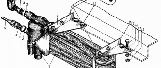
Loosen the nuts of the flanges and shafts and remove them. The handbrake must be checked for functionality and, if necessary, it must be replaced. Remove all covers and replace seals. Unscrew the speedometer linkage drive and the breather (it needs to be replaced ). Check the bearings and replace if necessary.
Reassembling the transfer case is done in the reverse order. These steps are repeated when working with other types of this car brand (including when repairing the UAZ Hunter gearbox). Install the fastening bracket to the frame. Place the transfer case on the handbrake drum and, holding it by the gear, lower it into place through the power take-off hatch.
Before this, install the lock washer from the intermediate shaft. Tighten the bolts and nuts, put on the cover with levers and check the operation of all gears. They change the release bearing, remove the levers, drag the entire assembly under the car and hang it on a rope. Place the release bearing assembly on the box and strengthen the spring. Then the input shaft and clutch are inserted. This is done as follows:
- move the box down and up;
- turn the engine by the flywheel;
- put the knot in place;
- attach pillows.
The oiler for the input shaft splines and the fork are attached in place, and the speedometer drive, cardans, handbrake, and covers are put in place. You need to return the frame cross member to its place and secure the muffler bracket to the transfer case.
The handbrake is adjusted and adjusted, and the oil is changed. If the UAZ Hunter gearbox is being repaired, you may need not only these steps, but also adjusting the rods. They screw up the hatch on the floor and install the seats. At this point, the repair of the UAZ 452 gearbox on our own is completed.
everything useful is here
Removing the gearbox
We work together on the inspection ditch.
SEQUENCE OF ACTIONS Drain the oil from the transfer case and gearbox.
We remove the transfer case and install a jack under the clutch housing. Disconnect the wire ends from the reverse light switch. We recommend removing the reverse light switch so as not to damage its terminals. Unscrew the nuts and remove the bolts of the rear supports of the power unit
Using a 12mm wrench, unscrew the four bolts securing the gearshift lever support.
Remove the lever with the spring.
Using a 10mm wrench, unscrew the four bolts securing the clutch cover cover lining.
Using a 19mm wrench, we unscrew the three nuts securing the gearbox (two on the right and the lower left), while the lower left nut rests against the gearbox housing and is not removed from the stud.
Use a jack to slightly lift the power unit (by the clutch housing).
Remove the support plate.
Using a 19mm wrench, unscrew the upper left nut securing the box.
Having moved the gearbox back, we finally unscrew the mounting nuts on the left side.
We remove the gearbox.
Install the gearbox in reverse order. Fill the gearbox and transfer case with oil
When talking about the modernization of the GAZ-69 car, one cannot help but talk about its engine. The M-20 engine, like any other engine, had advantages and disadvantages.
Its main advantage is its high-torque performance. Well, there were two main drawbacks: one of which was the engine life, which was extremely small and if the engine lasted 60 thousand km, then this was considered a good result; the second drawback was the insufficient engine power compared to its competitors.
Do-it-yourself disassembly and assembly
First you need to remove
cover of the input shaft and unscrew the left nut that is located on it (see figure). Now you need to remove its bearing. If it fails, it must be replaced. Its roller “brother” is installed inside the shaft; it also needs to be replaced. Then the retaining ring is removed from the secondary roll. Unscrew the double row bearing stopper. The shaft needs to be knocked out and the part replaced.
Next comes the third gear clutch assembly. Copper synchronizers are replaced along with crackers. Then comes the turn of the reverse gear. Unscrew the front intermediate shaft bearing box. Do not hit it with a hammer or core: it is made of silumin and may crack.
Be careful not to damage the rubber gasket because it is difficult to get out. On the removed shaft, the gears and all bearings are replaced. After this, reassemble the box in reverse order. When installing the roller on the input shaft, it is generously lubricated with Litol. All components and parts are put in place one by one so as not to make a mistake.
Engines installed on GAZ-69
Soon the UAZ-469B car went into production, and since Since the new car was much more dynamic and comfortable than previous models, most GAZ-69 owners began installing UAZ and Volgov engines in their cars.
However, among the adherents of more powerful engines, there were also those who were partial to the engine from the UAZ-450. Due to the fact that it had a piston with a diameter of 88 mm, the engine power reached 62 hp.
I somehow came across such a cylinder block, but pistons and rings for it were in real short supply at that time and I was unable to find them. I must say that the only time I accidentally saw such a rare engine assembled in scrap metal. After such a meeting, I became a little interested in restorers of old equipment, because they find exclusive parts somewhere.
There was another engine in the USSR that was chased by Kozlikov lovers and which was valued much higher among foresters and hunters than the Volgovsky. It was a Polish engine from a Nysa car.
In its pedigree, this engine had roots from the GAZ M-20 engine, but was modernized by the Poles while maintaining the old dimension and converted into an overhead valve. With an engine power of 70 hp, it pulled like crazy at the bottom and when driving tight, it had absolutely no competitors.
Based on the above, the real contender for me for installation on the GAZ-69 car was the Volgovsky engine from the GAZ-21. However, preparations for the operation to install another engine took time and in my case took a lot of time.
Around the same time, I came across an interesting article about the modernization of production processes and it concluded that it makes no sense to separately reconstruct one workshop in production, because this will not lead to an increase in output throughout the enterprise.
UAZ 469. Gearbox repair. Part 2. Assembly
UAZ gearbox assembly sequence
. Support the project Automedicine Group.
On February 18, 1974, a million UAZ-452 arrived from the assembly line (in the back of the van), which by that time had gained great popularity among motorists.
On February 16, 1976, he was awarded the Ulyanovsk Automobile Plant with the second Order of the Red Banner of Labor. On December 27 of the same year, the State Quality Mark was awarded to the UMZ-451M automobile engine, and in November 1977. UAZ-452 van.
In 1983, a group of UAZ designers received government awards for inventing the floating Jaguar car. This model was intended for the army, in particular for border guards. There are still no analogues of this car in the world: its speed on water is 8-10 km/h.
In 1992, after the collapse of the USSR, UAZ was transformed into Ulyanovsk Automobile OJSC. And already in 1993, the plant began producing cars of a new modification, UAZ-31514. This modification of the UAZ-469 car with improved consumer qualities was distinguished by the presence of a metal roof, adjustable seats, and new door locks. The expansion of a number of modifications included the completion of the UAZ-31514 with new, more economical engines and a spring-loaded front suspension.
In October 1994, the plant received the international Golden Globe Award for its outstanding contribution to the development of its economy and integration into the world economy, as well as for its competitive and high-quality products. In 1996, the company received the European Golden Mercury award based on sales volumes.
In 1997, the UAZ-3160 was awarded a Small Gold Medal and a diploma in Yekaterinburg at the International Exhibition "Europe-Asia-Transit". At the same time, the plant began production of small production vehicles (PAM). Repair of own HIP kits. The first model developed here was the UAZ-3153, which differed from the UAZ-31514 in its extended base. On August 5 of the same year, the first experimental batch of new UAZ-3160 vehicles rolled off the assembly line. This car became the basis for the development of the Simbir and UAZ-3163 cars.
In June 1998, UAZ began assembling vehicles with the UAZ-31604 diesel engine. The plant's plans include the appearance of a number of vehicles based on a new truck chassis, which includes a modern bus, a new truck and a new version of an agricultural vehicle.
Tuning the GAZ M-20 engine
When I returned from the army, I tried to boost the original GAZ-69 engine and to do this I milled the cylinder head so that the valves did not rest against it.
I also pressed out the exhaust valve guides and sharpened them to accommodate the thicker valve stem from the PAZ engine. Next, I drilled the sockets and ground the valves.
They installed PAZ exhaust valves because they had a sodium filler and did not burn even with 76 gasoline. However, the problem was that finding them was extremely difficult.
After carrying out the work described above, the valves stopped burning, and the engine noticeably increased in traction and on a straight road could accelerate the car to 110 km/h. My tuned engine lasted about 15 thousand km, after which water started to flow into the sump.
An autopsy showed that the engine block from the exhaust valve to the cylinder liner had burst and could no longer be repaired. Unfortunately I no longer remember the cylinder number. This experiment forever discouraged me from boosting engines.
True, I once put a triple shaft into a cheap engine, but there were special factory connecting rods and this Zhiguli engine ran without any complaints.
Selection of spare parts
In general, I decided to abandon boosting the GAZ M-20 engine and install the Volga GAZ-21 engine on my GAZ-69. Slowly, I found a 4-speed gearbox from a UAZ, and then a transfer case from a Bukhanka. I couldn’t find the plate from the UAZ-469B, which is placed between the gearbox and the steering wheel. However, I came across the same one from Bukhanka, but it was a little narrower than the UAZ one.
Also, I found four engine mounting mounts from UAZ or GAZ-51, because... they were practically the same. I took four spare sheet metal plates and adjusted the large holes of the engine mounts to them. In a word, I assembled everything and just waited for some unit to fail.
Conversion of GAZ-69
After some time, a breakdown occurred and I did not patch Trishkin’s caftan, but pulled out the engine, gearbox and transfer case at once.
I started the re-equipment with the installation of a Volgov engine. I secured it with the rear part to the engine cross member, and welded brackets to the frame under the front part using pre-prepared plates.
In order to dock the gearbox with the RK, I had to unscrew the body and raise it by 200 mm.
Having secured the gearbox with the transfer case, I began to manufacture the rear brackets for the transfer case support, and when I secured the transfer case, I removed the rear engine mounts from the yoke.
The time had come to cut out in the body what was preventing it from being put in place, so that in the future, to remove the gearbox and gearbox, you wouldn’t have to remove it again.
When the body was installed, the intermediate axis of the clutch drive had to be shortened and welded again, because it was impossible to put it in place, because it did not fit between the frame and the flywheel housing.
Next, it was the turn of the driveshaft. I couldn’t find the original rear universal joint, so I had to solve the problem using a makeshift method. I took two cardan shafts with the condition that one of them had a normal working splined part. I measured the distance between the flanges of the bridge and the transfer case, and then cut them with this calculation, as it turned out, almost in half.
Then, he took two corners of the thirty and clamped these remains of the cardans with the corners in a vice. The corners acted as centers for me. Then, he placed two electrodes on the cardan forks and aligned the cardan shafts so that they were in the same plane.