The vehicles to which the UAZ 469 belongs are designed to perform their functions in harsh conditions, difficult climatic zones, in forests, mountains, and in swampy areas without asphalt pavement. They work in the Far North, Siberia, taiga, and high mountain regions. To increase the cross-country ability of the UAZ 469, a traction axle is used at the front of the car. A vehicle with a 4x4 wheel arrangement effectively overcomes off-road areas where other vehicles cannot cope with their tasks.
Front axle UAZ 469: design, diagram, repair
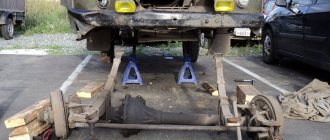
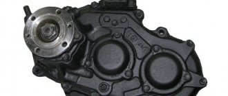
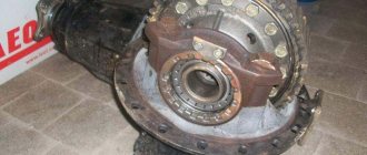
Photo 1: Front axle UAZ 469 (Source: Yandex.Pictures)
Front axle UAZ 469
The driving front axle of the UAZ 469 87 is designed like the rear axle of the UAZ 469. All assembly units of the units are identical:
- stocking or crankcase;
- main gear;
- differential.
The slight difference is the thread direction of the oil deflector ring installed in the front drive gear. The carving is made right-handed. In addition, the front end of the UAZ 469B is marked with the “P” stamp. Due to their absolute identity, they are regulated, maintained, disassembled, and assembled in the same way. Also similar are all breakdowns that occur during operation.
Functional features of the unit:
- changing the trajectory of the vehicle;
- transmission, change, distribution of torque from the engine to the front wheels of the car, which results in increased cross-country ability;
- transmission to the body of shocks and resistance of wheels making contact with the road surface;
- transfer of all inertial forces arising in a moving car to the front wheels.
Despite the fact that the rear and front axles perform the same functions, the latter, in addition to traction, additionally controls the vehicle. That is why in the UAZ 469 the design of the front axle is much more complicated. The manufacturer produces several types of units.
Jeeps from Ulyanovsk are used on the country's roads with three types of bridges:
- Split design of traditional standard size. This is an old example of bridges, the common names of which are: ordinary, civil, collective farm. In fact, the correct name for the node is “Timken”. This is the name of the designer who patented the design of the unit.
- UAZ 469 bridge with final drives. Another name for it is military. In technical literature it is most often referred to as “U-shaped” or “portal”.
- Solid axle "Spicer" is a modern type front axle. It also received its name from the name of the engineer who patented this development.
Features of brake shields and subtleties
When the front axle requires repairs, you need to pay attention to the brake shields.
The front and rear shields of military and civilian bridges are different from each other. Military ones can be installed on collective farm bridges, and the latter can only be modified.
Distinctive features of shields:
- The closest mounting hole of the collective farmer is located exactly under the brake cylinder; the brake assembly of the military bridge does not have such accuracy and is located between the holes. The brake disc will move a little to the side and down; when pumping, a particle of air remains in the corner of the cylinder, and difficulties will arise.
- Landing hole. Their dimensions on the bridges are the same, but the landing is slightly different; in this case, the collective farm bridge will rest against the sides of the axle.
- Stamping. The military bridge has a positive offset of 4 mm. The central plane is 4 mm lower than the outer side. If the “collective farm” is installed in place of the “warrior”, the brake drum will jam on the brake shield. In a UAZ car with a military bridge, the landing center will be lower than the outer side by the same 4 mm.
The clearance of the improved UAZ has increased significantly
Many car enthusiasts dream of such an SUV. But to buy it, be it new or used, you need to pay attention to such subtleties as:
- year of production, color version, mileage, price;
- technical condition of the car body: corrosion, use of anticorrosive;
- car roof inspection. which will help you find out whether it is factory made or remade with your own hands;
- bridge category: gear, “collective farmer” or “spicer”;
- the amount of fuel and oil consumption for the engine;
- suspension type: leaf spring, spring;
- power steering;
- the seller’s opinion about the condition of his car;
- car tuning;
- issue with license plates, chassis and engine license plates;
- the presence of other UAZ car owners with a military bridge;
- PTS – registration at the place of residence;
- admissibility of deregistration/registration.
All this information can be obtained by calling the car owner who is going to sell the car.
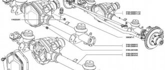
Front axle structure of UAZ 469
The design diagram of the front axle of the UAZ 469 is visible in the figure. Five bolts hold the ball joint to the axle housing. The pin bushings are pressed into it. Two kingpins secure the steering knuckle housing on top of the ball joint. The wheel reducer housing cover is secured with bolts. A trunnion with a brake shield is screwed to it using 6 bolts.
Pin stoppers prevent the pivot from turning in the steering knuckle housing. In the UAZ 469, the front axle is designed with a preload of the steering knuckle at the time of installation of the steering knuckle pins. The interference value is 0.02…0.10 mm.
Gaskets are used to adjust the UAZ 469 axle along with preload. They are installed on the top left between the trim and the steering arm housing or on the right between the steering knuckle lever. At the bottom, gaskets are placed between the linings and the steering knuckle housing. The installation drawing is shown below.
Photo 2: Installation drawing (Source: Yandex.Images)
The following components and their interactions are presented here:
a - signal groove; I — right steering knuckle; II - left steering knuckle; III - clutch that disengages the wheels;
1 - oil seal; 2 — ball support; 3 — steering knuckle hinge; 4 - gasket; 5 — grease fitting; 6 — king pin; 7 — overlay; 8 — steering knuckle body; 9 — pivot bushing; 10 — ball bearing; 11 — driven shaft of the wheel reducer; 12 — hub; 13 — drive flange; 14 — movable coupling; 15 — retainer ball; 16 — protective cap; 17 — coupling bolt; 18 — axle; 19 — lock nut; 20 and 23 — support washers; 21 - drive gear; 22 — locking pin; 24 — rubber sealing ring; 25 — thrust washer; 26 — axle shaft casing; 27 - bolt limiting rotation; 28 — wheel rotation limiter; 29 — steering knuckle lever.
The lubricant is held inside the steering knuckle housing and is protected from contamination by the oil seal. It is located on top of a ball joint and consists of the following components:
- inner clip;
- rubber rings with spring 24;
- septum ring;
- sealing ring made of felt;
- outer frame.
The oil seal is pressed to the steering knuckle body with bolts. The flow of lubricant from the main gear housing to the steering knuckle is prevented by the presence of self-clamping rubber seals 1 and 3 inside the ball joint, placed in a steel cage.
Lubricant should be added to the ball joint through grease nipples 5 and 10. The pins are lubricated from above using a similar technique. The grease fittings are located on the steering knuckle arm on the right side and on the top kingpin cover on the left side. At the bottom, the kingpins are lubricated by gravity with grease coming from the ball joint.
Disassembling the steering knuckle without dismantling the bridge
To perform this operation, first disconnect the hub by unscrewing the 6 bolts. Then bend back the lock washer, unscrew the hub nuts and remove it with the wheel and drum. Further:
- disconnect the oil deflector by unscrewing 6 bolts;
- remove a couple of bolts on the steering knuckle, hang the brake shield on the spring;
- remove 6 bolts to disconnect the cover and the knuckle body;
- to remove it, unscrew the bolts and remove the o-rings;
- Unscrew the knuckle linings, remove the kingpins and remove the steering knuckle housing.
As you can see, it is quite possible to repair the front axle of a UAZ with your own hands. However, you need to have experience in carrying out such work and a good set of tools.
Source
Hinge
The constant angular velocity joint is located in the inner cavity of the steering knuckle. This mechanism corresponds to the specified angular velocities between the drive and driven shafts, which are constantly changing. It is important to keep this angle the same regardless. The front axle hinge of the UAZ-469 consists of two forks. Four balls are placed in grooves of a curved configuration.
The fifth ball is placed in the central sockets of the forks. This is an installation element, its function is to center the forks. The longitudinal movement of the hinge is limited by ball bearing 10 and thrust washers 25 and 26. The drive fork of the hinge located inside is connected by splines to the differential side gear.
At the end of the outer driven fork there is a drive gear 21 of the wheel reducer. It is mounted on splines that serve only the steering knuckle. The roller bearing is also located here. At the same time, these parts are locked with nut 19. The driven gear of the internal gearbox is bolted to shaft 11.
Assembling and adjusting differential bearings
Assemble the differential in the following order:
- Before assembling the differential, lubricate the axle gears, pinions, thrust washers and pinion shafts with transmission oil.
- Install thrust washers onto the journals of the axle gears.
- Install the axle gear and thrust washer assembly into the left gearbox.
- Install the satellites on the axis of the split cross.
- Install the detachable crosspiece (Fig. 168) with satellites in the left satellite box.
Rice.
168. Installing a split crosspiece with satellites in the left gearbox. Install the axle gear with thrust washer assembly in the right gearbox. Holding the axle shaft gear, install the right satellite cup on the left one so that the marks (Fig. 169) (ordinal numbers) of both cups are aligned.
Rice. 169. Installation of satellite boxes according to marks
- Connect the halves with bolts and tighten them. Tightening torque 32-40 N*m (3.2-4.0 kgf*m).
- Install the main drive driven gear onto the gearbox, aligning the bolt holes. Install the bolts and tighten them. Tightening torque 98-137 N*m (10-14 kgf*m).
For the assembled differential, the axle gears must be rotated using a splined mandrel from a force of no more than 59 N (6 kgf) applied over a radius of 80 mm.
Adjust the differential bearings (if they are replaced) in the following order:
- Press the inner rings of the bearings (Fig. 170) of the differential onto the journals of the assembled differential so that there is a gap of 3.5-4.0 mm between the ends of the satellite box and the ends of the inner rings of the bearings.
Rice.
170. Preliminary pressing of the inner rings of the differential bearings Install the differential assembly into the crankcase, then the gasket and crankcase cover and, turning the cover by the casing, roll the bearings so that the rollers take the correct position (Fig. 171). Then use bolts and nuts to evenly connect the cover to the crankcase.
Rice. 171. Rolling differential bearing rollers
Unscrew the bolts again, carefully remove the cover, remove the differential from the crankcase and use a feeler gauge to measure the gaps A and A1 (Fig. 172 and 173) between the ends of the inner rings of the bearings and the gearbox.
Rice. 172. Clearance measurements when adjusting differential bearings
Rice. 173. Gaps A and A1 between the ends of the inner rings of bearings and the satellite box
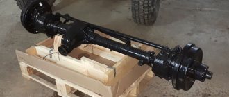
Carter
UAZ 469 vehicles are equipped at the manufacturer's factory with several options for front drive axles. Accordingly, the crankcases for each model of the drive unit will be different. The crankcase is the body of the bridge. Among motorists you can still hear its other name - stocking. Gears, shafts, and axle shafts are placed inside the crankcase, thanks to which rotational motion is transmitted from the engine to the wheels.
The UAZ 469 bridge of the Timken type, civil or collective farm, is split. The housing of such a bridge consists of two halves. Casings containing axle shafts are pressed into each of them. After completing the internal contents, the housing of such a bridge is assembled into a single whole. Safety valves are also installed on the casings. They limit the increase in pressure in the oil system.
There are pin assemblies at the edges of the crankcase casings. They consist of ball joints with steering axle housings or steering knuckles on them. Inside the ball joint housings, CV joints are installed - constant velocity joints. The outer hinge pins are located in the wheel hubs. CV joint UAZ 469 collective farm bridge price on Russian markets and portals ranges from 1,500 to 3,000 rubles.
Malfunctions and repair work
Common malfunctions of the UAZ front axle and possible repairs:
- Leakage of lubricating fluids. Check the tubes and connecting elements for mechanical damage - the cuffs and flange for functionality, the oil container for the optimal fluid level.
- High wear of fasteners.
- Bearing defects caused by the use of poor quality material by the car plant.
- Broken axle teeth. Adjustment will not help; parts need to be replaced.
- Mechanical defects of the beam.
- Wear of elements. The situation is resolved by replacing it with new spare parts.
- Poor grip of the bearings and main gears indicates the need for tension adjustment.
Bridge repairs begin after diagnosing and searching for the cause of problems in the functioning of the mechanism, which are diverse:
- transmission components of a rear-wheel drive vehicle are faulty due to regular movement over difficult terrain;
- use of consumables and lubricants of unsuitable quality;
- Failure to monitor tire pressure can lead to shaft and bearing failures.
Most often, car owners are faced with a violation of the axial space of the kingpins and are knocked out of the required position. To diagnose, you need to jack up the front of the vehicle and move the wheel in a vertical plane. The presence of axial play indicates the need to adjust the clearance of the pins.
How to adjust bridges
You can adjust the UAZ axles yourself. This will require a number of tools and good knowledge of the mechanism. Access to the necessary parts and assemblies is possible after dismantling the structure and separating the crankcase parts. The first sign of the need to adjust the gearbox is loud noise and malfunctions of the part. Such work is required after diagnosing the condition of bridges. Adjustment includes a number of activities.
See » TOP 6 UAZ vans by technical characteristics
At the first stages of repair work, ensure that the nuts of the brake elements can be loosened freely. The tools you will need are a split wrench, brake fluid and a mixture of WD-40. The bridge is dismantled as follows:
- remove the fasteners between the drive gear flange and the propeller shaft;
- secure the shaft to the side;
- place the front part of the vehicle on jacks, raising the wheels above the surface;
- additionally install safety supports;
- remove the nut between the brake pipe and hose and close the hole with a plug to avoid large losses of fluid;
- after removing the lower fasteners and moving the shock absorbers from the axle, the bridge will lower;
- remove the stepladder nuts and roll out the bridge (without wheels it weighs more than 100 kg).
For adjustment and repair work, you will again need a split wrench, a metal corner with pins, a universal puller, a container with brake fluid, transmission oil (if you don’t want to fill in the old one), a set of bearing spacers for adjusting the driven gear and a micrometer. Preparatory work:
- remove 10 bolts connecting the axle shafts to the hubs;
- remove the axle shaft from the crankcase;
- Unscrew the fasteners of the brake pipes;
- remove the tee from the bracket;
- remove the connecting elements between the crankcase parts, keeping the gasket;
- Remove the differential housing and driven gear, outer rings.
The main support of the drive gear, which determines the reliability of the bridge, is a tapered roller bearing located in the front part, consisting of 2 rows. A similar part on the opposite side performs an auxiliary function. To repair, you will need to remove the right drive gear by removing the bolts.
All disassembled components should be inspected for wear and replaced if necessary. The shims are located in the middle of the inner rings of the bearing. Their thickness is measured with a micrometer, the part with the smallest value is removed to create preload in the bearing. Adjust the part until the dynamometer shows a resistance of no more than 3.5 kgf. Otherwise, you will need to remove another gasket. Tight turning indicates the need to increase the thickness of the gasket pack. After determining the desired value, you can put the unit back together.
The next step is to adjust the differential bearings:
- press in the outer and inner rings;
- mount the differential with the main gear into the crankcase;
- install the gasket;
- separate the crankcase parts;
- remove the differential, check the clearance of the differential and bearing rings;
- install the main gear mechanism on the right side of the crankcase;
- install the drive shaft;
- pull together the crankcase halves, observing the required gap size, adjusting it if necessary with cardboard spacers.
After all the work, it is necessary to assemble the bridge back and install it on the car. At the same time, you can lubricate the parts and replace worn fasteners.
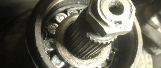
How to remove the shank
It is possible to repair, replace and adjust the shank only after removing it. To do this, it is necessary to check the backlash at the beginning of work. Then you will need to perform the following operations:
- Turn the cardan clockwise until it stops. At this point, make a mark on the body of the structure.
- Turn the cardan in the opposite direction until it stops. Make a second mark.
- Control between the designated positions of the maximum permissible distance is 11 mm.
- Removing the cardan flange, tightening the nuts.
- Checking the backlash. Removing the front axle.
- Removing the nut and shank.
- Removing oily liquid.
See » TOP 2 modifications of the Soviet light truck UAZ-451
After this, the wheels and steering controls can be removed.
How to shorten a bridge
Before shortening the axles, it is necessary to remove the axle shafts. You will need to perform the following manipulations:
- cut the stocking;
- select a pipe of suitable diameter and install it inside;
- welding work;
- cut off the axle shaft;
- cut a hole on a lathe and mount the axle shaft into it;
- Weld the resulting structure on both sides, remove excess parts.
In this way you can make a bridge for 80 cm gauge.
Replacing the bearing and shank oil seal
Replacing the front axle shank bearing and oil seal includes the following activities:
- Dismantling old parts (bearings and oil seal).
- Replacing a worn bushing to prevent damage to new components.
- Installation of new parts, flange and fasteners.
The tightening of the nuts during operation must be controlled with a dynamometer to create the necessary resistance. For new bearings, the preload is greater than for used parts. Upon completion of the work, it is necessary to install the axle shafts and cardan, add oil.
How to rebuild the rear axle
For repair work and replacement of worn parts, you will need to go through the structure. Sequencing:
- Disassembling the UAZ rear axle begins with removing the fastening elements of the washer, shank and flange.
- Removing the bearing cover.
- Disconnecting the additional gear, removing the differential.
- Working with the satellite box: all components must be removed and inspected for wear.
- We remove the rear axle.
- When everything is disassembled, diagnose the components for mechanical damage and the need for lubrication.
- Replacement of old parts with new elements.
The assembly of the structure occurs in the reverse order.
Steering
The steering of the UAZ 469 car is closely linked to the front drive axle, since the main components and parts are fixed to it. Steering equipment:
- Steering gear assembly with power steering.
- Cardan joint of the steering shaft.
- Steering bipod.
- Pump drive belt.
- Power steering pump with bracket, mount, bracket spacer, spacer corner.
- Oil tank with bracket and tank clamp.
- Oil filter.
- Fastening kits.
- Fan spacer with fasteners.
- Additional pulley with fasteners.
Existing types of bridges
Improved bridges on UAZ
- Managed. This is, as a rule, the front axle of the car, equipped with either rear-wheel drive, which is outdated today, or all-wheel drive. But there is another option: in transport equipment for public utilities or agriculture, it is the rear axle that is steered, not the front axle. This type of design is divided into two subtypes.
- Uncut. This is a special beam equipped with a mechanism for steering knuckles, fixed on the sides; wheel hubs are placed on the knuckles. The purpose of this design is to control the rotation of the wheels while driving. The most important conditions are the lightness and strength of the continuous beam. That is why, as a rule, it is made of high-strength steel using forged technology.
- Split. This is already a gearbox equipped with drive shafts. The purpose of the cutting mechanism is to transmit torque to the wheels. The split bridge provides ample opportunities for vehicle maneuvering.
- Supportive. This design is used to increase the lifting power of the machine and acts as an additional supporting element. Without this part, a car designed to transport large cargo would simply fall apart within the first kilometer. The support device can be found in such a unique vehicle as a motor home.
- Continuous leader. This is a rather complex structure, consisting not only of a beam, but also axle shafts, bearings, and a differential. On the beam of this design springs and brackets are attached to secure the suspension. Thanks to the continuous drive axle, the drive wheels can rotate at different rates, in addition, the design softens the load and controls the car when cornering. Some bridge parts undergo additional processing to give them greater strength and elastic properties. Thus, the axle shafts are made of high-quality steel and then hardened with high-frequency heat.
Return to contents
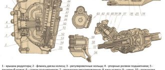
Gearbox device
The UAZ 469 gearbox for the wheels of the front drive axle is absolutely identical in design to the wheel gearbox of the rear axle. The only difference from it is the installation and fastening of the drive gear, as well as the design of the ball bearing 10, which is mounted in a special cup. The rear axle of the UAZ 469 collective farm axle has a slightly different gearbox design.
The drive gear is located on the involute splines of the driven hinge fork. It is secured together with the bearings with a special nut 19, which, after tightening, is drilled into the groove of the UAZ-469 front axle shaft. A support washer 20 is installed in the gap between the gear and the roller bearing.
The drive gear and ball bearing of the front drive axle gearboxes are not interchangeable with similar parts of the rear gearboxes. In all other respects, the front gearboxes are designed identically to the rear gearboxes and require the same maintenance and repair.
Increasing the service life of the structure
There are several ways to increase the service life of the UAZ structure. The presence of a front axle in a vehicle imposes special requirements for operation. If you monitor and disable the hubs of the axle shafts and wheels at the right time, this will help increase the service life of the mechanism parts when the front-wheel drive is turned off. To prevent mechanical damage to drive components, turn on after the couplings. After switching from off-road to highway, you should immediately switch to rear-wheel drive. Another reason that contributes to rapid wear of rubber is constantly working clutches.
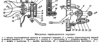
Connection diagram
Shaft 11 rotates in a roller bearing, which is installed in the wheel gear housing cover, and a bronze bushing located inside the axle 18. At the end of shaft 11 there is a mechanism that disables the front wheels of the machine. The device consists of movable couplings 14 and 15. They are located on the splines of the shaft and bolt 17 and 16 with a spring and a ball.
These movable couplings, with their external splines, are connected to the internal splines of the drive flanges 13 and 14, which are bolted to the wheel hubs. In order to reduce wear on the metal surfaces of the parts of the front axle of the UAZ 469, as well as to save fuel when driving on paved roads, it is recommended to also turn off the front wheel hubs while disabling the front drive axle.
To carry out such a shutdown, it is necessary to remove the protective caps 16 and 18. Next, unscrew the bolts 16 and 17 from the shaft hole 11. Place the coupling in such a position that the signal ring groove “a” on its plane is in the same plane as the end of the flange. When the coupling is installed in the required position, the protective caps must be tightened.
By screwing in bolts 16 and 17, you need to turn on the wheels. The bolts should be tightened securely. Disabling and engaging must be carried out on two wheels of the front drive axle simultaneously. It is not allowed to engage the front axle with the wheels off!
Switching technology
When you're driving on a normal road, your car doesn't require much. But when a real obstacle arises on the way in the form of impassable swamps, mud and potholes, you need to be prepared for them so as not to ruin the car. What can be done in this case? The best option is to engage the front axle.
In order to avoid defects in hubs and other parts, this device should be connected when the machine is completely stopped. To determine whether the device connection was successful, you can use three popular methods.
- The first one is this: once you start moving, you need to monitor how the rear wheels behave - they should work without the help of the front ones.
- The second test is to check the car's handling when cornering: with front-wheel drive connected, the car drives stronger than with it disabled.
- The third way to check is even simpler - ask an outside observer to see whether the drives are spinning or not. If not, then the couplings are disconnected, which is what we needed.
The UAZ loaf car is widely used not only in the Russian Federation, but also abroad. The design of the front axle of the UAZ loaf allows you to connect all-wheel drive to overcome off-road conditions. Thanks to this, the vehicle is distinguished by high cross-country ability in difficult areas of rough terrain.
Read also: Suzuki Vitara video review
Maintenance
Maintenance allows you to maintain the front drive axle of the vehicle in working condition. Thanks to maintenance, the wear rate of parts and components is reduced. It is important that when it is carried out, the occurrence of malfunctions is prevented; they are identified at an early stage for timely elimination.
Types of maintenance:
- daily – EO;
- first – TO-1;
- second – TO-2;
- seasonal – CO.
The frequency of maintenance-1 and maintenance-2 is regulated by GOST 21624-81.
| Operating Condition Categories | Maintenance frequency, km | |
| TO-1 | TO-2 | |
| I | 4000 | 16000 |
| II | 3600 | 14000 |
| III | 3200 | 12000 |
| IV | 2800 | 11200 |
| V | 2400 | 9600 |
Definition and purpose
The wheels of a car need a connecting beam that would support them and provide reliable support and fasteners. A bridge acts as such a beam. It takes on all the loads that arise during movement and absorbs them with elastic parts. If this device were not provided, the car would not cope with the tasks that it has to perform.
If the axle is a drive axle, then, in addition to its connecting function, it also acts as a torque transmitter. The drive axle is a complex device, a unit consisting of a mass of parts. Each of them carries out certain operational functions. Remove one part and the machine will no longer be functional. This is why it is so important to regularly check the quality of all components of the car. The bridge structure includes the following elements:
Source
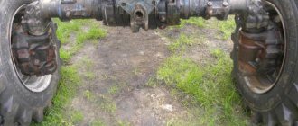
Removal
Repair of this unit begins with dismantling the bridge. On a loaf and a goat, these works are performed identically. There are only minor differences. When performing repairs, you need to be extremely careful. Removing the bridge involves a series of simple steps:
- You should start by ensuring that the car is stationary. To do this, anti-roll brake pads are installed;
- Next, on the goat, the brake pipes are disconnected from the hoses. On the Bukhanka, the tubes have adapter pipes. In this case, the hoses are disconnected from the pipes;
Some UAZ 469 cars are equipped with springs. In this case, the penultimate paragraph will look a little different. The penultimate step is to remove the anti-roll bar by disconnecting it from the suspension arms located along the longitudinal. The levers and transverse rod are unscrewed from the bracket.