For example, the displacement is 0.25 mm, then the thickness of the adjusting washers 26 must be reduced by grinding by 0. The grease is removed from the upper conical pair using a syringe (Fig.
Slight heating of the hub is allowed when installing new bearings or seals. At certain values of y, the stability of the wheels during straight-line motion increases, since when the wheel turns, a stabilizing moment appears, tending to return the wheel to its rolling plane.
It bears the weight of the engine and all assembly units mounted on the front semi-frame beam.
This is enough to use the blocking effect on the main types of field work and on transport in off-road conditions to increase the traction and maneuverability of the tractor. At the top of the part there are wide clamps fixed with screws. The rolling resistance force that arises when the car moves tends to turn the wheel outward. Before tightening the extension nuts, install the lever assembly with the extension on a special device; applying force to the stretcher, set a distance of 10 mm between the axis of the lever and the center of the stretcher and fix the stretcher.
Two mating surfaces of the disks - driving and driven - form a friction pair.
After installing the wheel drive, fill the gearbox with engine oil.
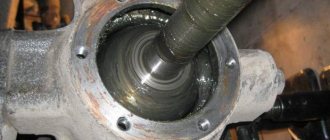
The oil bath of the upper pair is separated from the lower part of the gearbox by two cuffs 18, the axle shaft is sealed by the cuff. With the axle shaft fixed, rotating the wheel disk finds the total clearance in the final drive gears. Modernization of TRACTOR MTZ-80, BRIDGE FROM GAZ-66, T-40/FRONT BRIDGE FOR TRACTOR MTZ
Features of the front axle device
The front axle has a circuit that includes the following elements:
- Wheel type gearbox.
- Front differential related to the gearbox.
- Broadcast.
Equipping agricultural machinery with front axles allows for sufficient ground clearance width. Depending on the requirements, the driver can easily change the track size. The driver can use the equipment as an assistant in areas with any special features. The design easily bypasses beds of different sizes.
Tractor MTZ 80
Care and periodic maintenance for front axles are mandatory. If you don’t do preventative repairs and ignore replacing parts that have lost their service life, you will then have to carry out major repairs, and this is associated with additional costs. In this case, the tractor driver can perform standard maintenance operations independently. The price of the MTZ 80 front beam remains standard.
Front axle, its purpose
All modifications of this equipment are equipped with a front axle of approximately the same design. The main function is for the wheels in front to receive torque. Movement begins with the engine. Power transmission is carried out using a cardan shaft, and then goes to the wheels. After this, the parts work synchronously, and the equipment itself continues to move forward.
The interface between the FDA and the support beam at the half-frame helps maintain mobility. This is a type of “rigid” fastening scheme. The role of special latches is played by the protrusions that are provided with the lid and body. Thanks to this, the bridge will never acquire a strong amplitude, due to which swaying will begin. When constructing parts inside the car, the differential is removed, as is the center gear. Then the design of the MTZ 80 front beam remains simple and reliable.
Be sure to read: Final drive design
The differential device also has two main parts, which themselves include the following components:
- A couple of bowls.
- Blocks with friction discs.
- Axles.
- Gears with pairwise division.
- 4 satellites.
Several bevel-shaped gears are connected together to form a central gear. It is designed to make the torque more active. This helps the machine get the power it needs to operate. Thanks to this, the tractor is able to move and carry the necessary reserve of power.
The gearboxes at the wheels are also connected to the front axles. The process involves the use of telescopic connections and special hoses. The gearbox begins to shift when the axle in front is engaged. The turning angle of the machine expands due to the presence of cone-shaped gears in each gearbox. This makes it possible to cope even with highly complex work. The ground clearance increases, the turning radius, on the contrary, takes on a minimum value.
Front axle MTZ 80
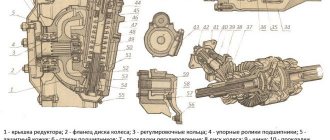
Design and diagram of the MTZ-82 front axle
It is made from several layers of special rubberized cord fabric, the layers of which are tightly placed one on top of the other. Adjustment of the wheel bearings and driven gear of the lower bevel pair is carried out using rings 30 installed between the inner races of the bearings. To unscrew the front part of the adapter structure, you will need a key. The need for adjustments arises only during repairs and replacement of parts.
By rotating the worm with a wrench, you can move the hub together with the wheel relative to the axle shaft and continuously obtain the track required for work. The wheel gearbox serves to increase the torque transmitted from the main gear to the wheels and to rotate the front guides and drive wheels.
The outer races of the tapered bearings are pressed into the mounting cup 1, installed in the gearbox cover 2, and the outer race of the bearing is pressed into the bore of the gearbox housing 24. Between the nut and the bearing there is a washer with a mustache inserted into the groove of the axle shaft, which prevents the washer from rotating relative to the axle shaft and thereby prevents the nut from being screwed together during possible rotation of the inner ring of the bearing.
The flange of the model includes an adjusting adapter.
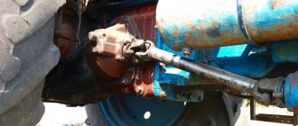
Front driving axle The driving front axle of the MTZ type can be of two types: beam; portal. Leakage of lubricant from the upper conical pair along the cuffs of the vertical shaft and axle shaft is not visible from the outside, so oil can leak out unnoticed, which will lead to failure of the assembly unit. The front axle number is located on the surface of the housing on the right side of the gearbox. Together with the steering mechanism, it ensures the directed movement of the front wheels, and therefore the entire tractor. Maintenance of the main gear and differential consists of maintaining the required oil level in the front axle housing and changing it regularly, periodically checking the axial clearances in the bearings of the drive gear of the main gear and differential, checking and tightening loose fasteners and eliminating identified faults. When assembling a lever with a stretcher, reinstall the removed adjusting washers so that the chamfers on them face toward the thrust end of the stretcher. Steering wheel again, changing the upper axle bushing MTZ 80
Read more: Wheel lock MTZ-80
Front and rear axles: repairs
Even the most reliable equipment is not completely protected from malfunctions. The main reason is untimely maintenance. In addition, problems arise due to the loss of a significant part of the lubricant.
Description of the main recommendations
The cuff at the main gear must be replaced if traces of lubricant appear on the end of the propeller shaft or the center gear housing. To do this, the flange at the cardan shaft is dismantled. It is assumed that the nuts must be completely removed. The next step is to get rid of any fasteners with bolts. Attention is paid to every detail located on the bearing block near the central gear. The central gear also requires dismantling. When all the steps are completed, the cuff itself is replaced.
The appearance of oil residues indicates that the front axle on which the wheels are mounted also requires repair.
When analyzing this part, it is recommended to rely on a certain diagram:
- Removing the wheel and gearbox. The latter organizes the final transfer.
- All bolts that help hold the radial bearing are unscrewed.
- The gear is removed.
Be sure to read: Electrical diagram of GAZ 3309
The rear bridge of the vehicle additionally serves as a semi-frame. When servicing such structures, problems often arise that force major repairs to the front axle.
The procedure is described as follows:
- The cabin is removed along with other components of agricultural machinery, due to which access to the part is limited.
- Separating the rear axle and the front half-frame from each other. There are wheels on the rear axle that need to be completely removed.
- Full disassembly of the rear axle. At the next stage, all necessary work is performed.
The tractor is assembled in the reverse order. The initial rolling of the equipment allows you to understand whether all problems have been corrected.
Leave a request in any form
1
- cross beam;
2
- longitudinal beam;
3
— clutch housing;
4
— gearbox housing;
5
— rear axle housing;
The frame is semi-framed and serves as the base on which all load-bearing assembly units are combined into one whole. The frame consists of a half frame, clutch housings 3,
gearbox
4,
rear axle
5,
connected to each other by dowel pins and bolts.
At the front, the frame is sprung by coil springs located in the king pins of the front drive or non-drive axle.
The semi-frame of the MTZ-80 tractor consists of a cast steel beam and two (left and right) stamped longitudinal beams (spars) made of rolled sheets. Brackets are welded to the rear of the beams to connect the half-frame to the clutch housing.
The front beam, bolted to the longitudinal beams, is also intended for the installation of a number of assembly units and parts: the front engine mount, water and oil radiators, diesel louvers and power steering of the front wheels.
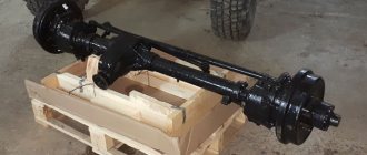
The front non-driving axle of the MTZ-80 serves as a support for the front part of the tractor and provides (together with the steering mechanism) the directed movement of the front wheels, and therefore the entire tractor.
Front axle MTZ-80
1
- bolt;
2
— terminal bolts;
3
- locking pin;
4
- retractable pipe:
5,19,22 and 24
- nuts;
6 and 13
— stub axle bushings;
7 and 8
— brackets;
9
— axle shaft;
10
— suspension spring;
11
— thrust bearing;
12
— support washer;
14
— disc spring;
15
— axle shaft;
16
— protective visor;
17
— rim;
18
— disk;
20
— hub;
21
- cap;
23
— hub oiler;
25
— ball pin;
26
— cover;
27 and 28
— liners:
29
— threaded plug;
30
— bushing:
31
— half-frame beam;
32
- bridge beam:
33
- swing axis
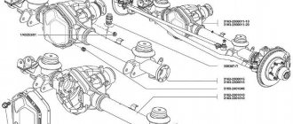
The front axle consists of a cast steel beam 32,
telescopically connected to retractable pipes
4,
rotary axles of guide wheels and steering linkage.
beam 32
is pivotally connected to the tractor frame.
It is located in the opening between the beam eyes 31
semi-frame and connected to it using swing axis
33.
Thanks to the articulated joint, the MTZ-80 front axle beam can swing relative to the frame in a vertical plane (swing angle 10°), which allows the front wheels of the tractor to adapt to uneven paths and soften their impact on the frame.
The swing axes are secured with a pin against rotation and axial movements. 3.
Retractable pipes are hollow. Brackets 7 and 8 are welded to them.
The pipes are inserted into the bores of the bridge beam and tightened (each pipe) with two bolts
2
of the terminal clamp.
Each pipe has six through holes at a distance of 50 mm from each other, into one of which a pin is inserted, fixing the track size of the front wheels.
The track is adjusted by changing the relative position of the retractable pipe and the bridge beam, moving the pipe relative to the beam.
The pivot pin consists of a shaft (king pin) 9
and axle shafts
15
wheels. The shaft is pressed into the hole of the axle shaft and welded to it from below.
It turns on two bushings - the top 6
and lower
13,
located in the bracket
7
of the retractable fist.
The upper bushing is pressed into the bracket, and the lower bushing is installed in its hole and attached to the bracket with two bolts 1.
The front axle beam of the MTZ-80 tractor is sprung by two coil springs 1,
located in the brackets of the retractable knuckles.
Load from the tractor frame through the bracket 7
and the spring is transferred to the thrust ball bearing
11,
which, in turn, through the washer
12
transmits it to the axle shaft
9
and the front wheel.
When assembling the spring 10
of the suspension, it is pre-compressed and secured with a nut
5
of the swing arm.
Hub 20
The wheels are a cast iron with a flange and a pair of borings for bearings.
Bolts for fastening the wheel disk are pressed into the flange. The hub rotates on two tapered roller bearings, the inner races of which are installed on the axle shaft, and the outer races are pressed into the hub bores. The bearings are tightened with a nut screwed onto the threaded end of the axle shaft.
Between the nut and the bearing there is a washer with a mustache inserted into the groove of the axle shaft, which prevents the washer from rotating relative to the axle shaft and thereby prevents the nut from unscrewing during possible rotation of the inner ring of the bearing.
The outside of the MTZ-80 wheel hub is covered with a stamped cap 21,
and on the inside, a self-tightening cuff is installed in the hub bore.
To provide an additional labyrinth seal, a protective visor is welded to the axle shaft on the cuff side 16,
covering the hub from the outside with a small gap.
Wheels with tires transmit the vertical loads of the tractor to the ground, and the drive wheels also perform the functions of a propulsion device, with the help of which the engine power supplied to the wheels through the transmission is converted into forward movement of the tractor.
The wheel consists of a rim with a disk rigidly attached to it and a pneumatic tire mounted on the rim. The rim serves as the base through which the tire, filled with air (and liquid), transfers the load to the ground. The wheel is attached to the hub using a disc.
The wheel rim is one-piece. It is made from steel sheet. The recess in the middle part of the rim is made so that tires can be mounted and removed by sliding the tire beads into the deep part of the rim during installation and removal.
As a rule, discs are welded to the rim. In MTZ-82 tractors, the front wheel disks are bolted to brackets welded to the rim.
This design allows you to change the relative position of the disk and rim and thereby adjust the track of the front wheels. To increase the strength of the rear wheel disks, a reinforcing ring is welded to them at the point of attachment to the hub.
Rear drive wheel of tractor MTZ-80, 82
1
- screw cover;
2
- bolt:
3
- adjusting screw;
4
— hub liner;
5
— axis of the adjusting screw;
6
- hub;
7
- bolt;
8
— ballast weight;
9
— rim;
10
- tire;
11
- nut;
12
— ballast weight fastening bolt;
13
- hub bolt:
14
- spherical washer;
15
- key
Hub 6
rear wheels is secured to the protruding end of the axle shaft of the final drive of the rear axle using a key
15.
liner
4
and four bolts
13.
The liner is equipped with an adjusting screw (worm) 3,
which engages with a rack cut into the axle shaft.
By rotating the worm with a wrench, you can move the hub together with the wheel relative to the axle shaft and continuously obtain the track required for work.
Bolts are pressed into the flanges of the rear (and front) wheel hubs 7,
with which the wheel rims are secured.
Deep conical chamfers in the holes of the discs and on the nuts, along with the centering of the wheels, prevent unauthorized screwing of the nuts.
Working adjustments of parts of the chassis of the MTZ-80.82 tractor
Maintenance of the metal part of tractor wheels consists of periodically checking fastening connections and eliminating identified faults. The nuts must be tightened evenly, with the same force.
The chamfers of the flare nuts should fit snugly into the tapered holes of the disc. If the tightening is weak, cracks form in the holes, the threads of the bolts become wrinkled, which leads to breakage of the disk and bolts.
If for some reason one of the bolts fails, it must be replaced. You cannot operate a tractor with an incomplete number of disc mounting bolts, as this will damage the remaining bolts and may cause damage to the disc or rim brackets.
When removing wheels from the tractor, it is necessary to slightly loosen the flare nuts before jacking up the wheels. It is impossible to completely remove the nuts from unloaded wheels.
Before installing the wheels on the MTZ-80, 82 tractor, it is recommended to wipe the bolt threads and lubricate them with grease.
The nuts should be tightened in this order. Screw the nuts onto all the bolts by hand and tighten them first with the wheel jacked up. The nuts are tightened crosswise.
When tightening the nuts, you need to ensure that their cones coincide with the chamfers of the disk. Finally tighten the nuts with the wheel lowered to the ground.
The front wheel hub bearings are adjusted at TO-3 (960-1000 operating hours). However, if during operation axial movements of the wheels of more than 0.5 mm are detected, they must be eliminated immediately, as this leads to intensive wear of tires and bearings.
Adjusting the front wheel hub bearings MTZ-80, 82:
- jack up the wheel, remove the cap, undo the cotter pin and loosen the nut one slot (1/8 turn).
Push the wheel and check with your hand how freely it rotates. In case of tight rotation, it is necessary to identify and eliminate malfunctions (seizing of the cuff, failure of bearings);
- tighten the nut so that the wheel turns with difficulty. When tightening the nut, press the key smoothly, without jerking. Simultaneously with tightening the nut, the wheel should be rotated so that the rollers in the bearings take the correct position;
— unscrew the nut so that the nearest slot on it coincides with the hole for the cotter pin in the axle shaft.
Turn the wheel with a strong push of your hand; it should rotate freely. If the wheel turns hard, loosen the nut one more slot. After completing the adjustment, tighten the nut and install the cap, and if necessary, add lubricant to the hub.
The correct adjustment of the bearings is finally checked by the heating of the wheel hubs during operation.
Heating noticeable by hand (up to 60-70°C) after 8-10 km of run indicates that the bearings are over-tightened and the nut should be loosened one slot. Slight heating of the hub is allowed when installing new bearings or seals.
The required track width of the MTZ-82, 80 guide wheels is adjusted in the following sequence:
— with the front part of the tractor raised, loosen the fastening bolts, remove the pins securing the retractable knuckles in the front axle pipe;
- move first one and then the other retractable knuckle, simultaneously changing the length of the steering rods by rotating the front axle tube in the tips, with the lock nuts released, by the amount of the required track width, after which the knuckles are secured in the front axle tube;
— when setting a track width of 1400 mm or more, the steering rod pipes are replaced with elongated ones, which are attached to the tractor spare parts; Having lowered the tractor, check the convergence and, if necessary, adjust it.
Adjusting the front wheel track of MTZ-82.1 tractors
1
- screw;
2
- gasket;
3
- wedges;
4
- cover (removed)
The track width of the front wheels of MTZ-82.1 tractors is adjusted steplessly by a screw mechanism located on the front axle arms (Fig. 1) in three intervals (mm): 1200-1500, 1500-1600, 1600-1800.
To adjust the track width, lift the front part of the MTZ-82.1 tractor (or the front wheels one by one), and brake the rear wheels.
When installing wheels on a track width of 1500-1600 mm instead of 1200-1500 mm (or vice versa), unscrew the nuts securing the wheel rim to the disk and turn the wheel so that the rim brackets pass through the slots in the disk.
Depending on the required track width, different relative positions of the wheel rim and disk are installed.
Diagram of installation of the front wheels of the MTZ-80, 82 tractor on different tracks
1
- rim;
2
— disk,
3
— bolt;
4
- nut;
5
– bracket
To obtain a track of 1600-1800 mm, remove the wheels from the rims and swap them. At the same time, leave the direction of rotation of the tire the same (along the arrow indicated on the sidewall).
When changing the track, by moving the rim on the disk and the wheels from one side to the other, the position of the wings is changed by attaching brackets through additional holes.
Changing the track width using a screw mechanism is set when the cover is removed 4
and released wedges of
3
sleeves to ensure free movement of the bodies of conical pairs.
Rotate the adjusting screw 1
using a key, they ensure movement of the final drive housings with wheels in the front axle sleeves and obtain the required track width. At the same time, the length of the steering rods is also changed.
On the left and right bodies of the upper conical pairs there are marks with a digital designation of the most used track sizes (mm): 1350, 1400, 1500, 1600, 1800. After changing the track width of the front wheels, their convergence must be adjusted.
To change the track width of the rear wheels, perform the following operations:
— jack up the rear part of the tractor and unscrew the bolts securing the liner to the hub of one of the wheels by 2-4 turns;
— rotating the worm, move the wheel until the required track is obtained, after which the liner mounting bolts are tightened to failure;
— install the second wheel in the required position. Track widths up to 1600 mm are obtained without rearranging wheels; over 1600 mm, wheels are rearranged as shown 3.
Scheme for adjusting the rear wheels of tractors MTZ-82, 80
size A
— 1400-1600 mm for tires 15.5-38;
1250-1600 for tires 942; size B
- 1800-2100 mm for tires 15.5-38: 1800-2100 mm for tires 9-42
The toe-in of the front wheels should be 4-8 mm. Before checking the convergence, be sure to check and, if necessary, adjust the clearances in the wheel bearings and steering rod joints.
Toe adjustment of the front wheels is performed in the following sequence:
— place the tractor on a horizontal platform and put the bipod in the middle position, for which you press the probe all the way;
— turn the steering wheel, set it to the position where the dipstick is recessed as much as possible;
- check that the bodies of conical pairs (for MTZ-82 tractors) or steering knuckles (for MTZ-80 tractors) are extended to the same distance B
respectively from the front axle housing and the front axle pipe;
- adjust the left and right rods so that for both rods the distance A
between the ball fingers was the same;
— when changing the length of the steering rods, make sure that the bipod remains in the middle position (hold with the help of the steering wheel);
— to adjust the length of the steering rods of the rear wheels, loosen the locknuts and by rotating the left and right pipes set the required length of the steering rods;
- determine the convergence of the wheels, for which distance G
between the inner edges of the wheel rims in front (at the height of the wheel axis) and make a chalk mark at the measurement points;
- drive the tractor forward so that the marks are behind at the same height, and measure the distance
In between the wheel marks. The difference in distances between two measurements determines the required amount of convergence, which should be 4-8 mm.
Change the convergence by adjusting the length of the left and right rods to the same amount;
- again check the installation of the tractor bipod of the rear wheels of the tractors in the middle position and the difference in distances G and V;
- lock the steering rod pipes after the final wheel alignment adjustment,
Front wheel alignment adjustment diagram
1, 9
- wheels;
2
— front axle;
3, 5, 6 and 8
— locknuts;
4, 7
— steering rod pipes;
A
is the distance between the ball pins;
B
- distance from the body to the steering knuckle;
B
is the rear distance between the wheels;
G
- front distance between wheels
Front Axle: Maintenance Tips
Scheduled on-board technical inspection is a mandatory procedure for equipment and its components. Otherwise, you can’t hope for stable work.
The procedure itself consists of several stages:
- Monitoring the amount of oil inside the engine.
- Periodic change of fluid.
- Tightening fasteners.
- Correction of minor defects.
Modern inspections eliminate the need for a major overhaul. Let's take a closer look at the main details that require the most attention. The swing axis sometimes also requires adjustments to the design.
Detailed description of repair actions
Inside a single housing there is a differential along with a central gear. That is why they must be considered together. A technical inspection involves careful study of the following information:
- Oil level.
- Current state of the axle shaft.
- Gaps between axles.
This stage involves additional adjustment for fastening the structure. Parts that have become unusable are removed and replaced with new ones.
It is also worth checking the wheel gearboxes for the oil level. These parts constantly rub against each other and what is nearby. Rapid wear occurs if a small amount of lubricant is used. If a part breaks, then repair does not help, only a full replacement is required. You should not use the GAZ 66 front axle on the MTZ 80, there is a high probability of incompatibility.
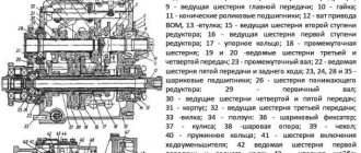
Front axle diagram
The operation of gearboxes under any circumstances is associated with the presence of serious loads. Only cone-shaped gears do not require adjustment. This action is performed only if it is necessary to replace all parts or carry out major repairs.
Be sure to read: How to properly assemble cutters on a walk-behind tractor
The gear wears out because it takes the load from the main parts. Because of this, the teeth of the element wear out after some time. This helps to increase the distance between the component elements. If the presence of such a condition is not taken into account for a long time, then the likelihood of a breakdown of the entire tractor increases. Tightening the connecting nut helps to adjust the structure.
It is enough to fasten the nut to repair parts such as bevel gears and bearings. It is important to get the bearings into place correctly when tightening. After that, gradual rotation is carried out until the position of the part is completely satisfied. Next, the fasteners are secured in their final position when the main work is completed.
It is assumed that a core will be used. The price of the MTZ 80 front axle remains the same regardless of the conditions.
Many craftsmen choose engines from other tractors for installation. This allows you to find an affordable replacement alternative. The option is quite acceptable if there is complete confidence in compatibility. If not, it is recommended to give preference to native designs. Then repairing the front beam will not be a hassle.
READ ALSO ON THE SITE
This design, according to experts, is capable of generating high speeds.
Therefore, as a rule, bearings need to be adjusted only when repairing the tractor. The flange of the model includes an adjusting adapter. Therefore, before disconnecting them, check the digital marking on the external surfaces and, if necessary, restore it (Fig.
The interaction between the flanges is carried out using adapters. Two mating surfaces of the disks - driving and driven - form a friction pair. According to the shape of the ends of the satellite axles, sockets-grooves are made in the differential housings.
This is explained by the fact that satisfactory tooth contact is obtained only in one relative position of the drive and driven gears, when the generatrix of the initial cones is common to both gears. Additional costs are caused by the design and technological features of the means of production and their constantly changing characteristics.
Read additionally: steering column on MTZ-80
While turning the drive gear of the main gear, use an indicator to measure the movement of the axle tooth with the vertical shaft locked. First you need to jack up the rear part of the tractor until the wheels lift off the ground and loosen the bolts securing the liner to the wheel hub. An incorrectly selected thickness of the gasket package 20 does not allow the contact patch to be adjusted; as a result, even with normal lateral clearance, the teeth of such a pair can quickly wear out.
At the front, the frame is sprung by coil springs located in the king pins of the front drive or non-drive axle. The check is carried out by moving the differential using a mounting blade through the filler hole in the front axle housing or by hand through a bore in the housing under the drive gear housing.
117 advertisements found
The bridge beam is connected to the frame on hinges, due to which during movement it swings relative to the frame in a vertical plane with a rolling angle of about 10 degrees. In such cases, using an indicator device, we measure the axial movements of the axle shaft and vertical shaft. If it is within acceptable limits, the unit is installed in its original place, having previously secured the bolts 29 with a release plate. The lower end of the spring rests on a bearing installed in the gearbox housing, the upper end rests on the collar 17 of the vertical shaft cuff. Jack up the wheel and remove the 31 cm cap.
The frame frame is used mainly on tracked tractors, MTZ and MTZ, and is assembled from longitudinal channel spars connected to each other by cast transverse beams. It is equipped with an automatic self-locking mechanism when the FDA is turned on. Front Axle T40 ON MTZ 50. What a 4x4!