The bridges lay in the garage for 10 years awaiting their fate. Well, or rather, when I grow up and start working on the car.
In appearance, the rear axle was scary, for some reason it seemed that there would be problems with it, but it turned out to be the other way around.
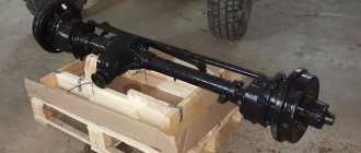
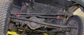
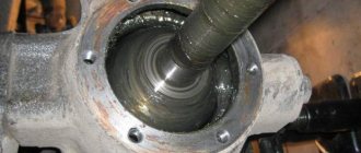
Rear axle dismantled
The work with the rear axle was over and the fun began. I had thoughts that now I would quickly check if everything was in order, prepare it for painting and paint it, but that was not the case. I begin to disassemble the right gearbox and see that all the grease is red (a mixture of grease and rust), then I realized that there would be a lot of work. In general, the bridge was dismantled. All the bushings were replaced (they still had to be unrolled), CV joints, bearings, seals, and king pins were replaced. The bridge was then assembled and ready for painting.
An article on installing bridges will come later, as soon as I finish everything. Well, in principle there is nothing complicated there.
After installing 35 wheels and an ADS gearbox (faster than the Arzamas one), I began to engage 5th gear only from the mountain; it is very difficult to get under way when fully loaded; uphill it is generally better with a lower gear. I decided to install military axles instead of the spicer while maintaining the spring suspension. A long search yielded results and a couple of bridges were purchased. The epic of transporting them has begun! I assumed that they were not light, but I could not even imagine that they weigh so much! The rear axle was put into the UAZ more or less easily, but the front axle was even heavier; the three of us lifted it into the car with great effort (the car is lifted and + 35 wheels need to be lifted quite high). Same problem with uploading! Now I'm busy rebuilding! At the moment I completely disassembled the rear axle
I'll post a photo a little later
I disassembled the front axle, it turned out everything was not as bad as the rear axle shaft was fine! The only replacements are oil seals, pivots, gaskets, and every little thing that the army men managed to unscrew! somewhere around 4000r.
+ There is still a problem with the brakes; it won’t be possible to leave the original ones because there are no spare parts. you will have to put it forward from the Volga... the back is simpler...
I took everything apart!))) Surprisingly, all the bolts came out! Before disassembly, I read several reports on the bulkhead where people wrote about broken bolts. Luckily this didn't happen! I bought some pieces of hardware. Brake cylinders from the Volga with self-supplies! Gaskets and sundries
By the way, the recently purchased pliers turned out to be a valuable thing. It was assumed that drain plugs with torn hexagons would be problematic to unscrew! You will have to weld the bolt and unscrew it. The miracle pliers unscrewed all the plugs without problems, even when the grip was about a millimeter, which I was incredibly happy about!
06.06.11 Today I bought the remaining pieces of hardware and tomorrow I will start collecting (Photos will follow!)
06/09/11 Having disassembled the rear axle, it was discovered that the people who had sorted it out before me were complete, , , , , , , , (Amateurs)! While they were disassembling it to replace the main pair, a tooth was discovered in the bridge housing
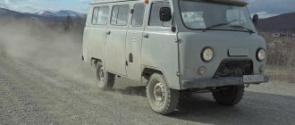
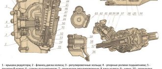
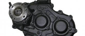
UAZ is a common car on Russian roads. Its design features allow you to move without problems on paved areas, as well as off-road. Repairing the front axle of a UAZ is impossible without knowing the diagram of the wheel gearbox, the design of which is similar to a similar part of the rear axle. The key difference is the peculiarity of fastening and installation of the main gear, the design parameters of the ball bearing located in a special compartment-cup.
How to identify faults and repair the front axle of a UAZ
UAZ is a common car on Russian roads. Its design features allow you to move without problems on paved areas, as well as off-road. Repairing the front axle of a UAZ is impossible without knowing the diagram of the wheel gearbox, the design of which is similar to a similar part of the rear axle. The key difference is the peculiarity of fastening and installation of the main gear, the design parameters of the ball bearing located in a special compartment-cup.
UAZ Hunter. Repair of the front axle gearbox. Part 1.
Having driven into the pit, I saw the following...
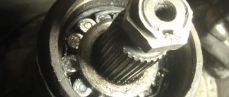
The gearbox shank is loose. As they say, “sit on the edge and dangle your foot”...
Two bearings were completely destroyed. I suspect that the third one, the one at the end of the drive gear, is also not so hot. The rollers just spilled out and the shank was pulled out by hand. How the guys didn’t lose him along the way is a mystery. Lucky, however...
Inside the gearbox it’s dirty and dark))) That’s the humor.
In general, you need to remove the front axle for troubleshooting. It is already clear that new shank bearings, a large adjusting washer, washers, an oil seal ring and a shank oil seal are needed. An autopsy will show what else is needed.
It is better to remove the front axle completely. In a vertical position it is very convenient to troubleshoot and adjust.
To do this, first of all we disconnect the “sticks”, the lower shock absorber mount and the stabilizer bar mounting bracket. Speaking of the last one. I generally believe that it is not needed on an SUV. It hurts and stifles the articulation of the front axle. We must suggest that the owner of the car dismantle it, so to speak. The difference in cross-country ability will be significant!
Then unscrew and remove the springs.
After that, using a puller or other available devices, we remove all the ball joints.
We unscrew the tubes from the brake tee that go to different sides of the bridge and, in my case, lower the bridge onto the transmission stand.
After which we calmly roll up to the edge of the pit, where, placing it on stands, I will halve it...
Device and characteristics
The design of the UAZ front axle in older models has few differences from the similar design in new models (Spicer). The main differences lie in the design of the crankcase, the dimensions of the components of the drive gear and differential, and in a number of units used.
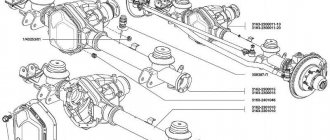
The design of the old model is in many ways similar to the rear axle of the UAZ and consists of the following components:
- The key place is occupied by the split crankcase, consisting of 2 separate parts.
- Each half is equipped with press-in housings with internal axle shafts.
- Safety valves on the casings, responsible for controlling the growth of oil volume in the mechanism.
- The differential and main gear of the casing are made according to the standard design: a small-diameter drive gear is located in the horizontal plane, in contact with the cardan.
- The large driven gear in the longitudinal plane is in mesh with the main gear. It has a built-in differential of 4 satellites.
- The edges of the crankcase housing are equipped with pivot joints made of ball joints with a rotating housing.
A design feature of the Spicer bridge is the presence of a contact system between the wheel hub and the axle shaft. It is a coupling responsible for connecting and disconnecting 2 elements. The mechanism ensures the transmission of torque to the wheel from the differential. The disconnected clutch leads to free rotation of the wheel on the axle, and the vehicle receives a 4*2 wheel arrangement. The engaged clutch leads to the connection of the hub, differential and axle shaft, the car turns into a 4*4 all-wheel drive.
Old UAZ car models were distinguished by the presence of hubs with drum brake units.
Their wheel rotation angle is no more than 29°. The knuckle and linkage arms connected to each other are a wheelbase control tool. In new models (Spicer), the angle of rotation reaches 32°. The rest of the bridge structure is similar.
What is the difference between a UAZ military bridge and a civilian one?
The military axle, unlike the civilian Spicer front axle, is equipped with final drives. This design feature caused the following differences between military models:
- Gear axles are located 4 cm above the wheels. This difference helps to increase vehicle clearance - the distance between the supporting surface and the bottom of the bridge.
- The main pair is smaller in size and has a small number of large teeth, which increases the reliability of the design. The unit weighs more.
- The gear ratio is 5.38 (traction, but not speed).
- The length of the rear propeller shaft is 1 cm shorter.
Advantages of military bridge models:
- increased ground clearance by 8 cm;
- high torque, allowing you to transport heavy objects, tow and move at low speeds over difficult terrain;
- load evenly distributed between the main and final drives;
- larger teeth increase reliability;
- limited slip differential for off-road driving.
The military design of the UAZ was thought out to accompany tank colonies, which indicates the power and reliability of the design.
Rear axle UAZ 3151
- Repair manuals
- Repair manual for UAZ 3151 1985-2008.
- Rear axle
POSSIBLE MALFUNCTIONS OF THE REAR AXLE, THEIR CAUSES AND REMEDY METHODS
Maintenance
Maintenance of the rear axle consists of maintaining the oil level in the crankcase and replacing it in a timely manner, checking the seals, and timely detecting and eliminating axial clearances in the final drive gears. Periodically clean the safety valve and tighten all fasteners.
If the oil in the crankcase is heavily contaminated or there are metal particles in it, wash the crankcase with kerosene before adding fresh oil. To flush, pour 1–1.5 liters of kerosene into the crankcase; raise the wheels, start the engine and let it run for 1.0–1.5 minutes, then drain the kerosene and fill with fresh oil.
| Rice. 3.79. Rear axle: 1 – safety valve; 2 – differential bearing; 3.8 – adjusting shims; 4 – rear bearing of the drive gear; 5* – adjusting ring; 6 – oil removal ring; 7 – nut; 9 – drive gear; 10 – front bearing of the drive gear; 11 – thrust washer of the semi-axial gear; 12 – driven gear. (* Not installed since 1991) |
Axial play of the drive gear of the fixed gear is not allowed. Check the clearance by rocking the drive gear by the driveshaft mounting flange. If an axial play of the drive gear of more than 0.05 mm appears during vehicle operation, tighten nut 7 ( ). Tightening torque – 167–206 N m (17–21 kgf m). If the gap does not disappear, make adjustments as indicated in the chapter “Assembling and adjusting rear axle components.”
Axial play of the main drive driven gear is not allowed. Check it by moving the gear through the oil filler hole. To eliminate the gap, add sets of shims of equal thickness between the ends of the differential and bearings.
Do not add shim sets of different thicknesses or install them on the same side of the driven gear because this will lead to disruption of the engagement of worn-in gears and their rapid breakdown.
Repair
Rear axle disassembly
Disassemble the bridge in the following order:
| Rice. 3.80. Installation of the bridge on the stand |
1. Place the bridge on the stand ( ), unscrew the oil filler and oil drain plugs and drain the oil.
2. Unscrew the bolts securing the axle shafts and, using them, remove the axle shafts.
3. Unscrew the nuts and bolts securing the cover and crankcase, and carefully separate the bridge into two parts. Remove the gasket.
4. Remove the differential and driven gear assembly from the housing.
5. Remove the main drive gear. Without disassembling the axle, it is impossible to remove the drive gear, since when pressing the gear and bearing assembly out of the axle housing, the rear bearing (with cylindrical rollers) will rest against the driven gear.
| Rice. 3.81. Pressing out the drive gear |
To remove the drive gear, unscrew and unscrew the nut on the shank, remove the washer and flange, unscrew the bolts and remove the drive gear front bearing cap. Remove the oil removal ring and use a tool to press the drive gear ( ) with the bearing assembly out of the crankcase.
6. Disassemble the differential in the following order:
– Unscrew the bolts securing the driven gear to the satellite box; remove the driven gear;
– unscrew the bolts securing the halves of the satellite box;
– disconnect the right half of the gearbox from the left and remove the differential gears, satellite axles and support washers.
Assessment of the technical condition of parts
After disassembling the bridge, thoroughly rinse the parts in kerosene and inspect.
Gears
with scoring and chipping on the teeth, replace.
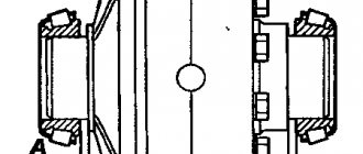
| Rice. 3.82. Pressing out the outer ring of the differential bearing |
| Rice. 3.83. Removing the inner ring of the differential bearing |
| Rice. 3.84. Removing the rear bearing from the drive gear |
| Rice. 3.85. Removing the front bearing from the drive gear |
Bearings
that are worn, replace them. If the bearings and associated parts do not require replacement, then do not press out the bearing rings. Press out the outer rings of the differential bearings ( ) from the crankcase and cover and remove the inner rings ( ) of these bearings using tools. Removal of the rear and front drive gear bearings is shown in and. The end of the neck on which the rear bearing is pressed is open, therefore, press it out only for replacement. When disassembling the axle, do not disassemble the inner and outer rings of the differential and drive gear bearings, and when reassembling, install the bearings that do not need to be replaced in their original places.
Oil removal ring
must have smooth ends. If necessary, sand it to a thickness of at least 5 mm.
Cardan flange.
The end of the flange associated with the oil removal ring must be smooth. If necessary, sand it to a height of at least 53 mm.
Bridge housing.
Remove all roughness and burrs from the seating and adjacent surfaces of the crankcase. Clean the oil channels.
Differentials and axle shafts
. Replace thrust washers, pinion axles, pinions, axle gears and pinion boxes with scoring and severe wear. Replace satellites and semi-axial gears as a set. Replace the side gear thrust washer if its thickness is less than 1.2 mm. If the ends of the satellite box are worn, it is permissible to install washers increased in thickness by 0.1 mm or 0.2 mm.
When repairing the rear and front axles, use the data
And .
Assembly and adjustment of rear axle units
Assemble the differential in the following order:
1. Before assembling the differential, lubricate the axle gears, pinions, thrust washers and pinion axles with transmission oil.
2. Install thrust washers on the journals of the axle gears.
3. Install the axle gear with thrust washer assembly into the left gear box.
4.Install the satellites on the axis of the split cross.
| Rice. 3.86. Pressing out the outer ring of the differential bearing |
5. Install the split cross (
) with satellites in the left satellite box.
| Rice. 3.87. Installation of satellite boxes according to marks |
6. Install the axle gear with thrust washer assembly into the right gear box. Holding the axle gear, install the right satellite cup onto the left one so that the marks ( ) (serial numbers) of both cups are aligned.
7. Connect the halves with bolts and tighten them. Tightening torque 32–40 Nm (3.2–4.0 kgf).
8. Install the main drive driven gear onto the gearbox, aligning the bolt holes. Install the bolts and tighten them. Tightening torque 98–137 N m (10–14 kgf m).
For the assembled differential, the axle gears must be rotated using a splined mandrel from a force of no more than 59 N (6 kgf) applied over a radius of 80 mm.
Adjusting the differential bearings
carry out (if they are replaced) in the following order:
| Rice. 3.88. Preliminary pressing of the inner rings of the differential bearings |
1. Press the inner rings of the bearings ( ) of the differential onto the journals of the assembled differential so that there is a gap of 3.5–4.0 mm between the ends of the gearbox and the ends of the inner rings of the bearings.
| Rice. 3.89. Rolling differential bearing rollers |
2. Install the differential assembly into the crankcase, then the gasket and crankcase cover and, turning the cover by the casing, roll the bearings so that the rollers are in the correct position ( ). Then use bolts and nuts to evenly connect the cover to the crankcase.
| Rice. 3.90. Measuring gaps when adjusting differential bearings |
| Rice. 3.91. Gaps A and A1 between the ends of the inner rings of bearings and the gearbox |
3. Unscrew the bolts again, carefully remove the cover, remove the differential from the crankcase and use a feeler gauge to measure the gaps A and A1 ( and ) between the ends of the inner rings of the bearings and the gearbox.
4. Select a package of gaskets with a thickness calculated according to the formula:
s = A + A1 + 0.1,
where: s
– thickness of the gasket package, mm;
A
and
A1
– gaps between the ends of the inner rings of bearings and the satellite box, mm;
0,1
– constant value (to ensure preload), mm.
5. Remove the differential bearing inner races. Divide the selected pack of gaskets approximately in half. Install the gaskets on the journals of the satellite gearbox and press the inner rings of the bearings until they stop.
Assembling and adjusting the drive gear bearings
do it in the following order:
| Rice. 3.92. Punching the end of the shank after pressing the bearing: A – place of punching |
| Rice. 3.93. Installing the spacer sleeve and shims for the front drive gear bearing |
1. Press the bearings onto the drive gear. After pressing the rear support bearing with cylindrical rollers, open the end of the shank onto which it is pressed ( ). Place the spacer sleeve ( ) and shims for the front bearing (double-row bevel) of the drive gear between the inner rings.
2. Install adjusting ring 5 (see) of drive gear 9 (not installed since 1991).
| Rice. 3.94. Checking the tightness of the drive gear bearings |
3. Press the drive gear assembly with bearings into the crankcase until it stops and adjust the front bearing preload by changing the thickness of the gasket pack 8 and tightening the nut 7 until it stops. In this case, the oil removal ring 6 and the flange must be installed on the gear shaft, and the front bearing cover must be removed so that the friction of the cuff on the flange does not affect the measurement readings. To reduce the tension, add spacers, to increase it, remove it. With proper adjustment, there should be no axial play, and the spring dynamometer should show a force of 15–30 N (1.5–3 kgf) for run-in bearings and 20–35 N (2.0–3.5 kgf) for new bearings when turning the gear behind the hole in the flange ( ).
4. After completing the adjustment, remove the flange and install the gaskets and drive gear front bearing cap. Secure the cover with bolts. Place the flange, tighten nut 7 (see) and secure it with a cotter pin. Tightening torque 167–206 N m (17–21 kgf m).
Adjusting the side clearance and position of the main gears
After adjusting the drive gear and differential bearings, proceed in the following order:
1. Install the differential assembly with adjusted bearings into the crankcase. Install the gasket on the plane of the crankcase connector with the cover. Install the crankcase cover and secure with bolts.
| Rice. 3.95. Checking the lateral clearance in the meshing of the main gear gears |
2. Measure the lateral clearance between the teeth of the drive and driven gears, which should be 0.2–0.6 mm. Take measurements on the drive gear flange at a radius of 40 mm ( ).
Adjust the side clearance by moving shims 3 (see) from one side of the differential box to the other. If you remove shims from the side of the driven gear, the gap in the mesh increases, but if you add shims, the gap decreases. Rearrange the gaskets without changing their quantity, as this will disrupt the tension of the differential bearings.
| Rice. 3.96. Contact patch of the main gear gears: I – forward side; II – reverse side; 1 – correct contact in the meshing of gears when checking under a light load; 2 – contact at the top of the tooth (to correct it, move the drive gear towards the driven one); 3 – contact on the tooth root (to correct it, the drive gear should be moved away from the driven gear); 4 – contact at the narrow end of the tooth (to correct it, move the driven gear away from the driving gear); 5 – contact at the wide end of the tooth (to correct it, move the driven gear towards the driving gear) |
3. On axles with an adjusting ring 5 (see ), check the engagement of the gears along the contact patch. To do this, paint the teeth of the driven gear with paint. Keep in mind that very liquid paint spreads, and too thick paint cannot be squeezed out of the spaces between the teeth. Then, using the axle shafts, slow down the driven gear and rotate the drive gear in both directions until a clear contact patch is identified. Typical contact pattern positions on driven gear teeth and how to correct improper contact are shown. Move the drive gear by installing adjusting ring 5 (see) of a different thickness. Move the driven gear by rearranging the gaskets of the 3 differential bearings.
| Note Perform the specified check of gear engagement on axles with final drives. |
Rear axle assembly
Assemble the rear axle after adjusting the gear engagement in the following order:
| Rice. 3.97. Measuring the gap between the bearing cap and the crankcase to select gaskets |
1. Install the gasket pack between the end of the front pinion bearing cap and the crankcase. The thickness of the package should be 1.3 times the gap ( ) between the ends of the cover and crankcase. If necessary, increase the thickness of the bag by 1.4 times.
2. Install the drive gear front bearing cap and collar assembly and secure with bolts.
3. Install the flange and washer. Tighten nut 7 (see ) as far as possible so that the slots in it coincide with the holes in the gear shank and secure with a cotter pin. Tightening torque 167–206 N m (17–21 kgf m). Do not unscrew the nut to match the groove and the hole for the cotter pin.
4. Install the differential with the driven gear and bearings assembled into the axle housing.
5. Install a gasket between the crankcase and the cover.
6. Install the crankcase cover so that both spring pads are at the top of the axle. Connect the cover and crankcase using bolts and nuts.
7. While turning the drive gear, check for any binding or snagging in the assembled axle. After assembling the bridge, check its heating while the vehicle is moving. If the crankcase gets very hot (over 90 °C), check that the bearings are adjusted correctly.
↓ Comments ↓
1.Operation and Maintenance
1.0 Operation and maintenance 1.1 Maintenance 1.2 Scope of work by type of maintenance 1.3 Vehicle lubrication
2. General information
2.0 General information
3. Engine
3.0 Engine 3.1 Crank mechanism 3.2 Possible engine malfunctions, their causes and methods of elimination 3.3 Gas distribution mechanism 3.4 Lubrication system 3.5 Cooling system 3.6 Power system 3.7 Exhaust system 3.8 Engine mounting 3.9 Checking the technical condition of the engine
4. Transmission
4.0 Transmission 4.1. Clutch 4.2. Gearbox 4.3. Transfer case 4.4 Drive axles 4.5. Rear axle 4.6. Front axle 4.7 Axles with final drives
5. Chassis
5.0 Chassis 5.1. Car suspension 5.2. Hubs, wheels and tires
6. Steering
6.0 Steering 6.1 Maintenance 6.2 Possible steering malfunctions, their causes and solutions
7. Brake system
7.0 Brake system 7.1 Service brake system 7.2 Possible malfunctions of the service brake system, their causes and methods of elimination 7.3 Parking brake system 7.4 Possible malfunctions of the parking brake system, their causes and methods of elimination
8. Electrical equipment
8.0 Electrical equipment 8.1 Battery 8.2 Possible malfunctions of the battery, their causes and methods of elimination 8.3 Generator 8.4 Possible malfunctions of the generator, their causes and methods of elimination 8.5 Possible malfunctions of the voltage regulator, their causes and methods of elimination 8.6 Starter 8.7 Possible malfunctions of the starter, their causes and methods elimination 8.8 Non-contact ignition system 8.9 Possible malfunctions of the ignition system, their causes and methods of elimination
9. Car body and cabin
9.0 Body and cabin of vehicles 9.1 Body of vehicles of the UAZ-31512 family 9.2 Body and cabin of vehicles of the UAZ-3741 family 9.3 Frame and towing device
10. Applications
10.0 Applications 10.1 Appendix 1. rolling bearings used in components and assemblies of automobiles 10.2 Appendix 2. special tools and devices for disassembling and assembling components and assemblies of automobiles
How to turn on the front axle on a UAZ
Engaging the front gear may be necessary if it is necessary to turn from an asphalt road surface onto a country road or terrain with potholes and mud. In the new conditions, rear-wheel drive will not cope with difficulties. Engaged front-wheel drive is a means of solving the problem.
System startup sequence:
- Stop the car and check the operation of the front wheel quick release clutch. It is turned on by turning the wheels clockwise until they stop.
- Move the rightmost lever forward to switch the front wheels to driving status. Now their rotation will be equivalent to the rear.
If the road condition worsens while driving, it becomes more and more difficult to continue driving, the engine stalls, you need to stop the vehicle and engage a lower gear. To do this, you will need to move the middle lever back. In low gear, all 4 speeds are available, and driving becomes easy and smooth again.
UAZ shank bearings in Balashikha
“One-click ordering” is available on the seller’s website. To go to the site, click “Go to store”
“One-click ordering” is available on the seller’s website. To go to the site, click “Go to store”
“One-click ordering” is available on the seller’s website. To go to the site, click “Go to store”
“One-click ordering” is available on the seller’s website. To go to the site, click “Go to store”
“One-click ordering” is available on the seller’s website. To go to the site, click “Go to store”
Malfunctions and repair work
Common malfunctions of the UAZ front axle and possible repairs:
- Leakage of lubricating fluids. Check the tubes and connecting elements for mechanical damage - the cuffs and flange for functionality, the oil container for the optimal fluid level.
- High wear of fasteners.
- Bearing defects caused by the use of poor quality material by the car plant.
- Broken axle teeth. Adjustment will not help; parts need to be replaced.
- Mechanical defects of the beam.
- Wear of elements. The situation is resolved by replacing it with new spare parts.
- Poor grip of the bearings and main gears indicates the need for tension adjustment.
Bridge repairs begin after diagnosing and searching for the cause of problems in the functioning of the mechanism, which are diverse:
- transmission components of a rear-wheel drive vehicle are faulty due to regular movement over difficult terrain;
- use of consumables and lubricants of unsuitable quality;
- Failure to monitor tire pressure can lead to shaft and bearing failures.
Most often, car owners are faced with a violation of the axial space of the kingpins and are knocked out of the required position. To diagnose, you need to jack up the front of the vehicle and move the wheel in a vertical plane. The presence of axial play indicates the need to adjust the clearance of the pins.
How to adjust bridges
You can adjust the UAZ axles yourself. This will require a number of tools and good knowledge of the mechanism. Access to the necessary parts and assemblies is possible after dismantling the structure and separating the crankcase parts. The first sign of the need to adjust the gearbox is loud noise and malfunctions of the part. Such work is required after diagnosing the condition of bridges. Adjustment includes a number of activities.
At the first stages of repair work, ensure that the nuts of the brake elements can be loosened freely. The tools you will need are a split wrench, brake fluid and a mixture of WD-40. The bridge is dismantled as follows:
- remove the fasteners between the drive gear flange and the propeller shaft;
- secure the shaft to the side;
- place the front part of the vehicle on jacks, raising the wheels above the surface;
- additionally install safety supports;
- remove the nut between the brake pipe and hose and close the hole with a plug to avoid large losses of fluid;
- after removing the lower fasteners and moving the shock absorbers from the axle, the bridge will lower;
- remove the stepladder nuts and roll out the bridge (without wheels it weighs more than 100 kg).
For adjustment and repair work, you will again need a split wrench, a metal corner with pins, a universal puller, a container with brake fluid, transmission oil (if you don’t want to fill in the old one), a set of bearing spacers for adjusting the driven gear and a micrometer. Preparatory work:
- remove 10 bolts connecting the axle shafts to the hubs;
- remove the axle shaft from the crankcase;
- Unscrew the fasteners of the brake pipes;
- remove the tee from the bracket;
- remove the connecting elements between the crankcase parts, keeping the gasket;
- Remove the differential housing and driven gear, outer rings.
The main support of the drive gear, which determines the reliability of the bridge, is a tapered roller bearing located in the front part, consisting of 2 rows. A similar part on the opposite side performs an auxiliary function. To repair, you will need to remove the right drive gear by removing the bolts.
All disassembled components should be inspected for wear and replaced if necessary. The shims are located in the middle of the inner rings of the bearing. Their thickness is measured with a micrometer, the part with the smallest value is removed to create preload in the bearing. Adjust the part until the dynamometer shows a resistance of no more than 3.5 kgf. Otherwise, you will need to remove another gasket. Tight turning indicates the need to increase the thickness of the gasket pack. After determining the desired value, you can put the unit back together.
The next step is to adjust the differential bearings:
- press in the outer and inner rings;
- mount the differential with the main gear into the crankcase;
- install the gasket;
- separate the crankcase parts;
- remove the differential, check the clearance of the differential and bearing rings;
- install the main gear mechanism on the right side of the crankcase;
- install the drive shaft;
- pull together the crankcase halves, observing the required gap size, adjusting it if necessary with cardboard spacers.
After all the work, it is necessary to assemble the bridge back and install it on the car. At the same time, you can lubricate the parts and replace worn fasteners.
How to remove the shank
It is possible to repair, replace and adjust the shank only after removing it. To do this, it is necessary to check the backlash at the beginning of work. Then you will need to perform the following operations:
- Turn the cardan clockwise until it stops. At this point, make a mark on the body of the structure.
- Turn the cardan in the opposite direction until it stops. Make a second mark.
- Control between the designated positions of the maximum permissible distance is 11 mm.
- Removing the cardan flange, tightening the nuts.
- Checking the backlash. Removing the front axle.
- Removing the nut and shank.
- Removing oily liquid.
After this, the wheels and steering controls can be removed.
How to shorten a bridge
Before shortening the axles, it is necessary to remove the axle shafts. You will need to perform the following manipulations:
- cut the stocking;
- select a pipe of suitable diameter and install it inside;
- welding work;
- cut off the axle shaft;
- cut a hole on a lathe and mount the axle shaft into it;
- Weld the resulting structure on both sides, remove excess parts.
In this way you can make a bridge for 80 cm gauge.
Replacing the bearing and shank oil seal
Replacing the front axle shank bearing and oil seal includes the following activities:
- Dismantling old parts (bearings and oil seal).
- Replacing a worn bushing to prevent damage to new components.
- Installation of new parts, flange and fasteners.
How to remove the UAZ gearbox bearing race.
To watch online, click on the video ⤵
We knock out the outer bearing race from the differential housing of the axle. Hunter More details
Pullers for UAZ axle repair Read more
Replacement of gearbox bearings on the rear axle of a UAZ. Kozlik bridges Kolkhoznye. More details
How to remove the bearing race from the housing Read more
Replacing the UAZ Patriot shank bearing without a puller Read more
SUPER WAY to remove the bearing race. More details
How to remove the outer race of the shank needle bearing in the rear gearbox MT-10-36 Read more
super removing the bearing from the shank. More details
Tool for removing the bearing sleeve from the rear axle shank of a VAZ. VAZ in the village. More details
Replacing bearings and seals in the rear axle and transfer case of the UAZ Patriot Read more
Removing a tapered bearing from a quill More details
Remove the bearing race from the axle of a UAZ, GAZ, etc. More details
Adjusting the UAZ shank Read more