The KamAZ-43114 truck, equipped with an all-wheel drive system, is used in the civil and military sphere. High performance became the reason for the car’s use in the Paris-Dakar rally as a technical support vehicle. An army truck is used to transport personnel and install various weapons and equipment. The civilian version is used for the construction of fire trucks and the installation of special superstructures.
Device
The car is based on a frame made up of 2 side members and several cross members. The frame is available in a single version with a base of 3340 mm. The rear cross member of the frame is equipped with a towing device and an outlet for connecting the trailer brakes to the pneumatic system of the tractor.
The drive axles are unified in design and have a drive-through design. The front axle drive cannot be switched off. The axle suspension is spring, the front axle has additional hydraulic shock absorbers. The steering is equipped with a hydraulic booster.
Above the engine is a fully metal cabin designed for a driver and 2 passengers. The driver's seat is mounted on a spring shock absorber. Adjustable for backrest angle, distance from the pedals and driver weight.
The onboard version of KamAZ-43114-15 is equipped with an all-metal platform with the ability to install an awning and a cabin with a berth behind the seats. The floor of the platform is covered with planks; it is possible to install folding benches to accommodate 30 people. The model 43114 chassis comes with a cab without a sleeper, but a long cab is also available on request. The power unit is covered with soundproofing screens, which increase the acoustic comfort in the cabin.
Cabin KAMAZ 65115
In 2010, these cars received completely updated workplaces for drivers.
For example, the sleeping areas were removed, but the roof and higher ceilings were used. We added a plastic bumper and rectangular headlights. The rear view mirrors and wheel arches have become larger and more modern.
Deflectors are located on each side of the cabin. There is a windshield wiper with at least three blades.
A standard driver's seat with lateral support is used. There are kits with more expensive and comfortable equipment, where the driver can customize almost everything. The steering column can also be adjusted, although this requires additional effort.
Steps and handrails provide easy access to the cabin, even given the high location. Drivers of any height can easily be accommodated inside; panoramic mirrors provide full visibility.
Interesting! Technical characteristics of KamAZ-43118 in numbers and modifications
Additionally there is a tool box.
Specifications
The all-terrain vehicle has a load capacity from 6100 to 8600 kg (depending on the superstructure). The side platform is 4.8 m long and equipped with metal sides 500 mm high. The machine is equipped with a 10-speed transmission, consisting of a gearbox with a divider and an additional transfer gearbox. All gears, except first, are equipped with shift synchronizers. The transfer gearbox contains a center differential lock with an electro-pneumatic drive.
The maximum speed of the all-terrain vehicle when driving on the highway is 90 km/h.
The 43114 all-terrain vehicle uses drum brakes with the following parameters:
- pneumatic drive;
- drum diameter 400 mm;
- The width of the working part of the block is 140 mm.
KamAZ-43114 technical characteristics are not inferior to imported trucks with all-wheel drive. Cross-country ability is ensured by wheels equipped with pneumatic tires with a tube of size 390/95R20 or 425/85R21, equipped with an air supply system. The large size of the tires made it possible to obtain a ground clearance of 360 mm, sufficient for confident off-road driving.
Upon request, the machines are equipped with a winch mounted in front of the cabin. The winch is equipped with a worm gear and a band brake mechanism. The winch is driven by a cardan shaft from a power take-off mounted on the gearbox housing. A cable wound on a drum has a forward extension of up to 76.5 m and a backward extension of up to 83.5 m. When using a chain hoist, the traction force when extending the cable forward is up to 10,800 kgf, and backward – up to 15,400 kgf.
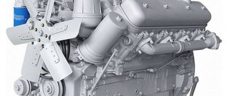
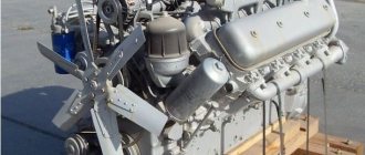
Engine
The 43114 all-terrain vehicle uses a 240-horsepower diesel engine model 740-31-240 with reduced fuel consumption. The engine's performance is enhanced thanks to a turbocharger and a radiator designed to cool the air compressed by the compressor. The fuel supply system allows you to comply with Euro-2 requirements. The engine is built in a V-shape, has 8 cylinders with a displacement of 10850 cm³. Motor cooling is liquid, forced.
The fuel consumption of KamAZ-43114 declared by the plant is 36 liters per 100 km. In severe off-road conditions, consumption increases by 1.5-2 times. To reduce fuel consumption, an autonomous heater is used, making it easier to start the engine in winter.
Dimensions and weight characteristics
Dimensions and weight of the onboard version of the all-terrain vehicle:
- length - 7730 mm;
- height - 3375 mm;
- the weight of the equipped vehicle is 9030 kg.
The fuel supply is located in 2 tanks located on the frame side members behind the cabin. Tank volume is 170 or 210 l. When using small tanks, an additional capacity of 125 liters of liquid is installed.
All-terrain vehicle refueling tanks:
- cooling system with heater circuit - 36.6 l;
- power unit lubrication system - 33 l;
- amplifier reservoir - 4.2 l;
- front axle housing - 5.3 l;
- rear bogie axle housings - 7.0 l;
- gearbox - 8.5 l;
- transfer gearbox - 5.4 l;
- clutch control reservoir - 0.28 l;
- winch drive gearbox - 3.9 l.
Service station regulations for KamAZ engine
During the initial period of operation the following is carried out:
— daily maintenance (EO);
— maintenance of TO-1000, performed once after the first 500... 1000 km;
— maintenance of TO-5500, performed once in the interval of 4500...5500 km.
— the first maintenance (TO-1) is performed for the first time in the interval of 10,000...11,000 km;
— the second maintenance (TO-2) is performed in the interval of 15500... 16500 km.
Maintenance during the initial period of operation is performed at specified intervals, regardless of the categories of operating conditions.
During the initial period of operation, engine parts are worn in, therefore, during maintenance, preventive, fastening, lubrication, cleaning and adjustment work must be carried out carefully, which will ensure reliable and economical operation of the engine, as well as a long service life.
During the main period of operation the following are carried out:
— daily maintenance;
— first maintenance (TO-1), performed in the interval of 5000...6000 km (data are given for the first category of operating conditions);
— second maintenance (TO-2), performed in the interval 14800...18100 km;
— seasonal maintenance (STO) performed twice a year - in spring and autumn. Work to prepare for the winter season is included in additional autumn work.
The mileage between regular maintenance services during the main period of operation depends on the category of operating conditions.
Each type of maintenance during the main period of operation has an individual list of operations, i.e. not a single TO-1 operation is included in either TO-2 or STO, in turn, TO-2 operations are not included in the STO. It is allowed to perform several types of maintenance simultaneously, for example, TO-1 and TO-2, TO-1 and STO, TO-2 and STO, or TO-1, TO-2 and STO.
Below are lists of works required for engine maintenance during the initial (Table 4) and main (Table 5) periods of operation.
data required for maintenance is given in Appendices D and E.
The frequency of oil and coolant changes is given in the chemical chart (Appendix E ).
LIST OF ENGINE MAINTENANCE WORKS PERFORMED DURING THE INITIAL PERIOD OF OPERATION
Table 4
| Contents of work | Similar work was carried out. new period of operation | |
| Table number 5 | Wil TO | |
| Daily Maintenance (DM) | ||
| Carry out work on the SW according to Table 5 | 1-3 | EO |
| Maintenance of TO-1000 | ||
| Clean the engine from dust and dirt. Check: | ||
| — condition and tightness of units and pipes of the fuel supply system, lubrication system, cooling system; | 3 | EO |
| — tightness of drain and oil supply lines to turbochargers | 3 | EO |
| Pin: — elements of the air path connection, paying special attention to the path from the air filter to the engine; | 1 | TO-2 |
| — injector mounting brackets; | — | — |
| — exhaust manifolds; | 1 | TO-1 |
| - turbochargers; | 1 | TO-1 |
| — turbine and compressor housings. | 1 | TO-1 |
| Adjust: — thermal clearances of the valves of the gas distribution mechanism, having previously checked the tightness of the bolts securing the cylinder heads and the nuts of the rocker arms; | 4 | TO-2 |
| — tension of drive belts. | 3 | TO-2 |
| Maintenance of TO-5500 | ||
| Clean the engine from dust and dirt | ||
| Change: | ||
| — oil in the engine lubrication system; | 5 | TO-2 |
| — filter elements of the oil purification filter; | 6 | TO-2 |
| — filter elements for fine fuel filter. | 7 | TO-2 |
LIST OF WORK PERFORMED DURING THE MAIN PERIOD OF OPERATION
Table 5
| Contents of work | Technical requirements and method of work | Devices, tools, accessories and materials |
| Daily Maintenance (DM) | ||
| Clean the engine from dirt and dust | ||
| 1 Bring the oil level in the engine oil sump to normal | Check the oil level after 4...5 minutes. after stopping the engine, installing the product on a flat horizontal platform. The level should be near the “B” mark, which corresponds to the required amount of oil in the engine. | Oil container, rags |
| 2 Bring the fluid level in the cooling system to normal | The level is checked on a cold engine. The level should be between o and “MAX” on the side surface. | Coolant container |
| 3 Check: | Condition of the alternator drive belt and water pump. Tightness of the system for supplying and draining oil from turbochargers. Engine power system connections. | Key S=17×19, screwdriver |
| Maintenance TO-1 | ||
| Clean the engine from dirt and dust. | ||
| 1 Check | Operation of turbochargers (auditory) with the engine running. Fastening turbocharger nuts, bolts and nuts for fastening manifolds and pipes of the intake and exhaust system. | Container, rags Key S=10, 13, 17, 19. |
| 2 Drain sediment from coarse and fine fuel filters | Drain the sediment until clean fuel appears, unscrewing the drain plugs two or three turns. | Key S=14, container for draining sediment |
| Maintenance TO-2 | ||
| Clean the engine from dirt and dust | ||
| 1 Check the tightness of the engine intake and exhaust systems | To avoid failure and swelling of the hoses, the pressure supplied to the air intake tract should not exceed 20 kPa (0.2 kgf/cm2). Identify leaks by escaping smoke. If smoke does not come out within 3 minutes, then the intake tract is sealed. | Device I 801.49.000 |
| 2 Lubricate the water pump bearings (only for engines with a fan located above the crankshaft axis). | Lubricate until fresh lubricant appears from the inspection hole. | Solid fuel supercharger models 390-M, 142 |
| 3 Adjust the tension of the drive belts | Adjust the tension of the drive belts in accordance with the recommendations given in the section “Cooling system” | Keys S=13, 14, 17, device for checking drive belt tension. |
| 4 Adjust the thermal clearances of the gas distribution mechanism, first checking the tightness of the cylinder head bolts and rocker arm nuts | Gap size on a cold engine: - for the intake valve - 0.25 - 0.30 mm; - for the exhaust valve - 0.35 - 0.40 mm. For cylinders 1, 2, 3 and 4 the front valve is inlet, and for cylinders 5, 6, 7 and 8 it is exhaust. The clearances should be adjusted on a cold engine or after stopping the engine, no earlier than after 30 minutes. In this case, the fuel supply must be turned off. Thermal clearances are adjusted simultaneously in two cylinders, following the operating order one after the other, during the compression strokes (power stroke) in these cylinders. The valves of the adjustable cylinders must be closed at this moment. When adjusting, the crankshaft is installed sequentially in positions 1...4, which are determined by its rotation relative to the position of the start of fuel injection in the first cylinder at the angle indicated below: — crankshaft position 1 — 2 — 3 — 4; — rotation angle, degrees — 60-240-420-600; — cylinder numbers of adjustable valves 1; 5, 4; 2, 6;3, 7; 8. | Device I 801.14.000 for adjusting valves, set of feeler gauges No. 2, heads S=17, 19, crowbar for turning the crankshaft, torque wrench. |
The numbering scheme for engine cylinders and fuel injection pumps is shown in the figure.
Drawing. Scheme of engine numbering and location of high-pressure fuel pump sections: 1 - engine; 2 — high pressure fuel pump; 3 - flywheel.
The sequence of operations when adjusting the gaps is as follows:
-remove the cylinder head covers;
-check the tightness of the cylinder head bolts;
- pull out the lock mounted on the flywheel housing, turn it 90° and set it to the lower position;
-remove the hatch cover at the bottom of the clutch housing (to turn the flywheel with a crowbar);
- turning the crankshaft as it rotates, set it to a position in which the latch, under the action of a spring, engages with the flywheel.
Engines 740.11-240, 740.14-300 (740.11-3902001 RE): In this case, the marks on the end of the body of the automatic fuel injection advance clutch and the flange of the driven coupling half of the injection pump drive must be in the upper position (Fig. Setting the fuel injection advance angle of engines mod. 740.11- 240.740.14-300).
Engines 740.13-260 (740.11-3902001RE): In this case, the pointer on the fuel injection pump housing and the installation mark on the flange of the driven coupling half of the injection pump drive must be aligned (Fig. Setting the fuel injection advance angle of engines mod. 740.13-260 without a fuel injection advance clutch).
Engines 740.30-260, 740.50-360, 740.51-320,
The pointer on the injection pump housing and the mark on the flange of the driven coupling half of the injection pump drive must match (Figure 49 in manual 740.30-3902001RE or Figure 44 in manual 740.50-3902001RE).
This position of the crankshaft corresponds to the beginning of fuel supply in the 1st cylinder. In this case, the key on the drive coupling half, with the valves of the first cylinder closed, should be located as shown in Figure 49 (in the horizontal plane on the side of the eighth cylinder).
If the marks do not match, it is necessary to disengage the lock from engagement with the flywheel and turn the crankshaft one revolution. In this case, the latch should re-engage with the flywheel.
You need to turn the crankshaft with a crowbar, inserting it into the holes located along the periphery of the flywheel. Turning the flywheel at an angle equal to the gap between two adjacent holes corresponds to turning the crankshaft by 30 degrees. Pull the lock, overcoming the force of the spring, turn it 90 degrees, and set it to the upper position;
Turn the crankshaft at an angle of 60 degrees during rotation, thereby setting it to position I.
In this position, the valves of the adjustable cylinders (first and fifth) are closed (the rods of these cylinders should be easily turned by hand);
-check the tightening torque of the nuts securing the rocker arms of the adjustable cylinders with a torque wrench;
-check the gap between the toes of the rocker arms and the ends of the valves of the adjustable cylinders with a feeler gauge. If they do not fit within the above limits, they must be adjusted;
- to adjust the gap, you need to loosen the lock nut of the adjusting screw, insert a feeler gauge of the required thickness into the gap and, turning the screw with a screwdriver, set the required gap.
Hold the screw with a screwdriver, tighten the nut and check the gap. A feeler gauge with a thickness of 0.25 mm for the intake valve and 0.35 mm for the exhaust valve should pass freely, and a thickness of 0.30 mm for the intake valve and 0.40 mm for the exhaust valve with force.
Further adjustment of the clearances in the valve mechanism should be carried out in pairs in the cylinders:
— 4th and 2nd (II position);
— 6th and 3rd (III position);
— 7th and 8th (IV position), turning the crankshaft in the direction of rotation each time by 180 degrees;
-start the engine and listen to its operation. If the clearances are correctly adjusted, there should be no knocking in the valve mechanism;
-install the clutch housing hatch cover and cylinder head covers.
| 5 Change the oil in the engine lubrication system | To change the oil you need: — warm up the engine to a coolant temperature of 70...90 °C, stop it, drain the oil from the oil crankcase by unscrewing the drain plug from the crankcase. When draining the oil from the engine, you need to pay attention to whether there is water or metal particles in the oil. Their presence indicates the need for engine repair. Fill oil into the engine crankcase in the following order: — open the neck, having previously cleared it of dust and dirt; — fill in oil to about on the oil level indicator; — start the engine and let it run for 5 minutes. at low crankshaft speed to fill oil cavities in the engine; — stop the engine and after 4-5 minutes, add oil to about on the oil level indicator. Between the “H” and “B” marks, the oil volume in the crankcase is 4 liters. You need to add oil to the engine crankcase after a long stay in the sequence of operations outlined above. When changing the oil, it is necessary to change the filter elements of the oil purification filter. The types of oils allowed for use are given in the chemotological chart of the manual (see Appendix E). Untimely change of oil or filter elements, use of non-recommended types of oils and filter elements, as well as contaminated oils leads to destruction of the liners and engine failure. | Key S=27, oil dispenser 367-M3, rags, funnel for draining oil. |
| 6 Change oil filter elements | Oil purification filter elements must be changed in the following order: — unscrew the drain plugs on both caps and drain the oil into a container; — unscrew the caps using the key S=27 at the boss; — remove the elements from the caps; - rinse the inner cavity of the caps with diesel fuel; -install new filter elements: full-flow - in a large hood (closer to the fan), partial-flow - in a smaller one (filter elements are not interchangeable); — pour 1 liter of clean motor oil into each cap; - lubricate the threads on the caps, O-rings and gaskets with engine oil; - screw the caps into the body with a wrench with a torque of 49…58.8 Nm (5.0…6.0 kgf-m); —with the engine running, check for oil leaks in the connections; if a leak is detected, tighten or replace the sealing elements | Rags, spanners S=19, 27 |
| When servicing, use filter elements: 7405.1012 040 (full flow) th 7405.1017 040 (partially in-line), manufactured by enterprises that have an official approval from KAMAZ OJSC for the supply of spare parts. | ||
| 7 Change the filter elements of the fine fuel filter | To change filter elements you must: — unscrew the drain plugs two or three turns and drain the fuel from the filters into a container, then screw in the plugs; — Unscrew the bolts securing the filter caps, remove the caps and remove the dirty filter elements; - wash the caps with diesel fuel; -install a new filter element with sealing gaskets into each cap, install the caps with the elements and tighten the bolts; - bleed the system with a fuel pump; -start the engine and make sure the filter is tight. Eliminate fuel leakage by tightening the cap mounting bolts. | Spanners S=14, 19 |
| SEASONAL ENGINE MAINTENANCE (STO) | ||
| Clean the engine from dust and dirt | ||
| 1 Check and, if necessary, adjust the fuel injection start pressure of the injectors. | It is adjusted on the stand by installing adjusting washers under the spring with the nut, sprayer, spacer and rod removed. As the total thickness of the shims increases (increased spring compression), the injection start pressure increases. A change in the thickness of the washers by 0.05 mm leads to a change in the injection start pressure by 0.3...0.35 MPa (3...3.5 kgf/cm2). The number of installed washers should be no more than three. Injection start pressure - according to the requirements of Table 1. The beginning and end of fuel injection must be clear. The sprayer must not leak. The injection should be accompanied by a characteristic sharp sound. Replacement of any one part (atomizer body or needle) is not allowed, since they form a precision pair. | Keys S=14, S=17, S=19, injector testing stand |
| 2 Adjust the fuel injection advance angle | 2.1 To check and adjust the fuel injection advance angle according to the marks, after turning off the fuel supply and braking the product, perform the following operations: Engines 740.11-240, 740.14-300 (740.11-3902001RE): 2.1.1 Rotate the crankshaft with a crowbar inserted into the hole on the flywheel until the marks in Fig. are aligned. Setting the fuel injection advance angle for mod. 740.11-240 and mod.740.14-300). 2.1.2 Rotate the engine crankshaft half a turn against the direction of rotation (clockwise when viewed from the flywheel). 2.1.3 Set the flywheel lock to the lower position and rotate the crankshaft as it rotates until the lock fits into the flywheel groove. If at this moment the marks on the injection pump housing and the automatic clutch are aligned, then the injection advance angle is set correctly; then move the lock to the upper position. 2.1.4 If the marks do not align, you must: — loosen the bolts securing the driven drive coupling half; — turn the fuel injection advance coupling by the flange of the driven half of the drive coupling in the direction opposite to its rotation until the bolts stop against the walls of the grooves (the working direction of rotation of the coupling is right, when viewed from the drive side); — lower the lock to the lower position and turn the engine crankshaft in the direction of rotation until the lock aligns with the flywheel groove; — slowly turn the fuel injection advance clutch by the flange of the driven drive half-clutch (only in the direction of rotation) until the marks on the injection pump body and this clutch align, and secure the clutch half drive bolts. Set the lock to the upper position. Check whether the injection advance angle is set correctly Engines 740.13-260 (740.11-3902001RE): 2.1.1 Rotate the crankshaft with a crowbar inserted into the hole on the flywheel until the pointer on the injection pump housing aligns with the installation mark of the driven coupling half flange of the injection pump. (Fig. Setting the fuel injection advance angle of engine mod. 740.13-260). 2.1.2 Rotate the crankshaft half a turn against the direction of rotation (clockwise when viewed from the flywheel). | Keys S=13, 17, ring wrench S=19, mounting blade, crowbar for turning the crankshaft, rags. |
2.1.3 Set the flywheel lock to the lower position and rotate the crankshaft as it rotates until the lock fits into the flywheel groove. If at this moment the pointer on the injection pump housing and the flange mark of the driven coupling half are aligned, then the fuel injection advance angle is set correctly, move the lock to the upper position.
2.1.4 If the pointer on the injection pump housing and the installation mark of the driven coupling half flange are not aligned, you must:
- loosen the bolts of the driven coupling half of the injection pump drive;
- turn the flange of the driven coupling half until the installation mark on it aligns with the pointer on the fuel injection pump body;
— tighten the bolts of the driven coupling half;
— move the lock to the upper position. Check whether the fuel injection advance angle is set correctly (as indicated in paragraph 2.1.3).
Engines 740.30-260 (740.30-3902001RE) or 740.50-260 (740.50-3902001RE):
2.1.1 Rotate the crankshaft with a crowbar inserted into the hole on the flywheel until the pointer on the injection pump housing aligns with the installation mark (mark) of the driven coupling half flange (Figure 49, 740.30-3902001RE or Figure 44, 740.50-3902001RE).
2.1.2 Rotate the engine crankshaft half a turn against the direction of rotation (clockwise when viewed from the flywheel).
2.1.3 Set the flywheel lock to the lower position and rotate the crankshaft as it rotates until the lock fits into the flywheel groove. If at this moment the pointer on the fuel injection pump housing and the flange mark of the driven coupling half are aligned, then the fuel injection advance angle is set correctly, then move the lock to the upper position.
2.1.4 If the pointer on the injection pump housing and the installation mark of the driven coupling half flange are not aligned, you must:
- loosen bolts 13 (Figure 49, 740.30-390200 1RE) or bolts 12 (Figure 44, 740.50-390200 1RE) of the driven coupling half of the injection pump drive, turn the flange of the driven coupling half 3 until the installation mark on it aligns with the pointer on the injection pump housing, tighten the bolts slave half couplings;
— move the lock to the upper position.
— check whether the fuel injection advance angle is set correctly (as indicated in paragraph 2.1.3).
To accurately set the fuel injection advance angle, it is necessary to use a torque scope.
2.2 Checking and setting the angle using a torque scope:
2.2.1 Warm up the engine.
2.2.2 Disconnect the high pressure pipe of the eighth section of the high pressure fuel pump (Figure Scheme of engine numbering and location of high pressure fuel pump sections).
2.2.3 Install the momentoscope on the fitting of the eighth section (Figure: Installation diagram of the momentoscope).
Drawing. Momentoscope installation diagram: 1 - glass tube; 2 — adapter tube; 3 - section of high pressure fuel line; 4 - union nut.
2.2.4 Move the regulator control lever on the fuel injection pump regulator cover to the middle position.
2.2.5 Fill the glass tube of the momentoscope with fuel by rotating the engine crankshaft.
2.2.6 While turning the crankshaft, align the installation mark of the driven coupling half flange with the pointer on the injection pump housing.
| 2.2.7 Turn the crankshaft half a turn against the direction of rotation, move the lock to the lower position and slowly turn the crankshaft in the direction of rotation until the fuel begins to move in the glass tube of the momentoscope. If at this moment the latch enters the groove of the flywheel, then the fuel injection advance angle is set correctly. 2.2.8 If the groove on the engine flywheel does not reach the latch. Loosen the bolts of the driven coupling half and slowly turn the crankshaft as it rotates until the latch fits into the groove of the flywheel, tighten the bolts, move the latch to the upper position and check the accuracy of setting the fuel injection advance angle (Section 2.2.7). 2.2.9 If the latch fits into the groove on the flywheel, and the movement of fuel in the tube does not begin, then loosen the bolts of the driven coupling half and slowly turn the injection pump cam shaft by the flange of the driven coupling half during the rotation until the fuel begins to move in the glass tube of the momentoscope. Tighten the bolts, move the lock to the upper position and check the accuracy of setting the fuel injection advance angle (section 2.2.7). 2.3 Check the tightness of the drive bolts with a torque wrench. If necessary, bring the tightening torque to values Mkr = 63.7...73.6 N.m (6.5...7.5 kgf.m). | ||
| 3 Replace the air filter filter element and pre-cleaner (if the air filter clogged indicator is activated, carry out maintenance without waiting for a service station). | Remove the filter element and clean the hopper of dust. Before installing the element, inspect the sealing gaskets and the inner surface of the air filter. Dust and dirt are not allowed. Tighten the element fastening nut to a torque of 7… 10 N.m (0.7… 1.0 kgf.m). When servicing, use filter elements 7405.1109560, manufactured by enterprises that have an official approval from KAMAZ OJSC for the supply of spare parts. | Rags |
| 4 Check at the stand, eliminate malfunctions and carry out maintenance of the fuel injection pump (performed once every two years). | Engines 740.30-260, 740.50-360, 740.51-320 The deviation of the start of fuel supply by the sections of the high-pressure pump relative to the eighth section of the pump should not exceed ±30′. Pump operating order: 8-4-5-7-3-6-2-1. The order of alternating flows by pump sections, degrees: 0-45-90-135-180-225-270-315. The stroke of the plunger in the eighth section from the lower extreme position to geometric injection is (5.65±0.05) mm. The pressure corresponding to the beginning of the opening of the discharge valves is 0.04...0.075 MPa (0.3...0.75 kgf.m) (for engines 740.50-360, 740.51-320) | Stand KI-15711M-01 |
When the position of the governor control lever corresponds to the maximum speed mode, the following conditions must be met:
— the average cyclic fuel supply (ACF) at the starting mode (camshaft rotation speed (100±10) min-1) should be 195...220 mm3/cycle;
— the rotation speed of automatic shutdown of the starting fuel supply by the regulator should be 280...330 min;
— the speed at which the regulator begins to operate should be 1140... 1160 min-1 at an oil pressure at the inlet to the corrector (0.25±0.05) MPa ((2.5+0.5) kgf/cm2) and air pressure in the corrector 0 .08...0.1 MPa (0.8...1.0 kgf/cm2);
— the maximum rotation speed of automatic shutdown of the fuel supply by the regulator from the nominal mode should be no more than 1280 min-1;
— average CPT, as well as the unevenness of fuel supply to fuel injection pump sections depending on the camshaft rotation speed and air pressure in the charge air pressure corrector must correspond to the values presented in Table 6 (at the oil pressure at the inlet to the corrector (0.25±0. 05) MPa (2.5±0.5) kgf/cm2).
The camshaft rotation speed corresponding to the minimum idle speed is 300 min-1.
Cyclic fuel supply at minimum idle speed is 15-20 mm3/cycle.
The rotation speed of turning off the fuel supply by the regulator when the regulator control lever is positioned corresponding to the minimum speed mode should be no more than 470 min-1.
The fuel pressure at the inlet to the high-pressure fuel pump in modes from maximum torque to nominal should be 0.13-0.19 MPa (1.3-1.9 kgf/cm2).
The volumetric flow of the fuel priming pump at a working cycle frequency of 1100 ... 1300 min-1, a suction vacuum of at least 0.02 MPa (0.2 kgf/cm2) and a back pressure of at least 0.125 MPa (1.25 kgf/cm2) must be at least 3 l/min.
The suction vacuum created by the fuel priming pump with the cross-section of the fuel supply line completely blocked, at a frequency of operating cycles of 1100 ... 1300 min-1, must be at least 0.06 MPa (0.6 kgf/cm2) for the engine. 740.30-260; 0.07 MPa (0.7 kgf/cm2) for motor. 740.50-360, 740.51-320.
The maximum pressure created by the fuel priming pump with a closed discharge pipeline at a frequency of operating cycles of 1100 ... 1300 min-1 must be at least: 0.5 MPa (5 kgf/cm2) for engine. 740.30-260; 0.55 MPa (5.5 kgf/cm2) for motor. 740.50-360, 740.51-320.
Before installing the fuel injection pump on the engine, you need to turn the crankshaft in the direction of rotation until the key 11 of the driven gear shaft (Figure 49) is in a horizontal position on the left, when viewed from the flywheel, and the latch fits into the groove on the flywheel. In this case, you should align the installation mark on the flange of the driven coupling half with the pointer on the injection pump housing.
Engines 740.11-240, 740.13-260, 740.14-300
The deviation of the start of fuel supply by the high-pressure pump sections relative to the eighth pump section should not exceed ±0°30′.
Pump operating order: 8-4-5-7-3-6-2-1
The order of alternating flows by pump sections, °: 0 - 45 - 90 - 135 - 180 - 225 - 270 - 315
The stroke of the plunger in the eighth section from the lower extreme position to the geometric start of injection is 5.65+0.1 mm.
The pressure corresponding to the beginning of the opening of the discharge valves is 1.08-1.27 MPa (11-13 kgf/cm2).
The average cyclic feed in the starting mode (rotation speed 100+10 min-1) should be 195-220 mm3.
Cyclic feed at minimum idle speed 15-20 mm3.
The camshaft rotation speed at minimum idle speed is 300 min-1.
Camshaft rotation speed at maximum torque mode is 600-800 min-1 for mod. 337-40 and mod. 337-42; 750-850 for mod. 337-80.01
The fuel pressure at the inlet to the high-pressure fuel pump in modes from maximum torque to nominal should be 0.13-0.19 MPa (1.3-1.9 kgf/cm2) for mod. 337-40 and mod. 337-42; and 0.15-0.19 MPa (1.5-1.9 kgf/cm2) for mod. 337-80.01.
Volumetric supply of the fuel priming pump at a working cycle frequency of 1100-1300 min-1, suction vacuum no more than 0.023 MPa (0.23 kgf/cm2) and back pressure 0.08-0.1 MPa (0.8-1.0 kg/cm2) cm2) must be at least 3.0 l/min. for mod. 337-40, mod. 337-42 and 3.5 l/min for 337-80.01.
The suction vacuum created by the fuel booster pump with the cross-section of the fuel supply line completely blocked at a working cycle frequency of 1100-1300 rpm must be at least 0.052 MPa (0.52 kgf/cm2) for mod. 337-40, mod. 337-42 and 0.07 MPa (0.7 kgf/cm2) for 337-80.01.
The maximum pressure created by the TPN with a closed discharge pipeline at a frequency of operating cycles of 1100-1300 min-1 must be at least 0.4 MPa (4.0 kgf/cm2) for mod. 337-40, mod. 337-42 and 0.6 MPa (6 kgf/cm2) for mod. 337-80.01
The cam shaft rotation frequency corresponding to the beginning of turning off the starting feed by the pump sections when the regulator control lever rests on the maximum speed limit bolt should be 280-330 rpm.
The camshaft rotation speed at the moment the regulator starts operating should be 1140-1160 min-1, for mod. 337-40, mod. 337-42 and 1345-1365 min-1 for mod. 337-80.01.
The camshaft rotation speed at the moment the fuel supply is turned off by the regulator from the nominal mode should be no more than 1400 min-1, for mod. 337-40, mod. 337-42 and 1555 min-1 for mod. 337-80.01.
The camshaft rotation speed at the moment the fuel supply is turned off by the regulator from the minimum idle speed mode should be 370-470 min-1.
Before installing the injection pump on engines mod. 740.11-240 and 740.14-300 , you need to turn the crankshaft until the drive half shaft key is in the lower position and the latch fits into the recess on the flywheel. Install the pump, aligning the marks on the pump body and the fuel injection advance clutch.
Before installing the injection pump on the engine mod. 740.13-260 , you need to rotate the crankshaft until the key of the drive half shaft is in a horizontal position on the left, when viewed from the flywheel, and the latch fits into the recess on the flywheel. Install the pump by aligning the installation mark on the flange of the driven coupling half with the pointer on the injection pump housing.
| 5 Change the coolant | Funnel, draining utensils, rags | |
| 6 Remove turbochargers for cleaning (perform once every two years) | Wash the internal cavity of the compressor housing, remove deposits from the surfaces of the compressor wheel blades. (For the sequence of work, see the section “Maintenance of the gas turbine charging and charge air cooling system”). | Replacement heads S=17, 13, torque wrench, washing utensils, rags. |
| 7 Drain accumulated condensate from the ONV | Unscrew the conical plug located at the bottom of the ONV manifold. After draining the condensate, screw the plug back on. | Hex key S=5, dishes. |
Average cyclic feeds (MCF) and uneven fuel supply by injection pump sections
Table 6
| Injection pump model | Camshaft rotation speed, min-1 | Air pressure in the corrector, MPa | Average CFC of pump sections, mm3/cycle | Increment of the average CPT in relation to the average CPT at the nominal mode, mm3/cycle | Unevenness of fuel supply across pump sections, %, no more |
| 337-40 | 1100±10 | 97-101 | 6 | ||
| 700±10 | 96-102 | 8 | |||
| 500±10 | 91-99 | 14 | |||
| 337-42 | 1100±10 | 106-110 | 6 | ||
| 700±10 | 110-116 | 8 | |||
| 500±10 | 89-98 | 14 | |||
| 337-80.01 | 1300±10 | 104-108 | 6 | ||
| 900±10 | 110-115 | 8 | |||
| 700±10 | 108-112 | 10 | |||
| 600±10 | 91-99 | 14 | |||
| 337-20 337-71 | 1100±10 | 0,08-0,1 | 104-108 | 12-16 | 6 |
| 700+10 | 0,08-0,1 | — | 8 | ||
| 500±10 | 0,08-0,1 | 106-116 | 14 | ||
| 500±10 | 0 | 75-85 | 16 | ||
| 337-20.03 | 1100±10 | 0,08-0,1 | 132-137 | 5-8 | 6 |
| 700±10 | 0,08-0,1 | 137-143 | 8 | ||
| 500±10 | 0,08-0,1 | 125-135 | 14 | ||
| 500±10 | 0 | 80-90 | 16 | ||
| 337-20.04 | 1100±10 | 0,08-0,1 | 147-152 | 7-10 | 6 |
| 700±10 | 0,08-0,1 | 155-160 | 8 | ||
| 500±10 | 0,08-0,1 | 140-150 | 14 | ||
| 500±10 | 0 | 80-90 | 16 |
Manual
Adjusting the KamAZ clutch includes the following steps:
- control and setting of free play of the clutch control pedal;
- adjusting the stroke of the clutch control;
- checking the stroke of the drive pusher with pneumatic booster.
The operating instructions recommend adjusting the clutch as follows:
- Set the pedal travel within 6-12 mm. The measurement is taken along the middle part of the foot area. The stroke is changed by rotating the eccentric, which adjusts the gap between the piston and the master cylinder piston pin. The setting is performed with the pedal released. After adjustment, the eccentric nut is tightened and secured with a cotter pin.
- Check the pedal stroke. With a correctly set gap, the stroke varies between 185-195 mm.
- The clutch stroke is changed by shifting the lever mounted on the fork. The displacement is made using a nut. The normal stroke is 3.2-4 mm.
- The pusher stroke is measured with the pedal fully pressed to the floor. The stroke must be at least 25 mm. The reduction in stroke is affected by incorrect free play of the pedal, as well as fluid leaks or airing of the circuit.
The electrical circuit of the all-terrain vehicle has a voltage of 24 V; the car body is used as a negative conductor. Power sources are two batteries with a capacity of 190 Ah and a generator mounted on the engine.
Maintenance and repair
In this section we will look at how to repair KamAZ 43114.
Maintenance of a heavy-duty vehicle includes the following types of work:
- control and diagnostic;
- fastening;
- installation and dismantling;
- electrical;
- checking individual components of the car.
Maintenance must be carried out on special equipment and stands.
Repair work can take place with either complete or partial disassembly of the KamAZ unit. During normal repairs, you can replace any parts except the basic ones. Basic parts are considered to be the most expensive parts of the car, such as the body. When carrying out repair work, several important points should be taken into account:
- When repairing the engine and its cooling mechanism or its parts, before disassembling it is necessary to check the unit using special electronic equipment. This will help to collect reliable information about the malfunction and identify its cause.
- Before you begin diagnosing the engine, you should thoroughly clean it of dirt. You should remove or install the engine using a special lifting mechanism on a professional stand, otherwise there is a risk of damage.
- It is necessary to assemble or disassemble car parts only on a stand specialized for this type of work, using special equipment and tools.
- The parts must be assembled in the reverse order of their disassembly. Therefore, during analysis, it is necessary to write down all the actions performed and how much time was spent on them.
- Parts that were welded to each other should be disassembled if repairs are impossible without this.
- All accumulated oil must be removed from the block if it is necessary to carry out the bolt tightening process.
- Strictly install the parts that come in pairs; they can only be changed as a set.
- All parts of the car must be separated from each other carefully, using special tools, otherwise the mechanisms can be damaged and they will become unusable.
In order to check the technical condition of a heavy truck, you must adhere to the following rules:
- After disassembling a part of the car, it is necessary to clean all its parts from dust, rust and dirt. Aluminum and zinc parts should not be washed in alkaline solutions.
- To diagnose parts, you need to carefully examine them using a magnetic microscope or magnifying glass.
- If parts have the following characteristics, they should be repaired or replaced:
- burnt;
- with significant chips;
- parts with cracks on the working surface;
- parts used for fastening that have chips in the threaded part;
- screws and nuts that have become unusable;
- pin wire with relaxed tension;
- parts made of rubber that has lost its elastic properties;
- hoses with cracks;
- deformed brass couplings or metal tubes;
- fuel tanks that began to leak.
Before assembly, all parts must be prepared and repaired or replaced. For safety reasons, you should not carry out complex repair work yourself; for this it is better to contact a professional workshop.
Reviews from owners and drivers of KAMAZ-65115
According to those who owned or drove vehicles, the following qualities can be called the main ones:
- Optimal consumer characteristics for operation in Russia and the CIS countries.
- Maintainability.
- Reliability.
Many people like the large number of regular service centers and offers from dealers, so routine repairs and maintenance are carried out in the shortest possible time, without serious financial costs. There are no problems with consumables.
The ease of updating the technology park is also noted separately. Compared to newer models, this one is much easier to operate, repair, and maintain.
Most owners are satisfied, although there are a lot of minor flaws in the assembly and quality. Some write about the capriciousness and unreliability of the engine. But many users who have traveled more than two hundred thousand kilometers continue to use it.
This KAMAZ model has many strengths, but they are fully manifested only with proper care and compliance with all requirements during operation. An excellent vehicle for those who don't overlook any detail.