The history of the creation of MAZ 6303 at the Minsk Automobile Plant began in the mid-sixties of the last century. The need to transport large amounts of cargo for the national economy of the Soviet Union has always existed, but it was at this time that there was a catastrophic shortage of heavy-duty equipment. A three-axle tractor was supposed to appear, capable of efficiently carrying out transportation both on general purpose highways (the quality of which always left much to be desired) and in conditions of dirt and country roads. Belarusian automakers tested the first developments in creating such a machine on such models as the MAZ-516 with a suspended rear axle, the MAZ-512 and MAZ-515 truck tractors, as well as the MAZ-514 onboard vehicle. The MAZ 6303 had many predecessors, and their fates turned out differently. Some models were produced only in pilot batches and did not enter mass production, while others, for various reasons, were produced for a very short time. Be that as it may, by the beginning of the 90s of the last century, a powerful onboard three-axle vehicle with a 6X4 wheel arrangement saw the light of day, which was a fresh solution for MAZs. Experts' opinions about this machine still differ. Some believe that its appearance and design have never gotten rid of its “Soviet” past. According to others, the MAZ 6303 is one of the best domestic “long-range combat aircraft”. However, the design of the vehicle turned out to be so successful that almost all subsequent MAZ three-axle models have one technical connection or another with it. Heavy-duty vehicles with a 6X2 and 6X6 wheel arrangement were also developed on the basis of the MAZ 6303.
Article navigation
Purpose
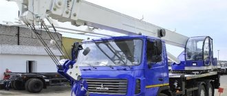
Initially, the MAZ 6303 was created to meet European requirements, which determined its further success. Medium and long-distance work is the main specialty of the multi-functional chassis truck. If the car was created for European roads in accordance with the requirements of international transit transportation TIR, then the safety margin allows it to be successfully used in difficult road conditions. Initially, the MAZ 6303 was designed as a long-haul tractor to work both independently and as part of a road train. Later, log carriers, truck cranes and car lifts, fuel tankers and tank trucks, tow trucks and other equipment were created on its basis. Depending on the superstructure, the MAZ 5303 is used in almost all areas of the national economy, from oil and gas production to agriculture. Even the basic configurations of the car perform excellently both in northern latitudes and in areas with hot climates. There are machines specially adapted for special working conditions.
Modifications
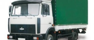
MAZ 6303 can be considered as a universal platform on which, depending on customer requirements, the necessary equipment is installed. Cargo platforms can be open side, curtain or awning type. Dumping platforms, log platforms and cranes with a lifting capacity of up to 25 tons can also be installed. Among the main modifications of the MAZ 6303 that are most widespread are:
- MAZ-630326 is a tractor or log carrier for transporting logs from 2 to 6 meters long as part of a road train. The total weight of the road train can reach 48,000 kg. Wheel formula 6X4;
- MAZ-630168 is a truck with a 6X2 wheel arrangement, designed for transporting goods in the TIR transit transportation system as part of a road train with a total weight of up to 44,000 kg. Complies with TIR requirements.
- MAZ-6317 is an 11-ton cargo all-terrain vehicle with a 6X6 wheel arrangement. Wide-profile all-terrain tires with variable pressure and high ground clearance allow the vehicle to transport cargo over rough terrain as part of a road train with a total weight of up to 55 tons. Often used as an airfield tractor for towing aircraft. Widely used in both military and civilian industries.
Currently, several modifications of platforms are produced with a carrying capacity from 14.5 to 19.5 tons with a 6X4 wheel arrangement. The chassis is equipped with both traditional YaMZ engines and Deutz power plants. The MAZ 6303A5-348 (-349, 351, 352) chassis are intended for the installation of cranes, excavators and concrete mixers. The MAZ 6303A5-348 (-349) configurations are equipped with a central power take-off gearbox (CPG).
Specifications
In the basic version, the MAZ 6303 is a heavy truck with a 6X4 wheel arrangement. The engine is located in the under-cabin space. The car is equipped with two types of cabins:
- Small cabin without berth;
- Large cabin with two berths.
A hydraulic lift is installed to tilt the cab and provide access to the engine systems.
dimensions
- Length – 7600-10230 mm;
- Width – 2500 mm;
- Height – 3130-3200 mm;
- Ground clearance – 260 mm.
Weight parameters
- Gross vehicle weight – 24500 kg;
- Curb weight of the car – 11800 kg;
- The total weight of the road train is 44,000 kg;
- Load capacity – 12700 kg;
- Load distribution at full weight - front axle 6500 kg, rear bogie 18000 kg.
Not available:
| № | Part code | Name | Part Information |
| 53363-3805010 | Dashboard | Quantity per 53363 2) 53366 3) 6303 1 Model 53363 Group Instruments Subgroup Instrument panel Serial part number 010 | Not available |
| 53366-3805010 | Dashboard | Quantity per 53363 2) 53366 3) 6303 1 Model 53366 Group Instruments Subgroup Instrument panel Serial part number 010 | Not available |
| ST-142D | Starter | Quantity per 53363 2) 53366 3) 6303 1 | Not available |
| FG122-3711010 | Headlight | Quantity per 53363 2) 53366 3) 6303 2 Model FG122 Group Electrical equipment Subgroup Lights Serial part number 010 | Not available |
| 2606-3726010 | Front turn signal | Quantity per 53363 2) 53366 3) 6303 2 Model 2606 Group Electrical equipment Subgroup Turn indicators (front) Part number 010 | Not available |
| FG152A-3743010 | Fog lamp | Quantity for 53363 2) 53366 3) 6303 2 Model FG152A Group Electrical equipment Subgroup Fog lights Serial part number 010 | Not available |
| 3812—3710-02-23 | Heated mirror | Quantity per 53363 2) 53366 3) 6303 2 | Not available |
| PF233-3738000EA | Signal lamp | Quantity per 53363 2) 53366 3) 6303 2 Model PF233 Group Electrical equipment Subgroup Light alarm Part serial number 000 Additionally Interchangeable with a part previously released under the same number | Not available |
| 3466212227 | Lamp A24-5TL | Quantity per 53363 2) 53366 3) 6303 2 Group Steering control Subgroup 3466 Serial part number 212 Additionally Not interchangeable with a part previously released under the same number | Not available |
| ME237-3730040E | Electric motor | Quantity per 53363 2) 53366 3) 6303 2 Model ME237 Group Electrical equipment Subgroup Electric motors (electric motor of the heater) or trailer plug socket Serial number of part 040 Additionally Interchangeable with a part released earlier under the same number | Not available |
| S306G/S307G-3721 | Electrical signal kit | Quantity per 53363 2) 53366 3) 6303 1 | Not available |
| RS951A-3726010-UHL | Turn signal switch | Quantity per 53363 2) 53366 3) 6303 1 Model RS951A Group Electrical equipment Subgroup Turn indicators (front) Serial part number 010 Additionally Interchangeable with a part previously released under the same number | Not available |
| AR112-7903000 | Antenna | Quantity per 53363 2) 53366 3) 6303 1 Model AR112 Group Radio equipment Subgroup Antenna Part number 000 | Not available |
| ХГ2-021-030-14 | Radio complete with speakers | Quantity per 53363 2) 53366 3) 6303 1 | Not available |
| PK142—3714000 | Lamp lighting for sleeping places | Quantity per 53363 2) 53366 3) 6303 2 Model PC142. Group Electrical equipment Subgroup Interior lighting lamps Serial part number 000 | Not available |
| 14-3726010E | Side turn signal repeater | Quantity per 53363 2) 53366 3) 6303 2 Model 14 Group Electrical equipment Subgroup Turn indicators (front) Serial part number 010 Additionally Interchangeable with a part previously released under the same number | Not available |
| 11-3714010-50 | Cabin light | Quantity per 53363 2) 53366 3) 6303 2 Model 11 Group Electrical equipment Subgroup Interior lighting lamps Serial part number 010 Additionally Not interchangeable with a part previously released under the same number | Not available |
| 13-5205010 | Windshield wiper 3-brush | Quantity per 53363 2) 53366 3) 6303 2 Model 13 Group Window window Subgroup Wiper and drive Serial part number 010 | Not available |
| 23—3722-01 | Relay fuse box | Quantity per 53363 2) 53366 3) 6303 1 | Not available |
| 64221-3805012 | Dashboard | Quantity per 53363 2) 53366 3) 6303 1 Model 64221 Group Devices Subgroup Instrument panel Serial number of part 012 | Not available |
| 64221-3722014 | Fuse box panel | Quantity per 53363 2) 53366 3) 6303 1 Model 64221 Group Electrical equipment Subgroup Fuses (electrical circuits) Part number 014 | Not available |
| 16—3741 | Pneumatic signal valve | Quantity per 53363 2) 53366 3) 6303 1 | Not available |
| 6303-3805010 | Dashboard | Quantity per 53363 2) 53366 3) 6303 1 Model 6303 Group Instruments Subgroup Instrument panel Serial part number 010 | Not available |
| 40-3709 | Windshield wiper/washer switch | Quantity per 53363 2) 53366 3) 6303 1 | Not available |
| 60-3709 | Turn signal switch | Quantity per 53363 2) 53366 3) 6303 1 | Not available |
| XATE-24 | Fridge | Quantity per 53363 2) 53366 3) 6303 1 | Not available |
| 15-8106 | Heater | Quantity per 53363 2) 53366 3) 6303 1 | Not available |
| ADUI—407511-002 | Fuel level sensor | Quantity per 53363 2) 53366 3) 6303 1 Coated uncoated | Not available |
| 1420—3737 | Ground switch | Quantity per 53363 2) 53366 3) 6303 1 | Not available |
| 6ST-190A | Accumulator battery | Quantity per 53363 2) 53366 3) 6303 2 | Not available |
| 5320—3721500 | Solenoid valve | Quantity per 53363 2) 53366 3) 6303 2 Model 5320. Group Electrical equipment Subgroup Sound signals Part number 500 | Not available |
| MM125B-3810600-E | Pneumatic brake signal switch, locking | Quantity per 53363 2) 53366 3) 6303 2 Model MM125B Group Instruments Subgroup Pressure gauges (oil pressure indicator) Serial part number 600 Additionally Interchangeable with a part previously released under the same number | Not available |
| 25—3708-01 | Starter | Quantity per 53363 2) 53366 3) 6303 1 | Not available |
| VK418A | Limit switch | Quantity per 53363 2) 53366 3) 6303 1 | Not available |
| 2001-3843 | Speedometer sensor | Quantity per 53363 2) 53366 3) 6303 1 | Not available |
| 3202—3731 | Retroreflector | Quantity per 53363 2) 53366 3) 6303 8 | Not available |
| 7402—3716 | Rear right lamp | Quantity per 53363 2) 53366 3) 6303 1 | Not available |
Chassis
The front suspension of the car is leaf spring, on two semi-elliptical springs, with two double-acting hydraulic shock absorbers and a stabilizer bar. The rear suspension is spring-balancer. The steering mechanism is two-stage, with a gear pair, a screw transmission and a built-in distributor. All wheels are equipped with drum-type brake mechanisms. The rear wheel tires are double. The main braking system is of a pneumatic type, with separate drive to the front and rear wheels. The parking brake is pneumatically driven using spring-type energy accumulators on the rear wheels. The auxiliary brake is a compression brake with flaps in the engine exhaust system. The pneumatic drive for trailer (semi-trailer) brakes is two-wire. Depending on the modification, disc wheels can be fitted with 11.00R20 or 12.00R20 tires.
5.3.4 Brake systems of MAZ vehicles
5.3.4 Brake systems of MAZ vehicles
The vehicles are equipped with a service brake with a pneumatic drive. It is the main one, acts on all wheels of the car and consists of a brake mechanism and a pneumatic drive.
The brake mechanism of the service brake (Figure 5.49) includes a brake drum 9, brake pads 5 with linings 7, an expansion fist 3 and an adjusting lever 14. The brake mechanisms of all wheels are interchangeable.
Figure 5.49 – Service brake of a MAZ car
1 – support disk: 2 – spacer sleeve: 3 – expansion fist: 4 – thrust roller; 5 – block: 6 – bushing; 7 – friction lining; 8 – tension spring; 9 – brake drum; 10 – retaining springs; 11 – pad axis; 12 – protective shield; 13 – brake chamber; 14 – adjustment lever; 15 – worm gear: 15 – adjusting worm; 17 – fork; 18 – rod; 19 – diaphragm
The brake drum is bolted to the wheel hub flange. It is cast from gray cast iron. The inner surface of the drum is the friction surface during braking.
The brake pads are stamped, single-rib, rest on an axis 11 installed in the support disk. At the upper ends of the blocks, support rollers are mounted, which are acted upon by the expanding fist 3. The blocks are tightened by two springs 8 and 10, so their ends are always pressed against the support axis 11 and to the surface of the expanding fist.
Friction linings are riveted to the pads. The rivet heads are recessed into the trim. If the distance from the surface of the lining to the rivet head remains less than 1 mm, the linings should be replaced.
The expanding fist is manufactured with the shaft as one unit. The shaft has splines for connection to the adjusting lever. The surface of the expanding fist has a spiral shape, which ensures the movement of the pads from the center to the surface of the drum.
The adjusting lever is mounted on the splined end of the expansion knuckle shaft. A worm and a worm gear are located inside the lever. The worm shaft is secured by a ball lock against arbitrary rotation in the body of the adjusting worm. Rotating the shaft with a key behind the square head leads to rotation of the worm and through it the worm wheel, which turns the expansion cam shaft. As a result, the ends of the pads are moved apart by the required amount. When the worm shaft rotates, clicks of the latch are heard.
The schematic diagram of the pneumatic brake drive of MAZ vehicles is shown in Figure 5.50.
The supply part of the pneumatic brake drive consists of a compressor 1 (Figure 5.50), a moisture separator 2, a pressure regulator 3, a condensation receiver 4, a double safety valve 5 and the pipelines and fittings connecting them.
When the engine is running, compressed air from the compressor enters through the moisture separator 2, the pressure regulator 3 into the condensation receiver 4 and then through the double protective valve 5 into the receivers 8 and 9. At the same time, the compressed air from the compressor through the single protective valve 7 enters the receiver 10, to which the additional consumers: auxiliary brake mechanism drive, clutch booster, etc.
When the pressure in the system reaches 0.8 MPa (8 kgf/cm2), the pressure regulator is activated and further air flow into the system is stopped - the compressor is unloaded into the atmosphere. Simultaneously with the pressure regulator, the moisture separator operates, releasing the condensate accumulated in it into the atmosphere.
The pneumatic brake drive includes the following independent pneumatic circuits:
– brake mechanisms of the front axle wheels;
– brake mechanisms of the wheels of the rear and middle axles;
– parking (spare) brake mechanism;
– semi-trailer brake mechanisms;
– auxiliary brake mechanism and other compressed air consumers.
Figure 5.50 – Diagram of the pneumatic brake drive of MAZ vehicles
1 – compressor; 2 – moisture separator; 3 – pressure regulator; 4 – condensation receiver; 5 – double safety valve; 6 – control valve; 7 – single safety valve; 8 – front circuit receiver; 9 – rear circuit receivers; 10 – receivers for consumers; 11 – engine brake control valve; 12 – fuel shut-off cylinder; 13 – pneumatic cylinder for controlling the auxiliary brake; 14 – check valve; 15 – valve for controlling the semi-trailer brakes using a two-wire circuit; 16 – valve for controlling the brakes of a semi-trailer using a single-wire circuit; 17 – parking brake control valve; 18 – brake valve; 19, 19a – accelerator valve; 20 – brake force regulator; 21 – brake chamber with spring energy accumulator; 22 – front brake chamber; 23 – two-line valve; 24 – disconnect valve; 25 – connecting head; 26 – pneumatic outlet for a single-wire semi-trailer circuit; 27 – switch (sensor); 28 – brake signal switch; 29 – sensor; 30 – condensate drain valve; 31 – anti-freeze fuse; A – output to consumers
All air receivers are equipped with condensate drain valves 30. In addition, the pneumatic system includes pneumoelectric sensors 27, connected to the corresponding warning lights on the instrument panel, which turn on when the pressure in a particular circuit decreases below 0.56 MPa (5.6 kgf/ cm2), as well as sensors 29 associated with pressure gauges installed on the instrument panel.
The pneumatic drive of the service brakes works as follows. When you press the brake pedal, the brake valve 18 is activated. Compressed air from the receiver 8 through the lower section of the valve enters the brake chambers 22, which activate the brake mechanisms of the front axle wheels. From the upper section of the brake valve, through the brake force regulator 20, air is supplied to the control line of the accelerator valve 19, as a result of which the latter passes compressed air from the receivers 9 into the brake chambers of the wheels of the rear and middle axles.
At the same time, through the two-line valve 23, air enters the control line of the accelerator valve 19a, which passes compressed air from the receiver into the cavities of the energy accumulators 21, eliminating the possible double impact on the wheel brake mechanisms (from the working and parking systems).
The brake valve, brake force regulator and accelerator valve have a follower device, that is, compressed air enters the brake chambers, the pressure of which depends on the amount of movement of the brake pedal. In addition, the brake force regulator takes into account the load on the rear suspension and, depending on it, passes a certain pressure into the control cavity of the accelerator valve 19. When the rear suspension is fully loaded, the brake chambers receive full pressure, determined by the brake valve 18. When releasing the brakes, air from the front brakes chambers, the brake force regulator and the control cavity of the accelerator valve 19 exits into the atmosphere through the brake valve, and from the rear brake chambers through the accelerator valve 19a.
During braking, compressed air from the drive lines of the front and rear brake mechanisms enters the brake control valve 15 of a semi-trailer with a two-wire drive, as a result of which the valve is activated and air from receivers 8 and 9 through single protective valves 7 and check valve 14 enters the lines of the semi-trailer.
When a tractor is coupled to a semi-trailer with a single-line brake drive, compressed air flows through the brake control valve 16 of a semi-trailer with a single-line drive and the connecting head to the air distributor of the semi-trailer and into its air receiver.
When braking, air is released from the connecting line through valve 16 and the semi-trailer is braked.
When coupling a tractor with a semi-trailer with a two-wire brake drive, connecting heads 25 of the power and control lines are used.
The pneumatic drive of the parking and emergency brakes operates as follows. Compressed air from receivers 8 and 9 through single safety valves 7 and check valve 14 is supplied to parking brake control valve 17, from which it enters the control line of accelerator valve 19a through a two-line valve 23, as a result of which the latter passes compressed air from receivers 8 and 9 into the cylinders of energy accumulators of brake chambers 21.
When braking with the parking brake (the valve handle 17 is installed in the rear fixed position), air from the control line of the accelerator valve 19a escapes into the atmosphere. In this case, the air from the cylinders of the energy accumulators of the brake chambers 21 escapes into the atmosphere through the atmospheric outlet of the accelerator valve. The springs, unclamping, activate the brake mechanisms of the rear axle.
At the same time, valve 17 turns on valve 15 for controlling the brakes of a semi-trailer with a two-wire drive, thereby ensuring braking of the semi-trailer. In the event of an emergency drop in pressure in the parking brake drive circuit, the spring energy accumulators are activated and the vehicle is braked.
In this case, to release the car, it is necessary to unscrew screws 10 (Figure 5.44) on all brake chambers 21 (Figure 5.50).
The parking brake control valve has a tracking device that allows you to slow down the vehicle (by the backup brake system) with an intensity depending on the position of the valve handle.
The pneumatic drive of the auxiliary brake system operates as follows. When you press the auxiliary brake control valve 11, compressed air enters the auxiliary brake control pneumatic cylinder 13. The cylinder rod, connected to the auxiliary brake flap lever, turns the flap and it closes the exhaust pipe of the muffler. At the same time, compressed air enters cylinder 12, the rod of which moves the engine stop bracket, thereby stopping the fuel supply.
The purpose and design of pneumatic brake drive devices are considered in the brake system of KamAZ vehicles.
Features and operation
Despite the fact that the MAZ 6303 cabin was developed a long time ago and is inferior in design to many Western competitors, overall it turned out to be successful. Experts note low noise and vibration levels, good visibility from all sides. Not only the driver's seat, but also the passenger seat has air suspension. In conditions of low temperatures, a comfortable stay in the cabin is ensured by the main and additional heating systems. However, the location of the heater tap under the cabin does not add comfort in severe frosts. Drivers also complain about the air filter cover on studs with nuts (instead of latches), which makes it difficult to quickly replace the filter element. Claims are often made about the location of the cabin hydraulic lift in a place unprotected from dirt. However, despite minor shortcomings, reviews of the car among motorists are mostly positive. In the basic configuration, the MAZ 6303 is equipped with:
- Spoiler and protective device at the rear;
- Backlash-free coupling;
- Electro-pneumatic outlets for the trailer;
- Seat belts;
- Engine pre-heater;
- ABS system.
The engines of the Yaroslavl Mechanical Plant of the 238th series installed on the MAZ 6303 do not cause any particular complaints. Depending on the intended purpose, power plants with a capacity of 170 to 400 hp can be installed. In general, the car is reliable, easy to maintain and repair, and is familiar to domestic drivers. There are no problems with the availability of consumables and spare parts, the price of which is significantly lower than for European and American analogues of the MAZ 6303.
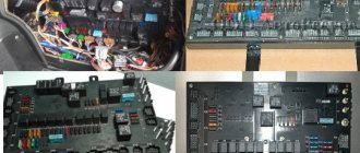
Electrical diagram of a MAZ car
Two variants of electrical circuits for MAZ cars. All diagrams are presented in the form of small copies - to enlarge, click on the image and download to your computer.MAZ electrical circuit - option 1
1 fg1119-3711000-in-tumular fog 3 mm350b-3810000-g sensor of the oil and air pressure indicator MM-350B 4 SK-RRP127-3702000 relay-regulator assembly 5 PF101-3712000-in-fabric assembly 6,500-372432-g of the beam wires of the right sidelight 7 FG-122-3711000-V Headlight 8 PS5-3723000 Five-terminal connecting panel 9 PZhD400-1015410-B Heater control panel 10 500-3724045-B2 Wire bundle between the headlights 11 SL108-5205000-G Windshield wiper Itel electric SL-108 12 SK101-3721000 Two-tone audio signal assembly 13 500-3724086-B Wire bundle for engine heater 14 500A-3724030 Wire bundle along the spar 14 503A-3724030 Wire bundle along the spar 14 504A-3724030 Wire bundle along the spar Gerona 15 G270A-3701000-G Generator in assembly 15 SK-ST103-3708000 Starter assembly 16 SK-P39-3710000 Foot light switch 18 500-3724058-B Starter wire bundle 20 500-3724064-G Cabin and engine connection wire with ground 21 PS12-3723000 Twelve-terminal connecting panel 22 ME233 -3730000-G Heater electric motor 23 51-3723100 Wire coupling assembly 24 500-3724080-B1 Heater electric motor wire 25 PR102-3722000-B Fuse block with fuse-links assembled 26 PR102-3722000-B Fuse block with fuse with inserts 27 RS401 -3726000-G Turn signal breaker RS-401 28 500-3724010-Zh1 Main wire bundle 29 500-3724062-E Wire from batteries to starter 30 KP-118-3801000-G Instrument panel assembly 31 UK-143 Water temperature gauge 32 UK-144 Air and oil pressure indicator 33 SP-134 Speedometer 34 PP127-3713000-B Lamp sockets 35 UB-125 Fuel level indicator 36 PD20-3803000-P Turn signal indicator light 37 SK-VK26-3720000-A2 Instrument switch , windshield wipers and fog lights 38 SK-P20-3710000-A2 Switch for lampshades, heater and fuel tanks 39 PP2-3713000 Holder for low beam warning lamp. L28x1 lamp 40 500-3724073-B1 Wire from the instrument switch to the instruments 41 G-P38-3709000 Lighting switch 43 AP-109 Ammeter 44 500-3724050-G1 Wire bundle for lampshades 45 504-3724022-V Fuel level indicator wire bundle 45 504B- 3724023-B1 Fuel level indicator wire 47 500-3721080-B Signal contact device assembly 48 SK-P109-3709000-B2 Turn signal switch 49 ME302V-3730000-G Speedometer sensor 50 6TB.266.003 Plug socket for portable lamp 5 1 SK-VK318- 3704000-B Battery ground switch 52 500-3724052-B Ground wire for portable lamp socket. . 53 500-3724039-B Power cable for a portable lamp socket 54 500-3724057-D Battery jumper 55 501-8104210 Driver blower fan 56 PK201-3714010-A Cabin lighting 57 PS4-3723000-A2 Two-terminal connecting panel 58 SK-BM127- 3806600-A Fuel level indicator sensor 59 SK-VK13-3720000-B Stop signal switch 60 FP101-3716000-G Right rear light assembly 61 PS1-3723000-A2 Three-terminal connecting panel 61 PS2-3723000-A2 Four-terminal panel connecting 62 500-3724031-B1 Wire bundle of the left rear light and trailer socket 62 503A-3724032 Wire bundle of the rear lights 63 PS300-3723100 Trailer socket 64 FP101-3716000-B Left rear light assembly 65 PK201-3714010 -A Engine light 66 FYu3 -552-030 Rechargeable battery 6TST-165EMS 67 500-3724069-V Wire from the battery to the main switch 68 SK-TM100-3808000-G Water temperature indicator sensor TM-100 69 SK-RS512-3721000 Signal relay 73 500-3724058- G Bundle of starter wires (when installing a pre-heater) 75 UP101-3726000-B Side turn signal repeater 76 500-3724160 Bundle of wires for the engine assembly 77 500-3724032-G1 Bundle of wires for the right rear light 78 500-3724041-A1 Bundle of wires for the fog lights headlights
MAZ electrical circuit - option 2
Al - Fuse and relay block, A3 - Windshield wiper breaker, A6 - Turn indicator breaker, A7 - Radio, A8 - Range locking relay, BAI, BA2 - Loudspeaker, VK - Temperature sensor, VR1.VR2 - Air pressure sensor, VRZ - Sensor oil pressure, BP4.BP5 - Emergency air pressure sensor, BPI0 - Emergency oil pressure sensor, BV2 - Speedometer sensor, BV3 - Speed sensor, EKZ, EK4 - EFU spark plug, E1, E2 - Headlight, EZ, E4 - Fog light, E5,E6 - Front lamp, E7 - Lantern, E8 - License plate lamp, E9...E11 - Road train sign lamp, EI2 - Underbody lamp, E13, E14 - Side direction indicator, EI5.EI6 - Position lamp, E17, E18 - Rear lamp, E20 - Reversing lamp, E23.E24 - Cabin lamp, E25 - Engine lamp, E26 - Headlight - spotlight, E28, E27 - Bed lamp, EK1, E2 - Shelving lamp, EZO - Mirror heater, EL1…EL6 — Instrument backlight lamp, FU1 — Fuse 60 A, FU2 — Fuse 30 A, FU3—FU9 — Fuse 8 A, FU11 — Fuse 16 A, G — Generator, GBl, GB2 — Battery 6ST I90A, ON 1 — Set of electrical signals, HA2 - Pneumatic signal, KK1 - Additional resistance, KK2 - Parking brake warning lamp breaker, K1 - Starter relay, Ml - Starter, M2, MZ - Heater electric motor, M4 - Windshield wiper motor, M8 - Washer motor, RR - Instrument cluster, P2 - Tachometer, PS - Speedometer, RP - Backlight rheostat, XSl - Main socket, XS3 - Socket, XS4 - Socket for portable lamp in the cabin, XS5, XS6 - Socket, WA - Antenna, SA1 - Starter switch, SA2 - Windshield wiper switch, SA3 — Main light switch, SA4 — Turn signal switch, SA5 — Heater switch, SA7 — Flashlight switch, SA8 — Lamp switch, SB1, SB3 — Push-button switch, SB4 — Hazard switch, SA9 — Hydraulic extraction valve switch, Push-button backlit switches: SB5 - Fog lights, SB8 - Neutral switch, SB9 - Engine light, SB11 - Finder headlight, SB12 - Cross-axle differential, SB13 - Center differential, SB 14 - Road train lights, SB 15 - Heated mirrors, SB20 - Rack lighting, SK - Emergency temperature sensor, SLI - Fuel level sensor, SP1.SP6 - Stop signal switch, SP7 - Switch, SQ1, SQ2 - Switch.
Warning lamps: HG1 - Warning lamp block, HG4 - Tractor turns, HG5 - Trailer turns, HG7 - ECU systems, HG8 - High beam, HG9 - Divider switches, HG10 - Interaxle locking, HG11 - Interwheel locks, HG12 - Neutral switches.
CAR ELECTRONICS REPAIR
Engine
Most MAZ 6303 are equipped with a YaMZ-6582.10 engine.
Main settings
- Type - four-stroke, with compression ignition, direct fuel injection, with turbocharging with intercooling of charge air;
- Number and arrangement of cylinders – 8, V-shaped;
- Working volume – 14.86 l;
- Compression ratio – 17.5;
- Rated power – 330 hp. (242.6 kW);
- Rated rotation speed – 1900 rpm;
- Maximum torque at 1100-1300 rpm – 1520 Nm (155 kgf.m);
- Minimum specific fuel consumption – 200 g/kWh;
- Engine weight – 1645 kg.
The engine complies with environmental safety standards according to Euro-3 standards.