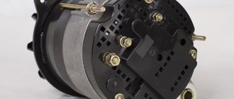
Design and operating principle
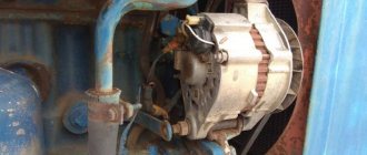
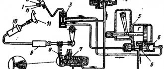
First you need to figure out where the MTZ generator is located. It is located on the side of the crankcase and is mounted on a rotating base. At the top point, the generator belt is fixed, which transmits torque.
A strap is also needed to rotate the coolant container. If it breaks, the operation of all systems automatically stops.
At the ends of the generator cover there are holes for air injection.
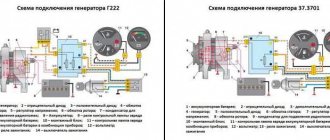
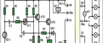
The diagram from the service manual looks like this:
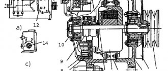
The heart of the unit is the stator. Inside it there is a core made of stamped plates with a winding.
The winding forms phases connected in series in a delta circuit. The stator contains a bearing with a fixed shaft. It is pressed into a package of stamped plates. Supports are built into the removable covers. The shaft toe is equipped with an impeller-fan for active cooling.
The unit is equipped with excitation coils. They are supplied with current from the battery, which puts the system into operation.
If there is no battery in the equipment, then you can switch the generator to parallel excitation mode. In this case it will work independently.
By the way, for this reason the generator is called self-exciting.
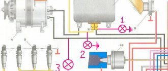
So, the principle of operation is as follows:
- First the rotor starts. With its oscillations, it creates a magnetic field that affects the stator.
- Electromagnetic pulses create a three-phase alternating current in the stator, which is subsequently inverted into direct current. In some variations, it is necessary to connect an additional relay.
Generator with self-excitation and demagnetizing winding
The main difference between this type of generator is that the magnetizing excitation winding is powered not from an external source, but from the generator itself. Therefore they are called self-excited generators.
Schematic diagram and design of the magnetic system of a four-pole self-excited generator.
In collector generators, in addition to the main poles and windings, there are 2 additional poles, on which one turn of an additional series winding is placed. This is necessary to compensate for the magnetic flux of the armature reaction and maintain the position of the electrical neutral of the machine when the load changes.
For normal operation of a self-excited generator, it is necessary that the voltage supplied to the magnetizing winding does not change during the welding process, i.e. did not depend on the welding mode. For this purpose, a third additional brush z , which is located between the two main brushes a and b . When analyzing the operation of this generator, it is necessary to take into account the magnetic flux Fya created by the welding current flowing through the turns of the armature winding, the so-called armature reaction flux.
Picture of the distribution of magnetic fluxes under the polarity pole N of a four-pole generator
It is clear from the figure that under one half of the poles the force lines of the armature field enhance the magnetizing flux Fn. and under the other, they weaken it. In general, the magnetizing effect of the armature reaction flux is compensated by its demagnetizing effect. Therefore, when analyzing the operation of generators with independent excitation, the influence of the armature reaction flux was not taken into account.
In self-excited generators, the parameters of the armature winding and the demagnetizing winding are selected so that under one half of the poles (between brushes b - z ) the magnetic flux of the demagnetizing winding is compensated by the flux of the armature reaction. As a result, the voltage on the brushes bz will be determined by only half of the magnetic flux of the magnetizing winding.
Thus, the voltage supplying the magnetizing winding turns out to be independent of the welding current. The falling characteristic of the generator is ensured due to the demagnetizing effect of the demagnetizing winding, which manifests itself under the second half of the poles.
This allows us to conclude that the mode control in self-excited collector generators is the same. as in generators with independent excitation.
The peculiarity of self-excited generators is that they can only be started when the armature rotates in one direction, indicated by the arrow on the stator end cover.
This is due to the fact that the initial excitation of the generator when it starts is due to the residual magnetization of the poles. When the armature rotates in the opposite direction, a current in the opposite direction will flow in the excitation winding, which, with its growing magnetic field, at some point in time compensates for the residual magnetization of the poles, i.e. the total magnetic flux under the poles will become zero. In this case, to excite the generator, it is necessary to temporarily connect the magnetizing winding to an independent direct current source.
Unit ADD-303 with collector generator
VALVE WELDING GENERATORS
They appeared in the mid-70s of the 20th century after the development of the production of power silicon valves. In these generators, the function of current rectification, instead of a collector, is performed by a semiconductor rectifier, to which the alternating voltage of the generator is supplied.
Welding units use generators of three types of alternating current generator designs: inductor, synchronous and asynchronous
Alternator designs:
a - inductor, b - synchronous, c - asynchronous
In Russia, welding units are produced with inductor generators with self-excitation, independent excitation and mixed excitation.
Scheme of a self-excited valve generator
Circuits of single-phase and three-phase valve generators with independent excitation
Constructive diagram and connection of parameters of an inductor generator
In an inductor generator, the stationary excitation winding is powered by direct current, but the magnetic flux it creates is variable. It is maximum when the teeth of the rotor and stator coincide, when the magnetic resistance along the flow path is minimal, and is minimal when the cavities of the rotor and stator coincide.
Hence. The emf induced by this flow is also variable. Three working windings are located on the stator with a shift of 120°, so a three-phase alternating voltage is formed at the generator output. The falling characteristic of the generator is obtained due to the high inductive reactance of the generator itself. The rheostat in the excitation circuit serves to smoothly regulate the welding current.
The absence of sliding contacts (between the brushes and the commutator) makes this generator more reliable in operation. In addition, it has a higher efficiency, smaller weight and dimensions than a collector generator. Dynamic characteristics can also be significantly improved.
Schematic diagram of a valve generator type GD-312 with self-excitation
VSKh generator GD-312
To ensure no-load operation, the excitation winding is powered from a voltage transformer, and to power it in short-circuit mode, from a current transformer. In load mode - welding - a mixed control signal proportional to part of the output voltage and proportional to the current is supplied to the excitation winding.
Valve generators are manufactured under the GD-312 brand and are used for manual welding of metals as part of ADB-type units
Connection diagrams for the windings of a three-phase inductor generator
Valve generator GD-4006
Schematic diagram of the generator GD-4006
VSKh generator GD-4006
In Russia, several designs of multi-station units are produced with the number of posts from 2 to 4.
The market offers universal units for several welding methods or welding and plasma cutting. In particular, the ADDU-4001PR unit
Design of the ADDU-4001PR unit
The formation of artificial VSCs of the ADDU-4001PR unit is ensured by a thyristor power unit with microprocessor control.
Wider technological capabilities are provided by the use of inverter power units in units, such as in the Vantage500 unit.
Inverter power supplies.
Inverting in converter technology is the conversion of direct voltage into alternating voltage.
Inverters of welding power sources are made using power thyristors and transistors. Thyristor inverters are inferior to transistor inverters in terms of maximum conversion frequency (by an order of magnitude) and, accordingly, in terms of weight and size indicators. Therefore, in the production of welding IP they are now almost completely replaced by transistor inverters.
Let's consider one of the widely used transistor inversion circuits.
Rectifier V1 converts the mains voltage (~380V, 50Hz) into constant voltage, the unevenness of which is smoothed out by the L1-C1 filter. An inverter using transistors VT1-VT2 converts direct voltage into high-frequency alternating voltage (~ 50 kHz). Next, the voltage (~ 380 V) is lowered by transformer T to welding voltage (80 V), rectified by rectifier V2 and smoothed by filter L2-C2. Since high-frequency alternating current is transformed, the transformer is made not with an iron core, but with a ferrite core, which reduces its weight by about 10 times. Since the frequency of the transformed current is high, the duration of transient processes is reduced from n*10-2 s to 10-3 s or less.
Currently, the bulk of inverter equipment for welding production consists of power supplies with high-frequency transformers, since electrical safety conditions during manual welding and semi-automatic hose welding, as well as during plasma cutting, require galvanic isolation of the secondary circuit from the power network.
Regulating the mode (obtaining a falling current-voltage characteristic and adjusting the secondary voltage on the hard characteristic) is usually carried out by changing the frequency.
Oscillograms when regulating voltage by changing the amplitude (a), frequency (b) and width (c) of pulses
To obtain a falling characteristic, current feedback is introduced: as it increases, the frequency automatically decreases, which entails a decrease in the output voltage. To stabilize the output voltage at rigid characteristics, voltage feedback is introduced.
External characteristics of rectifiers with inverter
In the 80s and until the mid-90s, inverter rectifiers were produced with low power (up to 160 A), for installation work and for domestic needs. In the mid-90s, a new generation of so-called field-effect transistors appeared that could withstand high currents. This made it possible to begin producing industrial inverters for currents of 300-500 A.
Modern switching devices: MOS transistor (a); bipolar transistor with insulated gate (b); transistor-diode module - chopper (c); power module with optimized control and comprehensive internal protection (d)
In welding power supplies with power transistors, several inversion circuits are used.
Single-ended converter with direct diode connection
Single-ended converter with reverse diode connection
Push-pull bridge converter
Push-pull half-bridge converter
Resonant push-pull bridge converter
Real power circuits of inverter power supplies may differ significantly from standard ones.
Rectifier DS.250.33
Straightener Caddy Arc 150
Rectifier InvertecV350-PRO
Rectifier Forsazh-160
Advantages of inverter power supply:
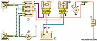
Generator connection diagram
So, every tractor driver needs a wiring diagram for a car generator in order to put it into operation directly “in the field”.
Process description
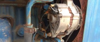
Connecting the MTZ 80 generator is a simple procedure. It is done in several stages:
- The generator is bolted to the side of the engine.
- Then the belt is tensioned and finally secured with a bolt.
- Then you need to connect the electrical. It is attached using the standard “terminal-bolt” method. Here is the generator wiring diagram.
How to check the generator at MTZ? You need to turn the ignition key. If the red light comes on, it means an error has been made. She talks about insufficient charge. You need to check the connection diagram again.
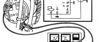
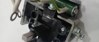
Winding check
The generator on the MTZ 82 still does not start; perhaps the problem is not in the connection, but in the winding itself. Then you will need to diagnose the system.
To do this, you need to disconnect the generator from the engine and fully charge the battery. So, you need to throw a minus on contact M, and a plus on W.
If the coil is working properly, the light bulb will burn very dimly. Bright light indicates serious problems.
Additional tests may also be needed:
- The minus is on M, and the plus is on B. It is necessary to include an indicator light in the circuit. If all is well, it will not burn. In the event of a breakdown of the diode or the positive terminal on the housing, the indication will be noticeable.
- Minus for any AC voltage contact, and plus for the B-block. The result, as before, is determined by the light bulb.
- Positive for M, and negative for variable contacts. If the lamp is on, it means there is a breakdown in the diode.
It will also not be superfluous to make sure that the light bulb itself is working. Sometimes it doesn't light because it's broken.
Using a generator from Eurokamaz
Using a generator from Eurokamaz is possible with minor changes. The design of such a device is very close to that of a tractor, but has a higher voltage and current. The procedure for upgrading the unit is the same: the windings are rewound and powerful magnets are installed that create an alternating magnetic field.
The initial operating speed of the rotor is too high, so an increase in the number of turns on the windings will be required to respond to low speeds. After winding, it is recommended to connect the generator to a rotation source (most often an electric drill is used) and measure the amount of current generated. Such a preliminary measurement will allow us to obtain certain information about the parameters of the resulting device and, if necessary, make some changes to the design.
Maintenance of devices at MTZ
To ensure that the controls and the generator itself do not fail, it is better to carry out regular maintenance.
First of all, it is necessary to regularly remove the oil and dust that settle under the lid. It is better to blow off the dust with a compressor, but ordinary rags will do. If dirt has clogged the cracks, disassembly and wiping will be necessary. You need to do it with the same rag soaked in gasoline. You should not use cotton wool or synthetics for cleaning.
You need to regularly inspect the terminals for oxides. As soon as they appear, they must be removed mechanically with sandpaper or a file. You should act carefully, just to remove the oxide film. You can also lubricate the contacts with copper or silicone grease.
Inspect the impeller and pulleys periodically. Any cracks or chips indicate an imminent major overhaul. It is better to replace them immediately to avoid emergency situations. Likewise, it is recommended to check the belt tension.
After connecting the generator and the engine has been started, look at the warning light. It should go out immediately. On some MTZ tractors, idle flashing is normal if the rotation has not reached 1.4 thousand revolutions.
Magneto wind generator
A magneto has a slightly different design than a tractor generator. It is equipped with two windings, low and high voltage. The second winding is not needed, since the voltage that it is capable of delivering is not suitable for a windmill. A slight increase in wind speed will cause a sharp surge in voltage, which can damage consumers or intermediate equipment. Therefore, the secondary winding is dismantled, and the primary winding is rewound to high power so that the device is able to produce results at low speeds.
In addition, you will need to exclude the participation of the breaker. There are two methods here:
- physical dismantling of the breaker cam;
- installation of a shorting jumper between the contacts, ensuring a permanent connection.
Frequent problems and their diagnosis
1 So, the control light does not go out, what should you do? Do not panic and immediately check the belt tension. If it is in order, then you need to check the contacts for oxides. If performance is not restored after cleaning, you need to check the output voltage. It should not be lower than 12.5 volts.
2 If you hear extraneous noise and knocking during operation, the problem is the loosening of the pulley fixing nut. However, bearing failure is also possible. Diagnosed by routine disassembly. The bearing will noticeably crunch when worn and will need to be replaced. The nut can be lubricated with thread sealant and tightened more tightly.
The main thing is that the fit on the pulley is not disturbed. You can notice a broken seat by the free movement of the nut. In this case, it needs to be replaced.
3 Under no circumstances should the bearing be knocked out. The shaft can be damaged, and this is a major repair. A special puller is required.
Otherwise, other generator breakdowns rarely occur on MTZ tractors.
DIY tractor generator repair
Like any mechanism, the generator and its components tend to wear out and break. A malfunction can be indicated by an ammeter located on the dashboard and showing the amount of current, which depends on the condition of the battery.
When the battery is charged, after the engine starts, the needle on the device deviates to charge, but not for long, because the current decreases to 1-2 A. Before looking for a breakdown, you should check the battery charge, the accuracy and serviceability of the ammeter. This can be easily checked by turning on the headlights while the engine is not running. The device should show discharge.
Diagnosis of tractor generator failure
If the ammeter does not show a charge when the engine is running, then there may be a breakdown of the generator or relay regulator. At low engine speeds, disconnect the wires from the terminals, connect them to each other and increase the speed. If the generator is working properly, the current will increase.
This means the problem is in the Tractor regulator relay. It needs to be adjusted. The causes of malfunction of the generator itself may be the commutator - its contamination, wear, as well as dirty or worn brushes. If, after cleaning these parts, stable operation is not ensured, then you need to look for breaks or short circuits in the circuit or windings; wire oxidation; belt tension; broken rectifier diodes. If noise is heard when the generator is operating, there may be a foreign object in the device, the fan or bearings may be faulty and require replacement.
Once a malfunction is detected, the generator should be disassembled.
Disassembling and cleaning the generator
Wipe parts containing wires with a rag soaked in gasoline, blow off and dry. Rinse the rest in kerosene or a special solution. If the problem is in the rotor, then the following problems may occur: magnetic properties are lost, the magnet is cracked, the rotor is bent.
If it is necessary to replace the pulley, the washer is bent, the nut is unscrewed and the pulley itself is removed using a puller. If necessary, change and reassemble in the reverse order.
When changing the rectifier unit, the screws are unscrewed, the cover is removed, and the wires are disconnected from the terminal. Next, the field winding wire and stator leads are removed, the washers and the rectifier itself are twisted off the latter, after which it is replaced. The rectifier unit is also removed when replacing the bearing and stator. In addition, the nut is unscrewed, the impeller is removed, and the bolts are removed. Next, a bushing is placed and between it and the screw there is a metal plate. Then the back cover is removed and both the stator and the bearing are changed directly.
After all replacements, the generator is assembled in the reverse order.