Hi all. The other day I asked questions here on the blog. I didn’t know the specifics. I decided to collect the information in one pile and systematize it. I hope that the information will be useful to those who are not in the know. So here we go:
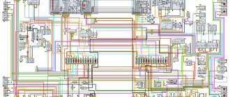
New UAZ Hunter models are equipped with an electronic speedometer; they are made at the Avtopribor plant in the city of Vladimir. The principle of operation is simple, the speedometer measures and converts the speed sensor shaft speed into speed readings, and the number of shaft revolutions into readings of the distance traveled by the car.
The first modifications of the UAZ Hunter were equipped with AP 20.3802 speedometers produced by the RAR plant, Riga. The speedometer of the Vladimir plant for UAZs is identical in size and connection diagram to the Riga speedometer.
If everything is clear with the high beam indication, then I will dwell on the conversion factor in more detail. A little from the history and principle of operation of UAZ mechanical speedometers (GAZ, IZH, etc.): The most important parameter of the odometer of a mechanical speedometer is the gear ratio of its internal gearbox. According to the international standard, this value should be equal to 1000, that is, for any one unit of the distance traveled there are a thousand revolutions: 1000 revolutions per mile according to the English system of measures, 1000 revolutions per kilometer according to the metric system of measures.
But on the mechanical speedometers that were originally installed on UAZ/GAZ cars of the entire model range, the number of revolutions of their flexible drive shaft corresponding to one kilometer of run was 624 revolutions, that is, it makes 1000 revolutions not for one kilometer of travel, but for one land mile - 1609 meters .
Now about the speed sensors and conversion factors that are indicated in the characteristics of the speedometers: If the transfer case is of an old vintage, then with a high degree of probability it is necessary to install a 10-pulse speed sensor, because the speedometer drive produces 624 revolutions/kilometer, which at the output of the sensor is - 624x6 = 3744 pulses. If the transfer case is of a later production year, then with a high degree of probability it is necessary to install a 6-pulse speed sensor, because the speedometer drive produces 1000 revolutions/kilometer, which at the output of the sensor is 1000x6 = 6000 pulses.
There is one more nuance that is worth paying attention to, this is the thread on the speed sensors. On UAZs and IZH-ODAs, the thread for the installation location is M22. To avoid making adapters, a sensor marked 345.3843/497.3843 will fit in the standard location.
Based on the above, it is not difficult to understand that if the parameters of the speedometer conversion factor and speed sensor pulses do not match, the readings will differ. For example, when driving at 60 km/h, the device will show about 100 km/h. Or vice versa, at a speed of 60 km/h, the readings will be equal to 37 km/h.
When purchasing components to replace the speedometer with an electronic one, you need to buy a block, female block KG-602207.
How to connect: When installing an electronic speedometer Autodevice instead of a mechanical one, you need to install a speed sensor on the transfer case instead of a flexible shaft on the speedometer drive, connect the contacts as follows: – pin 1 of the speed sensor with pin 7 of the speedometer – pin 2 of the speed sensor with pin 4 of the speedometer – pin 3 of the sensor speed with speedometer pin 1
Did you like the article? Follow our channel for new ideas of useful car tips. Subscribe to us in Yandex.Zen. Subscribe.
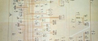
It would not be an exaggeration to call the legendary model “452” the ancestor of a whole family of multi-purpose utility vehicles under the UAZ brand. This is true, and experts are well aware that the wiring diagram of the UAZ 3962, components and transmissions of the model 3904, as well as other modifications, are unified with the “452”.
All world manufacturers of passenger cars and utility vehicles are developing in a similar way:
- A successful design serves as the basis for a whole family of cars;
- Constant refinement and modernization allows us to update the model range;
- Unification of parts and components reduces the cost of creating new cars.
For reference: When car owners communicate with each other about the “civilian” version of a particular UAZ unit, this is true. Initially, “452” was created by order of the Ministry of Defense as a vehicle accompanying tank columns on the march. And for use on public roads, the car was modernized.
electrical wiring UAZ diagram: features of modifications with multifunctional I liked it
management article? Follow new ideas for useful auto tips in our channel. Subscribe to Yandex in us.Zene. Subscribe.
All world manufacturers of passenger cars and utility vehicles are developing in a similar way:
- the Udachnaya design serves as the basis for an entire family of cars;
- Constant refinement and modernization allows the model range to be updated;
- The unification of parts and components reduces the costs of creating new cars.
Unit repair and maintenance
Signals for repairs can be:
- Oil leak.
- Increased noise and vibration.
- Difficulty switching from one position to another.
- Spontaneous loss of the switched on operating mode.
Although often, to fix problems, it is enough to just adjust the fasteners or lubricate problem areas and points. If this does not help, the car must be driven into an inspection pit or overpass, after which technological operations must be carried out in strict sequence.
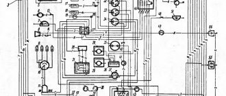
Features of modification with multifunctional Variations
control with the car body was not too strongly influenced by the technical equipment. But when changes were made to the governing bodies, the following were modernized:
- In-cabin wiring for UAZ;
- Steering column control unit for external and turning lighting;
- Control unit for electric windshield wipers on the instrument panel.
Reason For reference
modernization: according to pan-European safety requirements, the activation of light and sound devices while the driver is moving the vehicle must not remove the steering wheel from his hand. The wiring diagram for the VAZ 2112 and other models of the Tolyatti Automobile Plant is built on this principle.
On cars of the UAZ family, the windshield wiper control unit was located on the panel because. And the devices did not meet safety requirements, then on all subsequent modifications:
- it was replaced with a more multifunctional modern unit located directly on the steering wheel;
- wheel, install a new instrument panel.
modernization Independent
Cars of new releases already have a multifunctional control unit in their base. But the owners of early editions can re-equip the car with their own hands to meet modern safety requirements.
For this you will need:
The operating algorithm will be Disabled:
- next battery;
- We remove the control unit from the panel;
- We disconnect the wires, checking their factory compliance with the diagram in Fig. 1;
- We remove the standard columns from the steering wheel switches.
To remodel, you will need to purchase several new parts:
- Block of steering column multifunction switches from the UAZ 390995 model;
- for the windshield wiper circuit relay (the VAZ model is best suited, as is the wiring 2112, the relay connecting and the switch block);
- There are 3 contact blocks (one 8-pin for the side of the steering column switches and two 6-pin for the relay and standard adapter).
Advice: a good help for remaking any electrical circuit can be the video on our website, which is shared by car owners who service their cars themselves.
Let's start installation:
- standard Replace the connector with a new one;
- We cut the wire (indicated by a red cross on 4x4.2);
- We connect its ends to 31V and to the S contact of the windshield wiper relay;
- contact with Connect 15 windshield wiper relay wire 5-2;
- Contact J connects the relay to the 2nd contact of the steering column switch;
- We connect the relay ground to pin 13;
- We connect the new contact block with an adapter cable;
- We connect it to the block that was previously connected to the standard switch on the instrument panel;
- contacts We close the windshield washer electric motor to switches 6 and 7 contacts;
- On the relay, connect pin 86 to pin 6 of the steering column switch.
Car enthusiasts improved the modification scheme proposed by the manufacturer by introducing some pictures into it (for changes.3):
- A variable resistor R=was introduced into the circuit, thanks to which the pause value in the intermittent operation mode of the windshield wipers can be smoothly changed from 4 s to 15 s;
- resistor Connection should be made in such a way that the operating mode starts from the moment the motor brushes stop.
Conclusions: cars of the UAZ family are not unitary, only multi-purpose SUVs, but also easy-to-maintain vehicles. Almost any car owner, armed with knowledge and colored electrical diagrams, is capable of not only restoring a unit that has failed, but also carrying out useful modernization of its and the car’s individual elements.
Platform for conveyor models
The “Loaf”, which became famous, thanks to its all-metal body, the “452” model served as a platform for the creation of an entire line of vehicles:
- UAZ 2206 – a minibus designed for 11 people;
- UAZ 3962 – vehicle for emergency medical services;
- UAZ 396255 - a civilian modification of an ambulance for the needs of rural areas;
- UAZ 39099 – promoted under the name “Farmer”. Designed for 6 passengers and 450 kg of cargo;
- UAZ 3741 – a van for transporting 2 passengers and 850 kg of cargo;
- UAZ 3303 – an onboard vehicle with an open body;
- UAZ 3904 is a cargo-passenger version that combines the convenience of an all-metal body for passengers and an open body for cargo.
For reference: in all modifications, the electrical wiring of the UAZ 2206 is taken as a basis, from which, for each model, unused components that perform certain functions in the car interior have been removed.
Description of the electrical circuit on the UAZ One car
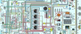
One of the most common domestic problems is the breakdown of any electrical equipment; a wiring diagram will help you understand the devices. The only solution to this problem will be to check the fuses. The topic of today's article is the electrical circuit of the UAZ Bukhanka car on an injector type engine.
So, this article presents answers to some fairly common questions:
- What is the electrical circuit on a UAZ Bukhanka car with an injector engine type?
- How does the electrical circuit of the UAZ car Bukhanka work?
- Where are the fuses located on a UAZ Bukhanka engine type Repair car?
- injector? mounting block.
troubleshooting
Any domestic cars periodically experience problems with the operation of electrical equipment. If you notice that the UAZ wiring is not working properly, you need to diagnose it and check all the elements. If electronic devices malfunction, first of all you need to check whether the fuses in the mounting block have blown. If everything is in order with these elements and the equipment still does not work, for example, if we talk about optics, then it is necessary to check whether working bulbs are used. If the lamps themselves work, then you need to ring the electrical part using a tester (the author of the video about ringing car wiring is Ramil Abdullin).
If the loaf refuses to start, you need to do the following:
- First of all, check the performance of the battery.
- With the battery charged, use a tester to test the circuit from the coil to the generator; often the reason for the inability to start the engine lies in broken wiring. If there are breaks, the thread should be replaced. If oxidation appears on the contacts, they should be cleaned.
- Without a spark, it will be impossible to start the power unit. To diagnose the presence of a spark from the spark plug, remove the high-voltage cable and bring it closer to the body. When you try to start the engine, a spark should jump between the cable and the housing.
- If there is no spark, the problem may lie in the presence of soot and deposits on it. By the way, carbon deposits are often the cause of unstable engine operation and triple formation. To eliminate such a malfunction, it is advisable to clean the spark plugs; detailed instructions for this process are presented here.
basic information
car in UAZ brand fuses Bukhanka is located in a special mounting block, and it, in turn, is located in the air inlet box on the left side of the transport Mounting block. The unit includes all sections of the most important electronic circuits, while supplying them with the necessary fuses and relays. The fuse block of the UAZ car Bukhanka consists of two lines with the fuses and this entire structure is secured with nuts to the vehicle body. If you decide to remove the fuse lines, you will need to disconnect the battery.
The main electronic elements of the circuit include:
- Accumulator battery;
- Electronic fuel pump;
- Fuel Injector Cleaning Filter;
- mixtures;
- Engine control unit;
- Electronic ignition coil;
- Spark plugs;
- Idle sensor Sensor;
- crankshaft stroke;
- Throttle sensor Tachometer;
- air;
- Fan motor cooling the radiator;
- electronic fan motor control relay;
- Indicator that controls engine performance;
- Diagnostic connector.
Wiring diagram Loaf UAZ
In the event of any breakdown of electronic equipment, the current in which the node is responsible for this device will increase, resulting in a short circuit. The wire through which the current passes to the fuse burns out and melts, as a result of which the circuit breaks and the device turns off, but its integrity is maintained. That is, thanks to fuses, the main parts are protected from overheating and a short circuit.
Possible wiring problems
What can lead to wiring problems:
- Broken wires or damaged insulation. In both cases, the only option is to replace the damaged section of the electrical circuit. An open circuit, as well as chafing of cables, can be caused by external factors, for example, if the wiring was laid where there are rubbing mechanisms. Before replacing the cable, it is necessary to eliminate the cause, otherwise the problem will soon occur again. Solving the problem of insulation chafing by wrapping several layers of insulating tape onto the cable is also impractical.
- Short circuit in the system. Such a malfunction can only be determined by diagnosing the electrical circuit using a tester - a multimeter. A short circuit can also be caused by chafing of power cables.
- Voltage surges. Such malfunctions may be caused by the use of too powerful energy consumers. Let's look at the simplest example: you installed a splitter with several sockets. When the voltage consumers are turned on, a higher current charge is supplied to each socket of the cigarette lighter. The cigarette lighter socket is designed for a certain voltage, and if instead of one device two or three devices are powered, then, accordingly, the voltage passing through the socket will be several times higher. This contributes to the appearance of differences in the operation of the electrical system.
- Failure of the safety device. If the fuse blows, it is necessary to replace the failed element. But if burnout occurs too often, then you need to check the socket in which the part is installed. Perhaps the reason lies in voltage surges, so the fuse blows prematurely. The cause of the difference must be eliminated.
- Generator unit malfunction. Problems in its operation can be identified by reduced voltage in the on-board network, as well as dim headlights. Moreover, when the driver presses the gas pedal, the brightness of the optics increases noticeably. This usually indicates a failure of the voltage regulator or worn brushes.
- Oxidation of contacts at the ends of wires. Due to oxidation or damaged contacts, power to electrical equipment is disrupted because charge cannot flow to the device. The problem of contact oxidation may be a consequence of exposure to moisture on the wiring. This problem can be resolved by cleaning the contacts or replacing them. You can use fine-grit sandpaper for cleaning.
Technical characteristics and design features of the ZMZ 409 engine
The ZMZ 409 gasoline engine, equipped with a microprocessor-controlled direct injection system, is based on the cast-iron cylinder block of the ZMZ 406 model unit. The power plant was created specifically to equip UAZ vehicles, as well as Volga (experimental and small-scale versions). It differs from the base engine by an increased piston stroke and modernized pistons, which made it possible to retain the same connecting rods. Depending on the software version, the motors meet Euro 2/3 or 4 requirements. The latest modifications of the motor comply with Euro 5 standards and have modified power and torque curves.
The powertrain serial number, which is the vehicle's VIN number, is located on the left side of the engine block above the front mount mount.
Technical characteristics of the power unit:
- block design - 4-cylinder in-line;
- number of valves per cylinder - 4 (2 for intake, 2 for exhaust);
- cylinder diameter - 95.5 mm;
- piston stroke - 94 mm;
- working volume - 2693 cubic meters. cm;
- compression ratio - 9;
- The order of flashes in the cylinders is 1:3:4:2;
- maximum power (version for UAZ “Bukhanka”) - 112 hp. With. at 4250-4400 rpm;
- torque - no less than 198 N/m at 2500 rpm;
- fuel type - unleaded gasoline with an octane rating of 92 or more;
- direction of rotation of the crankshaft (from the pulley side) is right;
- type of cooling system - liquid, forced type;
- crankcase ventilation system - forced, closed type, operates from a vacuum inside the intake manifold;
- engine weight (with attachments) - 190 kg.
Main features of the engine design:
- the working mirrors of the cylinders are made directly in the material of the cast iron block, without the use of liners;
- main bearing caps are not interchangeable, since the parts are processed together with the block;
- the front cover of the camshaft supports is the same for the intake and exhaust;
- the timing gear bearing caps are machined together with the head, so they cannot be swapped;
- Hydraulic play compensators are installed in the valve drive;
- some engines have intake and exhaust camshafts with identical cam profiles;
- the pistons have recesses on the bottom that prevent contact with the valves in the event of a violation of the valve timing;
- the valves and mounting springs are identical to those used on the engines of the VAZ-2108 car.
To complete the UAZ “Bukhanka” vehicles, several engine modifications were supplied, differing in attachments.