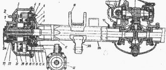
Rear axle of the KamAZ-5511 dump truck, parts, spare parts: (Fig. 8.33) 1 - main gear housing (gearbox); 2, 26 - nuts; 3. 28 — expansion bushings; 4 — crankcase mounting stud; 5 - gasket; 6 - flange; 7 — right axle shaft; 8 — rear axle housing; 9 - plug; 10 — magnetic plug; 11 — left axle shaft; 12 — installation plate; 13 — brake chamber with spring energy accumulator; 14 — caliper with brake mechanism assembly; 15 — hub seal; 16 — oil seal ring; 17, 18 — tapered roller bearings; 19 — bearing fastening nut; 20 — stuffing box; 21 — oil seal housing; 22 — axle shaft gasket; 23 — lock washer; 24 - lock nut; 25 — axle shaft mounting stud; 27 — spring washer; 29 — hub; 30 — wheel nut; 31 — clamp; 32 — spacer ring; 33 — brake drum; 34 — shield; 35 — breather
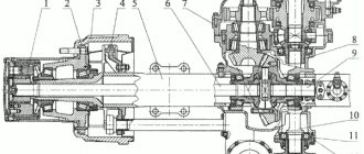
Middle axle assembly KAMAZ, parts, spare parts: (Fig. 8.34) 1 - middle axle housing assembly; 2 — breather assembly; 3 — final drive housing gasket; 4, 8, 14 — studs; 5.16 — spring washers; 6, 17 — nuts; 7.15 — expansion bushings; 9 — axle shaft gasket; 10 — short right axle shaft; 11 - plug; 12 — magnetic plug; 13 — long left axle shaft
After unscrewing the nuts securing the axle shafts, remove the spring washers and expansion bushings. Having screwed two technological bolts M16x1.5-6d-80 into the holes of the axle shafts, remove the axle shafts with gaskets, after which the main gear of the rear or middle axle assembly is removed. The studs are unscrewed from the axle housings, the gaskets are removed, and the magnetic plugs, plugs and breather assemblies are removed. Subsequent work is performed first on one and then on the other side of the bridge in the same sequence for the rear and middle axles. Having unscrewed the lock nut 24 (see Fig. 8.33), remove the lock washer 23, the oil seal housing 21 with the packing 20 and unscrew the nut 19 securing the bearing. Then, using a puller, remove the hub 29 assembled with the brake drum, bearing 18 and the outer ring of the bearing 17. The puller is used to compress the inner ring of the bearing 17 and the oil seal ring 16. Having unscrewed the nuts securing the brake chamber 13, remove the cotter pin, washer, pin connecting the brake chamber rod with an adjusting lever, and a brake chamber. Using a device for removing and installing brake pads, remove the pads 7 (Fig. 8.35) assembled with the linings, the rollers 52 of the pads, the axles of the rollers 55 and the release springs 4. Then remove the pin 8 and the lining 9 of the axles of the pads. Having unscrewed and removed the nuts 28 with spring washers 29, remove the axles 10 of the pads.
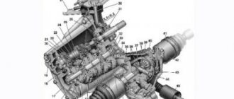
KAMAZ rear wheel brake mechanism, parts, spare parts: (Fig. 8.35) 1 - rear right brake assembly; 2 — rear left brake assembly; 3 — friction lining; 4 - spring; 5 — brake pad; 6, 13, 35 — rivets; 7 — block with linings assembled; 8 - check; 9 — overlay; 10 — block axis; 11, 20 — bolts; 12, 19, 27, 29, 41, 45 — spring washers; 14 - plate; 15 — caliper; 16 — bracket for the pad axles; 17, 47 — plugs; 18 — shield; 21, 53 — cotter pins; 22, 54 — washers; 23 — right adjusting lever assembly; 24 — adjusting washer; 25 — sealing ring; 26, 28, 42 — nuts; 30 — caliper assembly; 31 — expansion fist; 32 — roller; 33 — roller axis; 34 — left brake chamber and expansion cam bracket assembly; 36, 39 — oiler; 37 — worm axis; 38 — right brake chamber and expansion cam bracket assembly; 40 — retaining ball; 43 — bushing; 44 — retainer; 46 — clamp spring; 48 — right lever housing assembly; 49 — lever worm; 50 - worm gear; 51 — housing cover; 52 - finger
Having removed the cotter pin 21, washer 22 and expansion cam 31, remove the right adjusting lever 23. Having unscrewed the bolts securing the brake chamber bracket 38, remove the nuts 42, spring washers 41, bolts and bracket. Then unscrew the bolts securing the caliper 30 to the rear axle housing and remove the caliper assembly. Having unscrewed the bolts 20 with spring washers, disconnect the rear brake flap 18 and the caliper. The specified work is also performed on the other side of the rear or middle axle. The removed parts of the rear and middle axles are washed, blown with compressed air and repaired. If there are breaks or cracks, the parts are rejected. Gears, in addition, are rejected when the working surfaces are chipped or teeth are broken. Damaged threads are restored. The rear and middle axle crankcases (Fig. 8.36) are rejected if there are cracks or breaks on the trunnion 1, broken welds 2, cracks on the flange 3, bent crankcases, if the runout of surfaces B and C relative to surface D over a length of 100 mm exceeds 0.15 mm, as well as when worn; rings for oil seal - up to diameter d1
KAMAZ rear (middle) axle housing, parts, spare parts (Fig. 8.36)
The short and long left axle shafts are rejected if the splines are twisted or crushed, the axle shaft is bent if the radial runout relative to the axis of the centers exceeds 0.15 mm and the flange is bent if its end runout exceeds 0.1 mm, if the flange is worn to a thickness of less than 11.0 mm , in case of scuffing or wear of the conical holes in the flange, if the displacement of the large end of the conical gauge with a large cone diameter of 19.5 mm and an angle of 39 ° relative to the end of the part exceeds 1.0 mm, wear of the neck under the cuffs to a diameter of less than 59.82 mm and splines , if the size measured by rollers with a diameter of 4.4 mm is less than 54.96 mm. The brake drum is rejected if there are scratches, scuffs, ring grooves or wear: working surface - up to a diameter of more than 406.0 mm; landing surface - up to a diameter of more than 275.215 mm; holes for wheel studs - up to a diameter of more than 17.0 mm. Rear wheel hubs are rejected when worn: - surfaces under the wheel rim (installed by inspection); — holes for the outer bearing — up to a diameter of more than 134.988 mm; — holes for the internal bearing — up to a diameter of more than 149.988 mm; — holes for brake drum mounting bolts — up to a diameter of more than 17.0 mm. The brake pad is rejected if the hole for the pad axle is worn to a diameter of more than 28.21 mm and the groove for the pad roller axle is worn to a size of more than 16.18 mm. Bent ribs or rim of the block are eliminated by straightening, broken welded joints are restored. The pad axle is rejected when the support journals under the pad ribs are worn to a diameter of less than 27.58 mm and the journals under the caliper hole are worn to a diameter of less than 21.79 mm. The brake pad roller axis is rejected if there are nicks and wear on the working surface to a diameter of less than 19.4 mm and guides to a flat size of less than 15.82 mm. The pad roller is rejected when the journal is worn to a diameter of less than 39.26 mm and the hole to a diameter of more than 20.3 mm. The adjusting lever assembly (Fig. 8.37) is rejected when the turnkey edges A are worn. If the hole in the bushing is worn to a diameter d > 12.24 mm, the bushing is replaced; if the fit of plug 3 is loosened, the plug is replaced. If the rivet connection between the covers and the body becomes loose, replace the rivets 4. If the gear splines are worn to thickness a
Weight of KamAZ gearboxes 5320 4310 6520 65115 KamAZ diagram
Taking into account the transport container, the weight of the gearbox is:
— on the front axle – 132 kg;
- medium - 186 kg;
— rear – 145 kg.
Choosing a KamAZ gearbox: what you need to know (Diagram of KamAZ gearboxes 5320 4310 6520 65115)
Interwheel locking
The device is mounted on the cross-axle differential. When it is turned on, the torque is divided into equal parts - between the two wheels. When the MBC is turned on, the KamAZ's cross-country ability increases. This is important when driving in difficult road conditions, for example, in icy conditions. The inter-wheel lock must be turned off in time - this will prevent gearbox damage
Center differential (MOD)
The functional purpose of the MOD is to turn on and off the gearbox on the middle axle. It is advisable to do this to reduce fuel consumption when the truck is moving along the highway. If you need to increase the cross-country ability of the vehicle, you should connect the middle axle to the driving process, brought into working condition by means of the MOD.
Thus, the gearboxes on the middle axle are distinguished from the rest by the presence of a center differential - this element has an original, well-recognized shape (pig).
Gearbox flanges
Using flanges, the gearbox is attached to the cardan shaft. Older modifications of the devices are equipped with square flanges, newer models are equipped with round flanges (Euro standard) with spline cutting on the joining plane and axle shaft gears.
Structure and diagram of gearboxes KamAZ 5320 4310 6520 65115
Kamaz gearbox diagram - increasing torque, communicating it in a perpendicular direction. For the gearboxes of the KamAZ rear and middle axles, they are similar, but when assembled they are not interchangeable. The main gear design includes:
cylindrical gear pair (gears with oblique teeth);
bevel gear pair (gears with spiral teeth);
An interwheel differential is also installed in the crankcase on two tapered bearings. It is symmetrical bevel, the same for the rear and middle axle gearboxes. The differential consists of a housing (two cups connected by bolts), a spider with four satellites, support washers, and two semi-axial gears. The cross-axle differential distributes rotation between the wheels. On uneven roads or turns, thanks to this mechanism, the wheels rotate at different speeds. It makes the bridge more efficient and reduces wear on some parts.
The importance of the differential's operation is difficult to overestimate when cornering and when overcoming uneven terrain, but on a slippery road it reduces the vehicle's maneuverability. In such cases, his work is blocked. Activate the lock before crossing a slippery area or road with viscous soil, after a complete stop, with the clutch disengaged. If the cross-axle differential is locked, the vehicle speed should not exceed 10 km per hour, the direction should be straight. Having reached a solid road, it is necessary to disable the locking so as not to damage the main gear.
_______________________________________________________________________________
Rear axle of Kamaz-4308 cars
The rear drive axle of Kamaz-4308 trucks (Fig. 26 and 27) has a final drive with a gear ratio of 4.01. The cross-axle differentials of the Kamaz-4308 rear axle are conical with four satellites located in the wheel hubs, with a cross-axle differential lock, and automatic adjustment levers. The cross-axle differential is controlled pneumatically by a lever (tap) located on the instrument panel. It is possible to install an anti-lock braking system (ABS). Kamaz-4308 drive axles contain main gears fixed in the 9 axle housing using nuts and studs, of which four are equipped with conical expansion bushings 27. The axle housing is equipped with 13 spring supports, 29 wheel hubs connected to 2 brake discs and brake mechanisms 17, which are attached with bolts to the axle housing flange. The transmission of torque from the central main gear to the wheels is carried out using axle shafts 8 and 12 that are completely unloaded from axial load.
Rice. 26. Rear axle KamAZ-4308 1 — sensor bracket; 2 — brake disc; 3 - sensor; 4 - safety valve; 5 — main gear housing; 6 — nut securing the main gear housing; 8 — right axle shaft; 9 — rear axle housing; 11 — magnetic drain plug; 12 — left axle shaft; 13 — spring support; 16 — brake chamber type 20/24; 17 — brake mechanism; 18 — cuff; 19, 20 — tapered roller bearing; 21 — lock washer; 22 — folding washer; 23 — bearing nut; 24 — axle shaft mounting stud; 25 — spring washer; 26 - nut; 27 — expansion bushing for fastening the axle shaft; 28 — axle shaft gasket; 29 — rear wheel hub. The main gear of the rear axle KamAZ-4308 (Fig. 27) is single-stage, consists of a pair of bevel gears with spiral teeth, an inter-axle differential and a rear axle gear housing. The drive bevel gear 2 is mounted on two bevel bearings. Between the inner rings of the bearings there is an adjusting sleeve 23. One of the bearings is located in a cup 6, secured with bolts 58 to the housing 1 of the KamAZ-4308 rear axle gearbox. Between the end surfaces of the gearbox housing and the flange part of the cup, adjusting shims 9 are installed. The cavity of the cup is closed from the outside with a lid into which a double-edged cuff is pressed. A flange for fastening the cardan shaft is installed on the splined end of the drive bevel gear 2. The flange is tightened with a self-locking nut. Adjustment of the engagement in the bevel gear pair of the Kamaz-4308 rear axle gearbox is carried out using adjusting shims 9. The preload of the bevel bearings in the drive and driven gear units is carried out by selecting the linear dimensions of the adjusting bushings 16 and 23, and the bevel differential bearings - by adjusting nuts 24 and 48. Inter-wheel differential rear axle KamAZ-4308 (Fig. 27) - conical, symmetrical, lockable. The locking control is electro-pneumatic, carried out by a tap on the instrument panel. You can only engage the cross-axle differential locking mechanism on a slippery section of the road. Activate when the Kamaz-4308 vehicle is stopped or when driving slowly in a straight line directly in front of a slippery section of the road. The lock should be turned on and off with the clutch pedal depressed.
Rice. 27. Main gearbox of the Kamaz-4308 rear axle 1 — gearbox housing; 2 — drive shaft; 3 — differential assembly; 4 — driven gear; 5, 6 — cup of bearings; 7 - gasket; 8 - flange; 9 — adjusting gaskets; 10 - nut; 11, 20 — differential roller bearings; 12 — conical semi-axial wheel; 13 — satellite; 14 — bearing cup cover; 15 — support washer; 16, 23 — adjusting bushings; 18 - differential cup; 19 — cross; 21 — support washer; 47 - gear bracket; 24, 48 — bearing nuts; 49 — bearing nut stopper; 56 — tapered roller bearing; 58, 59, 61 - bolt. The differential of the rear axle of KamAZ-4308 is mounted on two tapered roller bearings 11 and 20, located in the housing 1 of the gearbox. The differential contains cups 3 and 18, inside of which there are two bevel axle gears 12, which are in mesh with four satellites 13. The satellites 13, with pressed bronze bushings, are installed on the spikes of the cross 19, which is rigidly fixed in the cups 3 and 18 of the differential. Support washers 21 are placed under the ends of the semi-axial gears 12 and satellites 13. The washers are installed with their recesses towards the semi-axial gears, and with their flat surface towards the cups. The cross-axle differential locking mechanism of the rear axle (Fig. 28) is designed to increase the cross-country ability of the KamAZ-4308 vehicle in off-road conditions and improve its traction on slippery roads by distributing torque between the axle shafts of the rear drive axle. The mechanism consists of gear couplings 4, a rod 9 with a fork 2, a membrane pneumatic chamber and a control valve. The cross-axle differential locking mechanism can only be engaged when the vehicle is stopped or moving slowly.
Rice. 28. Locking mechanism for the cross-axle differential of the rear axle KamAZ-4308 1 — rear axle housing; 2 — locking fork; 3 — cover of the locking mechanism housing; 4 — cross-axle differential locking clutch; 5 — locking mechanism housing; 6 — housing gasket; 7 — diaphragm of the locking mechanism; 8 — glass of the locking mechanism; 9 — rod of the locking mechanism; 10 — return spring; 11 — cup cover of the locking mechanism; 12 — pressure spring; 13 - bolt; 15 - low nut; 16 — expanding plug; 18 — adjusting gasket; 19 — sealing gasket; 20 — set screw; 21 — thrust ring; 22, 36 — plug KG 1″; 24 - switch; 44 - magnetic plug. The rear axle housing of KamAZ-4308 is welded from stamped steel beams. Welded to the crankcase beams are a crankcase cover, a flange for attaching the main gear, end flanges for attaching brake calipers, levers for attaching reaction rods and springs. The crankcase journal is welded to the beams using friction welding. The drive axle axle shafts are completely unloaded. Hubs 7 (Fig. 26) of the rear wheels of KamAZ-4308 are mounted on tapered roller bearings 19 and 20 and rest on the axle housing axle. The adjustment of the hub bearings is carried out using an adjusting nut 23, which is locked from turning using a lock washer 21 and a flap washer 22. Brake discs 2 and wheel rims are attached to the wheel hubs 29 with special wheel bolts and nuts. Bearings 19 and 20 of the hub are protected from dirt and dust by two cuffs 18. In the main gear housings of the Kamaz-4308 rear axle gearbox there are filler and drain holes 11 closed with plugs. To equalize the pressure inside the axle crankcase, a safety valve 4 is installed in the upper part of the crankcase. Maintenance of the KamAZ-4308 rear drive axle When maintaining the KamAZ-4308 rear drive axle, the following operations are performed: - check the condition of the wheel hub bearings by heating the hubs; — fasten nuts 6 (Fig. 26) securing the main gear housing to the axle housing; — check and bring the oil level in the drive axle housing to normal. — secure nut 10 (Fig. 27) of the drive axle drive gear shaft flange; — replace the oil in the crankcase of the KamAZ-4308 drive axle; — check the tightness of welded, flanged and threaded connections of the rear axle. Oil leakage is not allowed; — check the operation of the cross-axle differential locking mechanism. When the lock is turned on, the indicator on the instrument panel should light up; — check the condition of the Kamaz-4308 wheel hub bearings (with the hubs removed). There should be no visible holes or cracks on the rollers and bearing races. The rollers must not fall out of the cages; — in addition, in the fall, change the oil in the drive axle housing (after 50 thousand km, but at least once a year). The heating of the hubs is checked by hand. If the hand cannot stand it, heating of the hub is considered unacceptable and it is necessary to adjust and lubricate the hub bearings. To check the KamAZ-4308 rear axle for leaks, it is necessary to supply air through the threaded hole under the axle crankcase safety valve with an excess pressure in the crankcase of 19.6-24.5 kPa (0.20-0.25 kgf/cm2). Oil leakage through the cuffs, joints and welds on the axle housing is unacceptable (slight formation of oil stains on surfaces in the above areas, except for welds, without drop formation is not a rejection sign). To check the oil level, you need to unscrew the inspection hole plug on the rear axle final drive housing. If there is no oil leakage from the control hole, then it is necessary to add oil to its level through the filler hole. To change the oil in the main gear and crankcase of the KamAZ-4308 axle, it is necessary to drain the used oil when it is still warm from heating during operation. Drain the oil through the drain hole by unscrewing the control and filler plugs. The amount of oil to be added is in accordance with the chemical chart. After draining the oil, clean the magnetic drain, control and filler plugs from metal deposits and install them in place. Wash the safety valves of the drive axles with diesel fuel, followed by blowing them with compressed air. The oil level in the Kamaz-4308 rear axle gearbox must reach the lower edge of the inspection hole. Inspection should be carried out after the bridges have been at rest for at least one hour. To change the lubricant in the wheel hubs (with the hub removed), it is necessary to remove the old lubricant, wash the inner cavity of the hub, bearings, nuts and washers with kerosene. Place lubricant between the rollers and bearing cages evenly around the entire circumference and into the cavity of the hub between the bearing races. After replacing the lubricant, adjust the rear wheel hub bearings of KamAZ-4308. To check the fastening of the input flange of the rear axle main gear, place the car on an inspection hole or overpass and place chocks under the wheels. Then turn off the parking brake and set the gear lever to neutral. Use your hands to rock the shaft flange in the longitudinal and transverse directions. If there is a noticeable gap, disconnect the propeller shaft and eliminate the movement of the flange. To do this, it is necessary to disconnect the Kamaz-4308 driveshaft, unscrew the flange mounting nut, remove the flange, cover and reduce the thickness of the adjusting shims 9 (Fig. 27) by no more than 0.1 mm. In this case, gaskets with a thickness of 0.05 mm should remain at the edges of the gasket package. Then secure the cover in the gearbox housing, install the flange and tighten nut 10 to a torque of 588-686 Nm (60-70 kg/cm). To adjust the bearings of the rear wheel hubs of Kamaz-4308, you need to hang the wheels and do the following: - tighten the bearing mounting nut before braking the hub, turning it in both directions so that the bearing rollers take the optimal position; — unscrew the nut approximately 1/6; — bend the projections of the lock washer onto the edge of the nut. Repair of the rear axle of a KamAZ-4308 When repairing, depending on the malfunction, dismantle the drive axle assembly, or only the main gear. Disassemble the KamAZ-4308 rear axle gearbox into the following assembly units, after draining the oil from the rear axle housing into a clean container (for further use): - drive bevel gear; — cross-wheel differential; — driven bevel gear; When disassembling, be sure to check the play in the above assembly units, since the assembly must ensure mandatory preload of the tapered bearings. After complete disassembly, wash and check the gearbox parts. When disassembling the KamAZ-4308 rear axle, it is necessary to check the axial and radial movements in the main drive assembly units, since the assembly must ensure the mandatory preload of the tapered bearings. When inspecting the parts of the KamAZ-4308 rear axle, you should: - check the teeth and the location of the contact patch on the working surfaces of the teeth of the bevel gears; If unacceptable wear or damage (chipping of teeth) is detected, replace with new ones. If the teeth are not properly engaged, find the cause and eliminate it. For spare parts and assembly, the drive and driven spiral bevel gears are supplied as a set, selected for noise and contact patch, so if one of them is damaged, both wheels must be replaced; — check the condition of the surfaces of the crosspiece studs, satellite bushings, the surfaces of the satellite support washers and semi-axial gears, the landing and end surfaces of the semi-axial gears and their installation locations in the differential cups in the cross-axle differential of the Kamaz-4308 bridge. In case of minor damage, you can polish the surfaces with fine-grained sandpaper, and in case of serious damage, replace the parts with new ones. - Inspect all bearings. They must be wear-free, with smooth working surfaces. To disassemble the hub (Fig. 26), it is necessary to unscrew the nuts 26 securing the axle shaft and remove the axle shaft. Unscrew the nut 23 of the bearing and remove the inner race of the bearing 20. Unscrew the fastening bolts and remove the KamAZ-4308 wheel hub assembly with the brake disc. The outer rings of bearings and cuffs should be dismantled if they are replaced. The hub assembly must be done in reverse order. Before assembly, lubricate the seating surfaces on the bridge axle with grease. After installing hub 7, it is necessary to adjust bearings 19 and 20 of the hub. To do this, tighten the nut 23 securing the bearings to approximately 245...294 Nm (25...30 kg/cm) before the hub starts braking, while turning the hub in both directions so that the rollers are correctly installed on the conical surfaces of the rings. Then loosen the nut about 1/6 of a turn. Bend one protrusion of the flange washer onto the edge of the nut. Check hub rotation. The hub should rotate freely by hand, without jamming. To remove the main gear, it is necessary to hang the KamAZ-4308 drive axle, secure it on stands, drain the oil from the axle crankcase, the main gear, unscrew the nuts securing the axle shafts and remove the axle shafts approximately 150 mm on both sides. After unscrewing the bolts securing the main gear to the axle housing, remove it. To disassemble the drive bevel wheel of the main gear of the Kamaz-4308 axle gearbox (Fig. 27), unscrew the nut 10 securing the flange, remove the flange 8. Unscrew the bolts 58 securing the cover of the 6 bearing cup and remove the cover with the gasket. Screwing in the technological bolts M12x1.25x50 (2 pcs.), press out the drive bevel gear assembly from the gearbox housing 1. To disassemble the unit, it is necessary to remove the inner ring of the outer bearing, the adjusting sleeve 23, and then the drive bevel gear with the inner ring of the inner bearing. Press the inner ring of the inner tapered bearing using a puller. To remove, install the edges of the wedges 8 of the puller (Fig. 29) between the inner ring of the bearing and the wheel and, screwing in the screw 6 and the yoke 7, tighten them. Place the grips 1 by the wedges 8 and fix them in this position with screw 3. Pressing the tip 2 against the end of the wheel and screwing the screw 3 into the traverse 4, remove the ring.
Fig.29. Puller for the inner rings of bearings of drive gears and differential cups of the rear axle KamAZ-4308 1 - grip; 2 - tip; 3, 5 and 6 - screws; 4, 7 — traverses; 8 - wedge; 9 - stand. Rice. 30. Removing the inner ring of the Kamaz-4308 differential bearing 1 - grip; 2 - tip; 3 and 5 - screws; 4 - traverse. To disassemble the differential of the KamAZ-4308 rear axle (Fig. 27), you need to unscrew the bolts securing the bearing caps, remove the caps and adjusting threaded nuts 24 and 28. Remove the differential from the main gear. Next, remove the retaining ring and gear clutch of the locking mechanism from the differential cup. If replacement is necessary, press bearings 20 from differential cups 17 and 18. To do this, insert grips 1 (Fig. 30) behind the inner ring of the bearing and secure with screws 3. Resting tip 2 against the end of the differential, screw screw 5 into cross-beam 4 until the inner ring of the bearing is completely removed. After unscrewing the bolts securing the Kamaz-4308 differential cups, separate the cups. Remove the crosspiece 16 with satellites 15 and support washers 17, semi-axial gears 12 with support washers 13. Clean the removed parts and check their technical condition. If there is increased wear or signs of seizure on the surface of the bushings, they should be replaced. Replace cups only as a set (both cups must have the same set number). After replacing the cups, before assembling the differential, you need to press in the inner rings of the bearings 20. When assembling the differential, it is necessary to install the right semi-axial gear with a washer, a cross assembled with bushings, satellites and washers into the right cup of the differential of the Kamaz-4308 drive axle. Insert support washers and left axle wheel into the left cup. Align the differential cups with the factory marks. Tighten both cups with self-locking bolts to a torque of 98-122 Nm (10-12.5 kg/cm). The self-locking bolts for fastening the driven bevel gear must be tightened to a torque of 245-294 Nm (25-30 kg/cm). Install the cross-axle differential into the final drive housing. Tighten the bearing cap bolts to a torque of 100-120 Nm (10-12 kg/cm). When assembling the Kamaz-4308 rear axle gearbox housing, you must remember that the differential bearing caps are not interchangeable, since they are processed together with the crankcase, so each cover must be installed in the place where it was located. Assemble and install the drive bevel wheel assembly unit in the reverse order of its disassembly. After installing the differential in the main gear housing, it is necessary to adjust the engagement of the driven and driving gears according to the lateral clearance, which should be 0.25 - 0.40 mm and the contact patch. The lateral clearance and contact patch in engagement can be determined by simultaneously adjusting the location of the drive bevel wheel assembly 7 and the differential. Adjusting the main gear of the KamAZ-4308 axle gearbox (Fig. 27) includes adjusting the preload of the differential bearings and bearings of the drive bevel gear, as well as adjusting the side clearance and contact patch of the bevel pair. To ensure preload in the tapered bearings of the drive bevel wheel assembly in the presence of axial movement, it is necessary: - reduce the height of the adjusting sleeve 23 by grinding or replacing bushings from spare parts by the amount of axial movement plus 0.04-0.06 mm; — tighten the nut 10 securing the flange 8 to a torque of 588-686 Nm (60-70 kg/cm); — check the rotation force of the 5 bearing cup, which should be equal to 10-24 N (1.00-2.50 kgf). The turning force must be measured with continuous rotation of the glass in one direction after at least five full revolutions. In this case, the bearings must be lubricated, and the bearing cup cover must be moved so that the cuff does not provide resistance to the rotation of the gears. After installing the differential drive bevel gear into the Kamaz-4308 gearbox housing, it is necessary to adjust the side clearance, which should be in the range of 0.25-0.40 mm, and the contact patch of the bevel pair using nuts 24 and 48. To adjust the bearings of the Kamaz-4308 differential, it is necessary to tighten the adjusting nuts 24 and 48 evenly on both sides until the distance between the bearing caps increases by 0.1-0.2 mm. Having adjusted the bearings, you need to finally tighten the bearing cap bolts with a torque of 380-460 Nm (38-46 kg/cm) and lock them with lock washers. Assemble the main drive of the bridge. Ensure the tightness of all flange and threaded connections that have access to oil cavities with sealant. Replacing the rear axle of KamAZ-4308 To remove the rear axle of KamAZ-4308, you need to unscrew the plugs from the drain holes of the rear axle housing and wheel drives. Drain the oil. After draining, clean and screw in the plugs. Brake the vehicle using the parking brake system and lift the rear end by the frame. Remove the wheels by unscrewing the wheel nuts. Disconnect the compressed air supply air hoses from the brake chambers and the cross-axle differential lock drive chambers. Disconnect the electrical wires from the lock control sensors. Unscrew the bolts securing the flange of the Kamaz-4308 propeller shaft. Remove the bolts and move the driveshaft to the side. Unscrew the nut securing the horizontal link bracket of the brake force regulator and move it to the side. Place a lift under the rear bogie with the drive axle and hang it up slightly. Disconnect the upper reaction rod from the axle housing. To do this, you need to unscrew the bracket nuts and remove the spring washers. Pull the reaction rod up. Disconnect the lower reaction rods of the KamAZ-4308 rear suspension. To do this, you need to unscrew the nuts, spring washers and bolts of the left lower reaction rod. Take her aside. Repeat the same for the right lower reaction rod. Raise the rear of the car. Roll out the lift with the drive axle from under the Kamaz-4308 vehicle, place a stand under the frame and lower the vehicle onto it. To install the drive axle, you must install it on a lift. Raise the car and place it on a stand. Roll the drive axle on a lift under the suspension. Raise the axle with a lift and connect the suspension elements to the axle housing. The tightening torque of the bolts and nuts securing the upper and lower reaction rods should be 435.1-490.5 Nm (44-50 kg/cm). Next, lower the lift rod and move it to the side. Attach the brake force regulator rod to the KamAZ-4308 drive axle and secure it. Tighten the nut. Connect the propeller shaft to the drive axle flange, insert the bolts into the holes, put spring washers on them and tighten the nuts. Connect compressed air supply pneumatic hoses to the brake chambers and the interwheel differential lock drive chambers. Connect the electrical wires to the locking control sensors. Install the wheels on the hub, screw on the nuts and tighten them in a diagonal sequence with a torque of 540-670 Nm (54-67 kg/cm). Check the stroke of the rear axle brake chambers and, if necessary, adjust the brake mechanisms. Unscrew the filler plugs in the main gear and in the wheel drives of the rear axle. Fill with oil to the level of the inspection hole. Screw in and tighten the filler plugs. Check the operation of the drive axle with a run. Overheating of wheel hub bearings and final drive bearings is not allowed.
_______________________________________________________________________________
_______________________________________________________________________________
_______________________________________________________________________________
- Clutch KamAZ-5320 and its components
- Repair of PGU and Kamaz clutch master cylinder
- Gearbox gearbox KamAZ 141
- Gearbox gearbox KamAZ ZF 16
- Gearbox 152 Kamaz with divider
- Gearbox gearbox 154 Kamaz
- Gearbox Kamaz-4308
- Clutch of a Kamaz-4308 car
- Clutch and gearbox KamAZ-65115
- Disassembly and assembly of Kamaz-4310, 55111, 43118 gearboxes
_______________________________________________________________________________
- Cylinder block, head and valves Kamaz-740
- Fuel system of Kamaz-740 diesel engine
- Adjustments and repairs of fuel injection pump Kamaz-740
- Drive axles of the Kamaz-4310 vehicle
- Repair of Kamaz drive axle gearbox
- Rear axle KamAZ-4308
- Axles and suspensions of Kamaz-65115 dump trucks
- Installation of Kamaz cardan shafts and axles
- Repair of Kamaz vehicle transfer case
- Kamaz power steering - adjustments and repairs
- Repair of Kamaz steering gear parts
- Steering parts Kamaz-4308
- Parts of the brake system Kamaz-4308
- Brake system and brake drive Kamaz
- Repair of brake valves and Kamaz compressor
- Suspension Kamaz-4310, 55111, 43118 and their parts
- Frame and suspension of the Kamaz-4308 car
- Cabin details and platform KamAZ-65115
- Cabin components Kamaz-4308
- Platform mechanism of Kamaz vehicles
- Klintsy KS 65719-5K truck crane based on KamAZ-6522 chassis
- Truck crane KC-35719-7-02 based on Kamaz-43118 chassis
- Truck crane Galichanin KC-55713-1K based on KamAZ-65115 6x4
- Ivanovets KS-45717K-1/1R truck crane based on KamAZ-65115 chassis
- Ivanovets KS-3577-3/4 truck crane on KamAZ-43253 4x2 chassis
Kamaz gearbox diagram
Main characteristics of KamAZ gearboxes
The mechanism is assessed according to the following indicators:
gear ratio of the unit;
angular speed of shaft rotation;
The gear ratio of the Kamaz gearbox scheme is the ratio of the number of teeth of the driven wheel to a similar parameter of the drive wheel. For KamAZ vehicles, mechanisms are produced with gear ratios of 4.98, 5.11, 5.43, 5.55, 5.94, 6.33, 6.88, 7.22. The higher the gear ratio, the more difficult road conditions the car can overcome and withstand the greater load. For trucks without trailers, gearboxes with gear ratios of 6.53, 5.94 and 5.43 are recommended, for road trains - 7.22, 6.53 and 5.94. Depending on the terrain: for plains - 5.94, on rough terrain - 6.53, mountainous - 7.22.
The most common malfunctions of KamAZ gearboxes, their elimination
KamAZ gearboxes contain reliable mechanisms. With regular maintenance and compliance with the manufacturer's operating recommendations, it will serve without fail for decades. The most common:
An excessive increase in the temperature of parts can be caused by incorrect tooth settings, lack or excess of oil in the crankcase, or excessive bearing tension.
Noisy operation increases due to loose or worn bearings and an incorrectly adjusted clutch.
Oil leakage is possible due to wear of the cuffs and contamination of the breather.
Adjustment of the KamAZ 65115 rear axle gearbox diagram
When adjusting the reduction gear of KamAZ axles, the following parameters are adjusted:
contact patch of gears;
lateral clearance in the mesh of the wheels of a gear pair;
tension of tapered roller bearing rings;
When installing a differential, it is important that the ring gears of the drive and driven wheels are positioned symmetrically.
Purchase of KamAZ gearboxes and spare parts for them
When operating and maintaining the KamAZ 65115 rear axle gearbox, the manufacturer’s recommendations should be followed. In our trading company you will find all the spare parts necessary for the maintenance and repair of gearboxes. Parts and components are guaranteed. Buying a KamAZ gearbox in our store means ensuring uninterrupted operation of the vehicle for a long time.
We offer customers original spare parts and components, affordable prices, high-quality service: convenient ordering, fast shipping.
Call to get a free consultation or buy a KamAZ gearbox and spare parts for it.
The KamAZ gearbox is one of the main elements of the transmission. It is necessary to transmit torque from the crankshaft to the chassis. The unit is subject to enormous loads, since it is it that drives the truck’s axles. It rotates constantly, so the main importance in its design is given to bearings and gears, which are constantly subject to friction. In order for all parts to function correctly, lubricant must be added to the crankcase in a timely manner.
Today there are more than 140 types and models of gearboxes for all types of bridges. All of them are assembled on the same crankcase, with the only exception being the front gearbox for all-wheel drive trucks with a 6x6 wheel arrangement.
In addition to the peculiarities of installation on bridges, gearboxes are disconnected from each other by the size of the gear ratio. It determines the running characteristics of KamAZ, and depends on the number of teeth of the spur gears.
The gearboxes of all axles on a truck must have the same gear ratio - installing gearboxes with different gear ratios will inevitably lead to breakdown. Trucks that primarily operate at low speeds are equipped with a lower gear ratio. But for vehicles that must develop high, stable speeds (tractors, flatbed highway trucks) - gearboxes with a high gear ratio.
The KamAZ 5320 4310 6520 65115 gearbox circuit fails very often. Despite this, timely maintenance of the unit will help to avoid troubles. From the experience of car owners, the gearbox is mainly susceptible to the following malfunctions:
— overheating of the main gear;
Malfunctions that occur on KamAZ vehicles are caused by a variety of factors, not least of which is the wear of the working surfaces of the elements. The gearbox, like any other truck unit, is no exception - among the main reasons for its breakdowns are low-quality or unsuitable oil, bearing wear, leakage of the gearbox housing, and incorrect bearing tension.
The following signs may indicate that the gearbox needs repair:
- noise or metallic grinding noise in the rear of the truck that occurs when the vehicle is moving or braking. If we are talking specifically about gearbox failure, extraneous noise appears at a speed of 20 km/h and disappears when accelerating to 80 km/h;
— noise appears if you turn the car into neutral at a speed of 80 km/h and turn off the ignition.
It is best to carry out gearbox repairs in a specialized service center, which guarantees both the quality of spare parts and a high level of repair work.
Gearbox repair consists of the following steps:
— draining the oil and dismantling the drive axle;
— analysis of the drive axle into its main components;
— replacement of worn parts with similar new ones, assembly and adjustment of the bridge;
— testing the assembled bridge - for absence of rattle, maximum heating (75 C);
— installation of the finished assembled bridge at its original location.
Gearbox for KamAZ 4310 family equipment.
main gear
- this is a transmission element, consists of a crankcase, a drive shaft with a bevel gear, an intermediate shaft with a driven bevel and a driven cylindrical gear, a driven cylindrical gear. The gearbox converts torque from the gearbox and transmits it to the drive axle. The traction and speed characteristics of the KamAZ-4310 vehicle, as well as fuel consumption, depend on the design of the main gear (gearbox) and the number of teeth.
Main gear and differential of the rear axle of the KamAZ-4310 vehicle:
1 - crankcase; 2 — driven bevel gear; 3 — driving cylindrical gear; 4, 6, 10, 18, 20 — tapered roller bearings; 5 — cup of bearings; 7, 19 - adjusting washer; 8, 17 — shims; 9 — adjusting nut; 11 — differential cup; 12 — cross; 13 — semi-axial gear; 14 — driven cylindrical gear; 15 - roller bearing; 16 — gasket; 21 — driving bevel gear; 22 - drive shaft; 23 — bearing cover; 24 - stopper.
Main gear of the KamAZ-4310 family
The gearbox is mechanical, two-stage (with two pairs of gears - a bevel pair with spiral teeth and a cylindrical pair with oblique teeth). Gear ratio 7.22.
Filling tanks: front axle - 5.3 l, intermediate and rear axles - 7 l. The oil used is TSp-15k (up to -30°C), TSp-Yu (up to -45°C), TM5-12RK (below -45°C). Substitute for TDP-15V (up to -25°C).
Principle of operation
While the vehicle is moving, torque from the engine is transmitted to the gearbox, and then, through the gearbox/final drive and differential, to the vehicle's drive shafts.
The main characteristic of the gearbox is the gear ratio, which shows the ratio of the number of teeth of the driven gear associated with the wheels to the drive gear associated with the secondary shaft of the gearbox. - A larger gear ratio allows the car to accelerate faster (increasing torque), but the maximum speed value decreases. - A smaller gear ratio increases the maximum speed, but the car will accelerate more slowly. The gear ratio is selected taking into account the characteristics of the engine, gearbox, and wheel size.
Final drive device
A classic gear reducer with a single pair of gears consists of two gears: The smaller drive gear is connected to the output shaft of the gearbox. The driven gear is larger than the drive gear and is connected to the differential, i.e. with car wheels.
Gearboxes with a double pair of gears have two pairs of gears; they can be double central (in drive axles) or double spaced (in the hub of drive wheels), which are usually used for trucks with a high gear ratio.
Types of gear connection
- Cylindrical.
Used on front-wheel drive vehicles in which the engine and gearbox are transversely located. Gears with chevron and oblique teeth. - Conical.
Used on rear-wheel drive cars and trucks, including KamAZ-4310. A serious disadvantage of bevel gears is their large weight and size characteristics, difficulty in processing, and noise during operation. - Hypoid.
It features low load on the teeth and reduced noise levels. In this case, due to the displacement in the meshing of the gears, sliding friction increases and efficiency decreases, but it is possible to lower the driveshaft as low as possible. - Worm.
Rarely used in the design of automobile transmissions due to the complexity of manufacturing and high cost.
Spare parts for KAMAZ-4310 KamAZ-5490 gearbox ZF gearbox Transfer cases Gearboxes
Buy spare parts from us:
| We complete applications of any complexity, competitive prices, and a system of volume discounts. |
| We provide a clear guarantee of the quality of spare parts from manufacturers |
| Prompt delivery throughout Russia |
| Call or write to [email protected] Information will be required: car model, year of manufacture, unit model, Euro class. |
Gearbox diagram KamAZ 5320 4310 6520 65115
Gearbox diagram KamAZ 5320 4310 6520 65115 is a mechanism designed to transmit the rotation of the crankshaft to the wheels. It causes the truck axles to rotate and experiences enormous loads.
The unit consists of a main gear and a differential. They are placed in a crankcase, which is mounted on special flanges in the central part of the bridge. The normal functioning of the unit and the interaction of parts is ensured by lubrication. The crankcase is filled with oil through the filler hole, and its level is monitored through the control hole in the crankcase cover. Grooves on the inner surface of the crankcase and channels in its walls serve to supply oil to the bearings.
Middle gearbox malfunctions: signs and causes
The main symptom of gearbox failure is the appearance of extraneous noise when the truck moves at low speed (about 20-25 km/h). This symptom can also be observed when driving at a speed of about 80 km/h in neutral gear.
The following malfunctions are most typical for middle axle gearboxes:
- the main gear overheats due to excess/lack of oil, improper adjustment of teeth and bearings;
- the bearings have succumbed to natural wear and therefore need to be replaced;
- Oil leakage occurs due to wear on the cuffs or contamination of the breather.
Malfunctions of the KamAZ gearbox are, as a rule, a consequence of overloads or operation of equipment in difficult climatic conditions. In some cases, the middle axle gearbox can be repaired. However, if the housing is severely damaged, it is safer and more cost effective to replace the unit.
KamAZ drive axles
The KAMAZ family of vehicles uses many different drive axles, which have both significant and non-significant design differences. All KAMAZ drive axles can be converted into five types shown in the figure.
The drive axles of all-wheel drive and non-all-wheel drive vehicles differ in the design of the crankcases and final drives. The designs of various models of drive axles of all-wheel drive vehicles are largely identical and differ in the presence of a cross-axle differential locking mechanism (IDL), main gears, hubs and brake elements. The front drive axles of all-wheel drive vehicles differ from the intermediate and rear axles in the design of the housings, main gears, and the presence of rotating mechanism elements. The design of various modifications of the front drive axles of all-wheel drive vehicles is largely identical and differs in the main gears and elements of the braking mechanism.
The main differences between different models of non-all-wheel drive axles: disc or hub wheel mounting; reinforced crankcase beam (sheet 14 mm); presence or absence of ICD, reinforced axle shafts; various elements of brake mechanisms for different brake chambers; various main gears with different gear ratios (7.22; 6.53; 5.94; 5.43); and other minor design differences.
Some of the most commonly used drive axles and their main design differences are presented in Table 31.
- Repair of KamAZ drive axles
- Replacement of KamAZ axles
Rice. 180. Axles of the KAMAZ family of vehicles
Table 31.
| Bridge | Carter | main gear | Hub | Brake mechanism | Brake chambers | Fist |
| Axles of all-wheel drive vehicles xxx-23xxxxxxxxx front | ||||||
| 4310-2300010 | 4310-2301010 | 4310-2302010 | 4310-3103011 | As part of bridges | 100-3519210 | 4310-23004062 4310-23004064 4310-23004065 |
| 43114-2300012 | 43114-2302010 | 4310-3103009 | ||||
| 4326-2300010 | 4326-2302010 | 4310-3103011 | 100-3519210 | |||
| Axles of all-wheel drive vehicles ххх-25ххххххх middle and ххх-24ххххххх rear | ||||||
| 4310-2400010 | 4310-2501010 | 4310-2402010 | 4310-3103011 | 4310-3502010 | 100-3519210 | 4310-2403070 4310-2403071 |
| 4310-2500010 | 4310-2502010 | |||||
| 43114-2500010 | 43114-2501007 with ICD | 55112-2502011 | 4310-3103009 | |||
| 43114-2400012 | 43114-2402011 | |||||
| Axles of four-wheel drive vehicles xxx-25ххххххх middle and ххх-24ххххххх rear | ||||||
| 53229-2500021 | 53229-2501007 with ICD | 53229-2502011 | 65115-3104010 | 53229-3502010 | 100-3519100 | 53229-2403070 53229-2403069 |
| 53229-2400021 | 53229-2401007 with ICD | 53229-2502011 | ||||
| 53215-2400010 | 5320-2401010 | 53215-2402011 various gear options | 53205-3104010 | 5511-3502010 | 53205-2403070 53205-2403069 | |
| 53215-2500010 | 5320-2501010 | 53215-2502011 various gear options | ||||
On KamAZ vehicles with a 6x4 wheel arrangement, two drive axles are installed - intermediate and rear. The design of the bridges is similar. The difference lies in the installation of a locked center differential and individual original parts mating with it in the main gear of the intermediate axle.
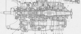
In Fig. 181 shows a cross section of the rear and intermediate drive axles. Each KamAZ drive axle consists of an axle housing, main gear, differential and axle shafts.
Rice. 181. Rear axle: 1 — spacer ring; 2 — brake drum; 3 — shield; 4 — safety valve; 5 — main gear housing; 6 — hairpin; 7 — crankcase gasket; 8 — right axle shaft; 9 — rear axle housing; 10 — control plug; 11 — magnetic drain plug; 12 — left axle shaft; 13 — spring support; 14 — rocket rod bracket; 15 - bolt; 16 — brake chamber with spring energy accumulator; 17 — brake mechanism; 18 — cuff; 19, 20 — tapered roller bearings; 21 — bearing fastening nut; 22 — axle shaft gasket; 23 — lock washer of the lock nut; 24 - lock nut; 25 — axle shaft mounting stud; 26 - nut; 27 — spring washer; 28 — expansion sleeve; 29 — hub; 30 - wheel clamping The bridge consists of an axle housing, main gear, differential and axle shafts.
The intermediate and rear axle housings are welded, made of stamped steel beams, to which are welded flanges for attaching the main gear housings and brake calipers, wheel hub axles, reaction rod mounting brackets and spring supports. On the axle housings of dump trucks, mounting plates are welded for fastening the spring supports.
On KamAZ-53229 and KamAZ-65115 vehicles, the installation of drive axles (Fig. 182) with a cross-axle differential locking mechanism is provided, while the main gear differs in that the left cup of the cross-axle differential is made with splines for installing its locking clutch (see Fig. 183 ).
Rice. 182. Drive axle : 1 - brake chamber with spring energy accumulator; 2 — brake drum; 3 - hub; 4 — bearing nut; 5 — rear brake; 6 — left axle shaft; 7 — axle housing; 8 - safety valve; 9 — transmission of the main bridge; 10 — axle shaft right
Rice. 183. Main gear of the drive axle (fragment)
The bridge beams are strengthened by increasing the thickness of the walls.
The axle shafts have been strengthened due to a change in steel grade and an increase in the number of splines from 16 to 20.
The cross-axle differential locking mechanism is installed in the housing of the rear and middle axles. To ensure remote activation of the locking mechanism in the cockpit, there is a button with the corresponding symbol on the instrument panel. When the key is pressed, the electric pneumatic valve circuit is closed and air enters the diaphragm chamber. The piston, moving the locking fork, connects the axle shaft coupling with the differential cup coupling. When the lock is activated in the cockpit, the warning lights on the instrument panel light up.
When carrying out maintenance (service C), to check the operation of the inter-axle differential locking mechanism, first turn on the inter-axle lock, and then press the inter-axle lock enable button, and the two indicator lamps for turning on the inter-axle locking of the drive axles should light up.
Engaging the lock is only permitted in slippery, muddy road conditions.
The lock should be engaged immediately before a slippery section of the road. When one of the wheels slips, the lock cannot be engaged. In this case, it is necessary to disengage the clutch and engage the lock after stopping the car. Switching the lock on and off should be done with the clutch pedal depressed.
When driving onto a hard, dry road, the lock must be turned off. Driving with the lock engaged will cause parts to break.
The main transmission of the bridges is two-stage. The first stage consists of a pair of bevel gears with spiral teeth, the second stage - of a pair of cylindrical helical gears.
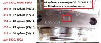
For flat operating conditions of road trains, the recommended gear ratio is 5.94; for mountain conditions - 7.22; for rough terrain - 6.53. Changing the gear ratio of the main gear is achieved by installing gears with different combinations of teeth in a cylindrical pair (see Table 32).
Table 32. Main gear ratio depending on the number of gear teeth in a cylindrical pair
The main gear of the driving front axle (Fig. 184), unlike the main gears of the intermediate and rear axles, is attached to the axle housing with flanges located in a vertical plane. Original parts of the main drive (Fig. 185) of the front axle: cup 3 of the wheel differential, housing 31 of the main gear, input shaft 11, cover 17, bearing 8. The remaining parts and assembly units are unified with the parts and assembly units of the main drive of the rear axle.
Rice. 184. Front drive axle : I — front brake block; 2 — pad roller; 3 — expanding left fist; 4 - screw-in fitting; 5 — adapter fitting; 6 — air supply head; 7 — left steering knuckle housing; 8—oiler; 9—steering knuckle lever; 10—main gear of the front axle; 11 — adjustment lever; 12— ball joint of the steering knuckle; 13 — inner left fist of the hinge; 14 - plug; 15 — joint knuckle liner; 16 — hinge disk; 17 - cuff; 18 — lower lining of the fist; 19, 24, 34 — bearings; 20 — cuff padding; 21 — brake flap; 22 — front brake caliper; 23 — brake pad axis; 25 — left steering knuckle axle; 26 — hub with brake drum; 27, 32—lock washers; 28—drive flange; 29 — air shut-off valve; 30 — outer joint knuckle; 31 — bearing lock nut; 33 - bearing nut
The front axle housing is cast as one piece with the left short axle housing. The right casing is pressed into the axle housing. Ball joints with welded pins are attached to the flanges of the axle housings on studs. Bronze bushings are pressed into the ball joints, in which the internal cams of the constant velocity joints are installed.
The steering knuckle housings are located on the kingpins, which rotate on tapered roller bearings. Trunnions and brake calipers are attached to the steering knuckle housings with studs. Bronze bushings are pressed into the trunnions, in which the outer knuckles of the hinges rotate.
Torque from the inner knuckle to the outer knuckle is transmitted through a constant velocity joint. At the splined end of the outer knuckle there is a drive flange, which is attached to the hub with studs.
Rice. 185. Main gear of the front axle: 1 — bearing cover; 2 — driven cylindrical gear; 3 — differential cup; 4 — support washer of the semi-axial gear; 5, 13, 14, 24, 25 — tapered roller bearings; 6 — semi-axial gear; 7 — satellite support washer; 8, 22 — cylindrical roller bearings; 9 - key; 10 - plug; 11 - input shaft; 12 — driving bevel gear; 15 — cuff; 16 - flange; 17′, 27 — covers; 18, 26 — bearing cups; 19, 30 — adjusting washers; 20 — spacer sleeve; 21 — driven bevel gear; 23 — driving cylindrical gear; 28 — support washer; 29 - nut; 31 — main gear housing; 32 — differential crosspiece; 33 — satellite; 34 — adjusting nut; 35 — nut stopper; E - adjustable size