Assembling a homemade cultivator
- drill with a powerful gearbox;
- gearbox from a grinder;
- gears;
- rear and front sprocket from the Karpaty motorcycle;
- chain from the Karpaty motorcycle;
- bolts and nuts of different diameters;
- metal profiles for welding the body and chain guides;
- pin and bearings with a diameter of 16 mm.
Tools used during assembly:
- Bulgarian;
- metal file;
- welding machine.
When assembling the body, it is necessary to select the dimensions of the metal profiles to match the dimensions of the working body of the cultivator. They depend on the size of the drill and the external gearbox, so there are no clear instructions for cutting metal profiles, only approximate dimensions are indicated.
Cultivator instead of a shovel
Hectares of dug up and loosened soil will not add either strength or health. Especially if the tedious procedure must be carried out every spring and autumn. And digging up 6 acres by hand is a labor-intensive task.
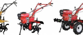
An electric cultivator can help the summer resident, facilitate and speed up the process. Garden tools cultivate and loosen the soil, revealing its layers, and break up the earthen lump, saturating it with oxygen. With the help of an electric assistant, you can remove weeds and hill up plants.
Electric cultivator
Attention! The choice of the tool you need depends on the type of beds and the set of crops grown. If this is a greenhouse or a zoned area with a flower bed, vegetable garden and garden, then light manual options are suitable. To handle large areas, higher-end power tools are required.
The approximate cost of a cultivator created in industrial conditions varies from 5 to 30 thousand rubles. depending on the type. And if you also need a lawn mower, a lighting system for seedlings, drip irrigation in a greenhouse, and much more that you want to mechanize and improve, then this amount can be saved.
Hand cultivator
To help the farmer - 5 cultivator options, collected and tested by Russian summer residents. To create inventions, you can use ordinary tools and spare parts that you have on hand.
DIY walk-behind tractor frame
All parts of a homemade walk-behind tractor are located on one frame. That is why special attention should be paid to the manufacture of this part of the equipment. The steering wheel with control levers can be removed, for example, from the Izh motorcycle. All that remains is to weld it to the rear ends of the side members, which, by the way, are best made from a steel water pipe. An inch and a quarter diameter will be sufficient. By the way, the ends of the side members should be bent upward, and in the rear part they should also be counter-connected by welding.
Weld the cross member along the side members. It will become a stop for the chain tensioner of the first stage of the transmission. You also need to provide:
platform and bracket on which the battery is mounted;
second stage chain drive housing;
bracket for attaching a cultivator subframe (or a biaxial trolley).
A milled channel No. 8 can serve as a bracket for attaching the cultivator subframe, and an M10 bolt can serve as a tensioner for the first stage power transmission chain.
DIY walk-behind tractor engine
It’s worth mentioning right away that the operating principle of a scooter/motorcycle engine, from which the motor is usually removed, is slightly different from the operating principle of a walk-behind tractor. That is why it will have to be optimized a little. First of all, it is worth determining the engine cooling system. If it is passive air, you need to convert it to active. To save fuel, increase traction and make starting easier, it is worth replacing the valve with a reed valve.
The best engine option for a homemade walk-behind tractor will be a two-stroke gasoline 13-horsepower engine. It can be removed from the Ant scooter. The choice fell on this model, because it already has forced air cooling of the engine. In this case, your walk-behind tractor will avoid overheating at low speeds, which means it will serve for a long time without breakdowns. Experts also recommend considering the option of installing the engine from the IZH-Planet-3 motorcycle. It has 18 horsepower, which will increase the productivity of equipment.
DIY electric cultivator from a drill
Digging up gardens every year is unlikely to be a pleasure for anyone, so many DIYers come to the decision to develop semi-automatic devices that can save effort and time, which is uselessly and painfully spent on routine digging of soil.
Watch the first part of the video about how this design of an electric cultivator based on a drill was made, and the final part is devoted to testing the actual operation of the manufactured cultivator in the field.
Products for inventors Link to the store.
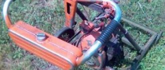
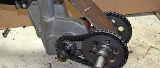
The author of this interesting model, created with his own hands, used a heavy and quite powerful drill as a propulsion device. A cultivator was created on its basis. Since the budget was limited, we had to implement several non-standard moves. Of course, after the drill, which has its own editor, we still needed an additional gearbox, which would allow us to get more power at lower speeds. A gearbox from a faulty angle grinder with a power of 1.5 kilowatts was used as an intermediate one. Since the power plant should be located at the bottom, it was decided to turn the drill with the handle up. The cartridge clamps the remainder of the shaft of the cut off engine.
DIY electronics in a Chinese store.
Next, we used a piece of strip purchased at a hardware store. Strip width 40 millimeters, thickness 4 millimeters. The length of the strip from the edge of the drill gearbox to the edge of the grinder gearbox. All sizes depend on the devices used as the basis.
A square profiled pipe 25 by 25 of the same length is installed and welded on top of the strip. The wall thickness is 2 millimeters. Next, a bracket is made from the same strip. Its radius is equal to the radius of the drill gearbox. After this, the bracket is welded to the strip, and two 8-point bolts are welded on the sides of the free part.
Next, a clamping device is made. The edges are bent in the opposite direction from the applied force so that the washers do not slide off the bracket while tightening the nuts, and the slots for the bolts were made with a grinding wheel installed in another grinder. The washers and nuts are tightened.
A strip is welded, the length of which is equal to the width of the gearbox. Next comes a strip molded to the shape of the upper part of the gearbox. In the middle, opposite the mounting hole, holes are drilled to attach the gearbox to this entire structure. Two strips with cuts for bolts, so as not to bend the strips, are attracted to the gearbox with bolts.
Next, two strips cut at 45 degrees fasten the side strips to the main supporting structure.
The sprocket from the Karpaty moped is used here. The internal slots had to be ground down a little, the skirt from the sprocket had to be cut off, and only in this case did it fit very tightly into the mounting position for the grinder discs. Accordingly, everything was tightened with a nut. There were fears that the sprocket would slip, but the direction of rotation of the shaft coincided with the direction of the thread. Accordingly, the more force developed on the shaft, the stronger the sprocket was attracted to the bottom nut.
In principle, the energy unit of a homemade cultivator based on a drill is almost ready. It can be put aside.
Now we need a bearing cage. You can order them from a turner, but due to the lack of material, a compromise was found.
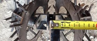
A pin with a diameter of 16 millimeters was used as a power shaft for the cultivator and, accordingly, bearings with an internal diameter of 16 millimeters were chosen for it. The outer diameter of the bearings was 35 millimeters. Since the outer diameter of the bearing was 35 millimeters, an ordinary steel water pipe with an inner diameter of 35 millimeters was used as a race. The 180902 bearing fits in there more or less freely. Used on domestic generators. It was not difficult to make a clip from a pipe.
Pipe with an internal diameter of 35 millimeters. A ring approximately 30-35 millimeters wide is cut. Next, a slot is made in the pipe with a grinding wheel and pieces of 40×25 strip are welded along its edges. A hole with a diameter of 6.2 millimeters was drilled in the middle of these segments. A 6 mm bolt is inserted from below, a washer and nut are inserted from above, and the bolt is scalded from below. You will need four of these clips.
Next, two pieces of 25x25 square profile are used as a supporting chassis for the entire structure. In order to avoid difficulties in rotating the shaft, we use a technological trick. We insert the shaft into the bearings and secure it with nuts. Now we attach the clips to the profile. A piece of strip 40 by 4 mm, approximately 160 mm long, secures the prepared clips into one piece. The weld is only tacked.
Next, by slightly loosening the bearing nuts holding the cage, the shaft moves to the side and the whole thing is boiled. This is necessary in order not to overheat the bearings, since the steel in them is hardened and rapid heating and gradual cooling will soften the bearing material. In addition, the lubricant may burn out. Therefore, it is better not to overheat the bearings, and when carrying out welding work on the races, it is better to pull them out.
Next, the nut is unscrewed on one side, the bearing is removed and the gear is installed. The inner diameter of the large gear in this case was slightly smaller than the size of the nut by 16, so the nut had to be sharpened a little and then the nut was pressed inside the gear on huge disks. The gear is screwed onto the shaft and the bearings are reassembled, the gears are unscrewed and assembly begins.
In the upper part of the power plant there are two sections of profile pipe 25 by 25, length approximately 320-340 millimeters. The profile is folded in half, because here the rotational force will be transmitted from the top. In order to prevent this square profile from being twisted by the propeller, it was decided to bring its shape to a rectangle.
The second half-meter section of the stud with a diameter of 16 millimeters is equipped with a second pair of races with bearings, and the second gear caused problems. Its internal diameter turned out to be slightly larger than 16 millimeters, so the nut was screwed onto the hairpin, then paper was wound around the hairpin and this gear was put on it. Only after this the gear was welded around the perimeter of the nut. Welding was carried out in an unusual way. The gear was recessed to half its height in water, therefore, welding work in the gear did not overheat.
Next, the gear moves down until the teeth mesh tightly. The lower race lowers until it rests against the nut holding the gear. The upper frame is aligned with the height of the vertical profile. There is a small gap here. We insert strip pieces there and secure them by welding. Then we remove the bearings to the welding zones and properly scald the cage.
A section of strip 4 by 40 and 75-80 millimeters long is welded flush in height with the vertical profile. Next, creating a triangle, two pieces of a square profile 26-28 long are welded. Maybe even 30 cm.
The rear sprocket is from a Karpaty moped, its internal diameter is much larger than the diameter of the shaft. In order to install this sprocket on the shaft, the following technology was used. A reinforced washer, with an internal diameter of 16 millimeters, was installed in the central hole of this sprocket. Moreover, the lower diameter of the washer turned out to be slightly larger than the central diameter of the star. Using a measuring compass, the washer was installed strictly in the center of the sprocket and the place where the washer and sprocket came into contact was spilled with superglue.
Superglue was used to initially secure the washer to the star to prevent the washer from moving during welding. It is recommended to scald using the tack method. Only after welding 4 control points is the washer welded around the perimeter to the star.
We screw a 16 nut onto the shaft and put on the gear. We weld the second washer on top to the sprocket from the outside. Another 16 nut is screwed on and welded to the washer. The sprocket is removed, the nut is unscrewed, the sprocket is turned over and screwed onto the shaft again. The loose nut is screwed on top and welded to the washer. Thus, we have a star clamped with two washers, to which two nuts are welded.
Two sections of strips with 40×4 and a length of 80-100 mm are welded to the holders. All this is connected by one more segment. In this way, something similar to the letter P is obtained. The size of the profile pipe welds the resulting letter P to the rest of the cultivator structure. The result is a triangle, which allows you to achieve maximum structural rigidity.
How to make a cultivator
Every summer resident is well acquainted with all the difficulties of cultivating garden crops. And what is most tiring is tilling the soil before planting and during further care of garden plants. To make your life easier, all you need to do is make a homemade gasoline or electric cultivator for your garden, which will be used to solve various agricultural problems.
Before you begin assembly, you need to understand the types, structure and operating principle of garden tools.
Depending on the type of engine, electric and fuel cultivators are distinguished. The former are characterized by environmental friendliness and low energy consumption. However, they are tied to a source of electricity, so they can only be used in greenhouse conditions or in a small garden that has access to electricity. Making such a unit is quite simple.
Models with internal combustion engines are superior to the previous type in terms of power and the ability to work without connecting to an electrical outlet. But servicing the machine becomes more expensive, and harmful exhaust gases are released during operation.
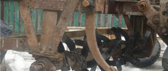
According to the method of soil cultivation, homemade motor cultivators are either self-propelled, equipped with driven wheels, or with a rotating working attachment, which can be used as a means of movement.
The first option uses two gearboxes. The first helps the mechanism move at a given speed, and the second rotates the rotary attachment for cultivating the soil. If there are drive wheels, the cultivator is additionally equipped with flat-cutting knives.
There are also simplified homemade products, where the wheels only rest on the surface, making movement easier.
From the starter
If you have an unnecessary starter from a car in your home workshop, you can use it to create a primitive version of a motor cultivator. To do this, you need to shorten its shaft and slightly alter the front cover, making several holes in it with a diameter of up to 5 mm. This is necessary for the flow of air from the ventilation system. Then the prepared starter is combined into one unit with cutting elements (cutters).
The almost finished installation is fixed onto the working platform of the cultivator and checked for functionality. You can make an electric cultivator with your own hands from a starter in a couple of hours and with minimal financial costs.
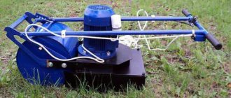
From the Bulgarian
The homemade version of a mini-cultivator made from a grinder is not very productive, but it perfectly solves the problem of weeding a small area with light soil. The grinder in this homemade invention plays the role of an electric drive. The remaining components and parts can be taken from an old non-working cultivator.
A grinder is attached to a frame created from improvised means or taken from an old frame, as well as an extension cord on a reel for connecting to a source of electricity.
After assembling the main elements, you can test the machine. If everything is done correctly, the cutters will produce up to 300 rpm.
Homemade Cultivator From a Drill
The winch acts as a traction horse pulling a cultivator, plow, hiller, harrow, potato digger, or something else. And the first thing is that the gaming slots in front of the cultivator have. it's multifunctional. The winch is installed on the edge of the cultivated area, the cultivator attached to the winch, or the plow, goes to the opposite side of the area, unwinding the winch, then the winch is turned on, pulling the cultivator or plow, which do their job. When the cultivator or plow reaches the winch, it turns off, moves to the side and the process repeats. And the entire area is processed in this manner.
In such a homemade electric cultivator (or an electric plow, depending on what the winch is pulling) there is an element of any complexity. this is a winch. There are enough options for producing a winch, but they have three main components: an engine, a gearbox and a drum (reel) with a cable.
Approximate motor power 1.5-2.5 kW (preferably more than 3.5 kW), number of revolutions. 1500 rpm If the motor power is not sufficient, it will be impossible to cut deeply into the ground with the plow, or you will have to move the plow at a low speed. If the engine has enormous power, then in addition to the unjustified energy consumption, the winch will turn out to be more arduous and will have to be constantly moved. Naturally, you can not limit yourself to electric motors; an internal combustion engine is also used, for example, from the correct selection of a motor cultivator.
Gearbox. This is the most problematic component of the entire electric cultivator (electric plough). The best option is when there is a gear motor with a good output shaft speed. It would be great if there was at least a factory gearbox. And it’s completely bad if there is neither the first nor the second, then you will have to hiccup and select gears, although this is the simplest option. This is a worm gear, one worm (screw) and one gear (helical wheel) is enough, in cases where the gear ratio is not large enough, of course it can be additionally increased by a belt drive between the engine and the worm. You will have to make an additional belt drive and if the passage if the factory gearbox does not have the best gear ratio, or to connect the engine to the gearbox. The best gear ratio is calculated using the usual formula:
where i. gear ratio; D. the diameter of the drum what rope is wound (m); n. engine speed (rpm); V. speed of movement of the cultivator on another plow (m/min).
It is better to focus on the speed of movement of the cultivator (plough) equal to 4 km/h. slow step. Let the diameter of the drum be 15 cm, more about this below. We convert the numbers into a suitable dimension (4 km/hour = 67 m/min, 15 cm = 0.15 m) and substitute them into the formula:
It turns out that with an engine with a rotation speed of 1500 rpm, a not entirely huge gear ratio is required. To obtain it, it is not at all necessary to use only gear or worm gears.
A reel that winds a cable with a cultivator or plow. This is the most common element of a winch, but almost everything depends on its size. The smaller the diameter of the coil, the slower the cultivator (plow) will move, therefore, when it is not possible to make the best gear ratio, and the speed of the cultivator (plough) is very high, there is an option to reduce the diameter of the coil. Reducing the diameter by half will lead to a decrease in the speed of the cultivator (plough) also by half. You can also use a reduction in the diameter of the coil when the engine power is low, for example, when plowing virgin soil. But with a small diameter of the coil, the cable becomes more entangled. Today, with a small diameter of the coil upon completion of winding the cable, the diameter of the coil increases faster, which leads, on the positive side, to the acceleration of the cultivator (plough), and on the other hand, to an increase in the load on the engine. Therefore, a coil with a small diameter must be made longer, so that there is more than just room for the cable. Unfortunately, lengthening the reel makes it difficult to lay the cable evenly when winding it; the most common solution to this problem is demonstrated in the video below. Just as a decrease in the diameter of the coil leads to a decrease in the speed of the cultivator (plough), with an increase in the diameter the speed increases. This is used if the gearbox has a very large gear ratio, due to which the coil rotates very slowly. There are options with a reel diameter of 30 cm. To prevent the winch from tipping over, the entire structure should be located closest to the ground, and the cable, especially with a larger reel diameter, should be wound onto the reel from below.
To unwind the winch, different methods are used, for example, running the motor in the opposite direction or a disconnecting coupling between the gearbox and the reel.
To make the winch stable, stops are made to cut into the ground if it is heavy. wheels. It is stylish to make a seat on the winch for an assistant, who with his weight will give it great stability.
It is better for two people to work with such an electric cultivator (electric plow), one walks with the plow over the other cultivator, and the other turns the engine on and off and controls the winch unwinding mechanism. It will be easy to move the winch with two people. The winch should be positioned so that the axis of rotation of the reel is aimed strictly perpendicular to the direction of movement of the cultivator (plow), so the cable will be wound more evenly. When working with a plow, it is important to change the placement of the winch from year to year, placing it on the opposite end of the cultivated area, this will prevent the gradual movement of the earth due to its dumping by the plow and dragging it to the winch.
If you have any doubts regarding the effectiveness of such an electric cultivator (electric plow), after watching the video they will probably be dispelled. And again, let us remind you that not only a plow or cultivator is attached to the winch, but also an additional hiller, harrow, potato digger, etc.
Electric plow Motor plow Electric plow Motor plow and hiller from motor winch Burlak Source