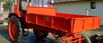
Along with all systems, the MTZ 80 tractor is equipped with pneumatic equipment, which expands the functional qualities of the machine. The pneumatic system of the MTZ tractor is designed to drive the brakes of the chassis of trailed equipment and vehicles, as well as to extract compressed air when inflating tires or using pressure when servicing the tractor.
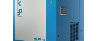
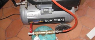
Compressor on the engine of the MTZ 80 tractor
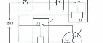
Tractor pneumatic system
In operating condition, the system automatically maintains operating pressure in response to a set upper limit value or to a pressure drop as a result of the operation of the brake drive and compressed air extraction.
The system includes:
- Compressor - a unit that creates air pressure
- Air tank receiver
- Pressure regulator - a unit that regulates pressure in the system
- Pressure gauge - system control instrument on the control panel
- Brake valve - a unit designed to control the supply of pressure to the working pneumatic cylinders of the trailer brakes. The crane control drive is interlocked with the tractor brake pedals.
- Disconnect valve - a unit for opening and closing pressure in the connecting pneumatic pipeline.
- Pneumatic adapter is a device for driving the brakes of trailer vehicles with a hydraulic braking system.
- The connecting head is a coupling for connecting the air lines of the tractor and trailer.
Diagram of the MTZ 80 pneumatic system
The working pressure created by the compressor in the pneumatic system of the Belarus tractor is maintained automatically by the regulator within the range of 6.5-8 kgm/cm² (6.7-7.3 in earlier versions of the tractor). The safety valve is activated when the pressure rises in the range of 8.5-10 kgm/cm² (8.5-9 in earlier versions). If the system is working properly, the pressure drop within half an hour after stopping the engine should not exceed 2 kgm/cm². If the drop value increases, the pneumatic system must be checked and then troubleshooted.
Brake system diagram
Before you begin adjusting or repairing this important unit, it is advisable to study the diagram of its structure. With its help, you can find out what the MTZ 82 brake system is, get acquainted with the features of its design and operating principle. This will allow the technician to avoid mistakes when performing maintenance on his own.
Brake device
Tractors in this series are equipped with a dry-type brake system, the main element of which is special discs. They are placed symmetrically on the key shafts, thereby stopping their movement if necessary. To protect such important parts from mechanical damage, durable casings are used, which increases the service life of the disks.
Studying the MTZ 82 brake design in more detail, it is necessary to highlight several key components that deserve mention. Among them:
- brake discs combined with each other using connecting units;
- friction linings placed on disk mechanisms;
- 2 pressure disks, which are connected to the brake counterparts, are made of high-strength cast iron.
The design of the element provides for the presence of several expanding spherical elements, evenly distributed around the circumference between the disk mechanisms. Special recesses are used to fix them, which ensures correct operation of the unit.
The brake system is reliably protected from the ingress of various substances, for example, lubricants, that can impair their functionality. A glass with cuffs is used as a protective element that does not allow leaks, and its lid is equipped with a rubber seal.
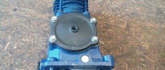
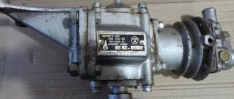
Design and operation of the compressor
The single-cylinder piston unit is installed on the left side of the tractor on the diesel timing gear housing. The compressor receives its drive from the gear of the high-pressure fuel pump when rotation is transmitted through the intermediate gear to the driven gear, the teeth of which are integral with the crankshaft of the unit.
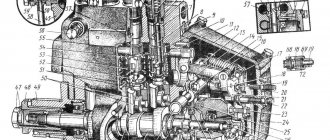
node device
The drive is turned on at the immediate location of the unit using a handle that engages the intermediate gear with the injection pump gear. Turning the handle to the extreme right position corresponds to the drive being turned on, and turning the handle to the left corresponds to being turned off. Switching on is carried out when the diesel engine is not running or, in extreme cases, at minimum speed.
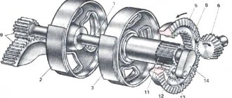
The unit is a single-cylinder piston mechanism, the crankshaft of which is located in a separate cast-iron crankcase. The shaft rests with its edges on ball bearings installed in the walls of the housing. An oil pipeline from the diesel lubrication system is connected to the side cover of the crankcase, together with the support of the crankshaft rotation axis. Through this line, the lubricant flows through the crankshaft channel of the unit to the rubbing surfaces of the crankpin bearings and then splashes to all parts of the piston group and drive mechanisms, then flows from the crankcase down into the housing of the diesel timing gears.
A cylinder in the form of a casting with heat-dissipating fins for cooling, assembled with a head, is attached to the crankcase with four studs through a gasket. The cylinder head houses a valve mechanism consisting of plate inlet and discharge valves. The spring design principle ensures the opening of the discharge valve during the compression stroke of the piston movement, increasing the potential of air pressure in the system, and the opening of the intake valve under the influence of vacuum when the piston moves to the lower position.
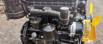
Specifications
The compressor with catalog number A 29.01.000 is equipped with tractors with engines D-240, D-243, D-245.
- Type - single cylinder
- Cooling - air
- Cylinder diameter -72 mm
- Working volume - 155 cm³
- Piston stroke - 38 mm
- Productivity - 115 l/min.
- The nominal rotation speed is 1350 rpm.
- Maximum rotation speed - 1550 rpm.
- Unit weight - 9.5 kg
Brake Maintenance
In order to repair the brakes of this tractor model as rarely as possible, you should regularly carry out maintenance of this unit, and also follow the general recommendations for working with it. It is not recommended to clamp the pedals unless absolutely necessary, as this leads to increased wear of the friction linings. You should also adhere to other rules:
- stopping should be carried out smoothly, until the final position of the pedal;
- after use, it is necessary to remove the pedal latch to avoid damage to the mechanisms when starting to move;
- inspection of the main structural parts should be carried out daily.
You should also familiarize yourself in more detail with the procedure for adjusting the brake mechanisms, since it is often required for the correct operation of the unit. If you watch a video on how to adjust the brakes on the MTZ 82, the manipulations will be much easier and more convenient. To adjust, you will need to remove the lock nuts of the bolts, and then screw them into the adjusting forks in such a way as to restore normal pedal travel. After this, it is enough to install the dismantled elements and tighten them for reliable fixation.
MTZ Fans Club. Page 157 of 215
Questions can only be asked after registration. Please login or register.
you need to write to the administrator
To the editor. Please change my nickname to (as it was, just stick a dot somewhere, for example.) Because the old one is 100% more problematic.
Guys, the neutral is gone, only 1 and the rear turn on, the shift lever is on the right. Has anyone had it, what could it be?
Guys, the neutral is gone, only 1 and the rear turn on, the shift lever is on the right. Has anyone had it, what could it be?
How can you tell if neutral is lost and won’t shift to other gears?
The problem was due to the corkscrew pin, it came out half a ml. and the splined shaft jammed!
The problem was due to the corkscrew pin, it came out half a ml. and the splined shaft jammed!
I see, but I thought this leash had broken.
hi guys! this is the case! on 1025 some kind of horseradish, the oil filler neck is covered in oil during operation and a little bit of the hose from the breather, the piston rings are new! I went through the run-in, even though I didn’t even take a liter, and then I drove around in the middle of the row and such crap, although it was warming up at 60-70 degrees! I've already checked the breather is clean!
t-150k(D-260.4), MTZ-80, MTZ-1025!
hi guys! this is the case! on 1025 some kind of horseradish, the oil filler neck is covered in oil during operation and a little bit of the hose from the breather, the piston rings are new! I went through the run-in, even though I didn’t even take a liter, and then I drove around in the middle of the row and such crap, although it was warming up at 60-70 degrees! I've already checked the breather is clean!
Hello colleague. Perhaps the volume of oil in the pan increases due to mixing with air. Due to a crack in the oil pump tube or other leak in the lubrication system.
Hi all. A question. I bought an MTZ 50. The engine is 80, it throws oil into the muffler, but the breather is dry. What is the reason? The oil pressure when cold is 4, and when hot it is almost 0. Will replacing the liners help me raise the pressure to at least 1.5.
How does the MTZ-82 brake system work?
The brakes on the MTZ-82 operate as follows. When you press the brake pedal, the special brake rods of the cushions move down, thereby turning the roller and levers. After this, the force is transmitted to the forks using spherical washers and bolts. Using traction and fingers, they are firmly attached to the pressure plates. Under the influence of traction, these disks unfold and thereby move the spheres along inclined surfaces, and the disks expand.
Using the same discs, the linings located on the connecting discs are pressed against the cup cover and the brake casing. After this, the key gear wheels responsible for the final drive slow down, and the tractor wheels stop. The pedals and discs are brought to their original position by the action of special springs and pressure discs.
When braking, all wheels can stop either simultaneously or separately.
In this case, the technique of applying different influences on two pedals is used if it is necessary to provide the tractor with additional maneuverability. Be careful, because you should not allow a single wheel of agricultural machinery to brake when the machine accelerates at more than a speed of 10 km/h. This is dangerous because it can ultimately cause the machine to tip over. In order to simultaneously use the right and left brakes, it is necessary to lock both pedals using the connecting bar. The mode in which all wheels stop at the same time is standard, which is why it is necessary to constantly ensure that the pedals are locked.
The design of the MTZ-82 brakes assumes that the tractor driver can fix the pedal in the braking state. A similar action can be performed using a special latch equipped with teeth, which is controlled by the thrust acting on it. The traction, in turn, is affected by a handle, which is installed near the right wall of the driver’s cabin. When using the handle, the latch is rotated to the desired position and secured to the stop, which is located on the lever of the desired pedal.
If you work on slopes or in slippery road conditions, then in order to achieve better braking, experts recommend manually engaging the front axle.
In order to ensure a long service life for the brake system, the following rules must be followed:
- Do not press the brake pedal unless necessary. This will lead to rapid failure of the friction linings.
- Brake smoothly, pressing the brake fully and not fixing the pedal at any intermediate level.
- Disengage the clutch when braking.
- Do not forget to remove the latch that holds the pedals in the brake position when you begin to set the Minsk modification tractor in motion.
How to adjust the brakes of MTZ-82
Let's look at how the brakes are adjusted. There are often cases when a farmer has a question about why the brakes on the MTZ-82 jam. The problem may lie in non-compliance with the above rules. Brakes need to be inspected regularly, preferably daily. If you see that something is wrong with them, you need to make adjustments.
Absolutely any tractor driver can adjust the brakes independently. You can understand that they need adjustment by looking at the length of the braking distance and the full travel of the pedal. The full stroke should be about 90 mm. If you understand that the pedal does not travel that distance and is sticking, then this is a reason to resort to adjustment.
Adjust the pedal travel as follows:
- Remove the lock nuts of the bolts and screw them into the adjustment forks until the pedal travel becomes acceptable.
- Install and tighten the locknuts.
Regulatory actions, as mentioned above, must be carried out regularly when the need arises. The brake check should be performed on a flat, dry area. Typically, at a vehicle speed of 30 km/h, the tractor braking distance should be no more than 10 m from the moment the pedal was pressed.
To understand whether both sides of the wheels are braking evenly, it is enough to look at the marks that the tractor left on the ground after the equipment was stopped. The unevenness should be no more than 1 m along the entire trail. If you see that one of the sides is lagging, adjust the travel of the pedal responsible for that side. Please note that braking may be uneven due to oil leaking into the brake system and onto the brake linings.
The design of brakes in the MTZ-82 tractor and recommendations for operation
Farmers are interested in how to adjust the MTZ-82 brakes, the design of which they would like to know better. Brakes for Minsk Tractor Plant products, including equipment such as the MTZ-82 mini-tractor, are needed so that the tractor driver can reduce the speed of movement, completely stop the agricultural machinery and keep it stationary when required. In addition, the braking system can allow you to maneuver more efficiently and take tight turns when necessary.
Brake device MTZ-82
The Belarus tractor is usually equipped with dry disc brakes. They are installed on the shafts of the key gear wheels. They stand on both sides, and special protective covers are placed on top of them.
The MTZ-82 brake system consists of several elements:
- Two connecting disks, which are combined with the help of special devices with the final drive gears.
- Friction linings glued to discs.
- A pair of pressure plates, which are made of cast iron material and are connected to the first structural element.
Between the last elements, several expansion balls are installed, which are positioned along the entire circumference with equal distances from each other. These balls must fit into special inclined sockets, which are made from the inside on the pressure disks. Inside, the design of the tractor brakes is completely protected from the leakage of oil contained on the rear axle. The protection is made by installing a special pair of self-clamping cuffs on the lid of the glass. The lid, in turn, receives a seal with a rubber ring.