How does a Belarus tractor air compressor work? How does it function? Nuances of service.
A modern tractor has a rather complex structure and consists of a large number of parts, components and assemblies, each of which performs its own set of functions and tasks. And the MTZ compressor is one of such devices, used to convert mechanical energy coming from the motor into compressed air, which is used to power certain on-board systems and ensure the functioning of the braking system on towed devices. Let's look at this element in more detail.
Compressor device
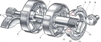
Structurally, a tractor compressor resembles a conventional internal combustion engine. The basis of its design is also a cylinder, a piston and a crankshaft. However, the movement of the cylinder is imparted by a rotating shaft, which receives torque from the tractor engine, namely from the fuel pump gear through the intermediate gear and the gear on the compressor crankshaft.
Main elements of the unit:
- crankshaft;
- cylinder;
- cylinder head;
- piston group;
- crankcase;
- discharge and air intake valves.
Both valves, discharge and air intake, are plate type. The valves are located on top of the unit and are equipped with springs that press them to the seats.
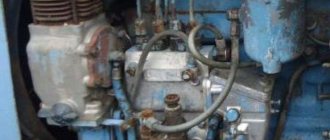
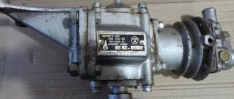
The compressor is located on the left side of the engine distribution cover. To ensure air cooling, the case is made in the form of a radiator. Oil for lubrication of parts is supplied from the main oil line by splashing.
Specifications
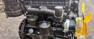
MTZ 80 and 82 tractors are equipped with D240 and D243 diesel engines, together with which MTZ compressors model A29 01.000 operate.
The device provides constant pressure in the system at 0.6 MPa. The characteristics of the compressor ensure reliable operation and ease of maintenance - it is quite possible to repair the unit alone and outside a specially equipped workshop.
Characteristics:
- Crankshaft speed 1350 rpm.
- Capacity 115 l/min.
- Cylinder displacement – 172 cubic meters. cm.
- The piston stroke is 38 mm.
- Cooling is air.
- Power – 2 kW.
- The MTZ compressor head is an old model.
- Weight – 8 kg.
Be sure to read: What is the difference between a gear starter and a regular starter?
Not available:
| № | Part code | Name | Part Information |
| 240-3509030-A | Installation of a pneumatic compressor | Quantity 1 Model 240 Group Brakes Subgroup Air brake compressor Serial part number 030 Additionally Interchangeable with a part previously released under the same number | Not available |
| A29-05-000-B3A | Pneumatic compressor | Quantity 1 | Not available |
| M10-6gx45 | Bolt | Quantity 1 | Not available |
| М10-6Н | screw | Quantity 3 | Not available |
| 1065G06 | Washer | Quantity 3 | Not available |
| 36-1104788 | Pad | Quantity 3 Model 36 Group Engine power system Subgroup Fuel pipelines Part serial number 788 | Not available |
| 240-3509232 | Union | Quantity 1 Model 240 Group Brakes Subgroup Air brake compressor Part number 232 | Not available |
| 240-3509158 | Clamp | Quantity 1 Model 240 Group Brakes Subgroup Air brake compressor Part number 158 | Not available |
| 240-3509159 | Bracket | Quantity 1 Model 240 Group Brakes Subgroup Air brake compressor Part number 159 | Not available |
| M6-6gx16 | Bolt | Quantity 1 | Not available |
| М6-6Н | screw | Quantity 1 | Not available |
| 665G06 | Washer | Quantity 1 | Not available |
| RD18-29-300-1.3 | Sleeve detail | Quantity 1 | Not available |
| XC-26-019 | Clamp | Quantity 2 | Not available |
Operating principle of the device
The compressor works according to the following principle:
- A running engine transmits torque to the compressor crankshaft.
- The piston rises until it reaches TDC (top dead center) and compresses the air until the injection valve opens.
- Air flows from the motor suction manifold until the pressure reaches 7.4 kgf per square meter. cm.
- The regulator stops supply until the pressure drops to 6.6 kgf/sq.m. cm.
- When this indicator is reached, the regulator operates again, the valve opens and the cycle repeats. The pressure in the tractor pneumatic system is maintained at the required level.
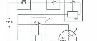
Tractor pneumatic system
In operating condition, the system automatically maintains operating pressure in response to a set upper limit value or to a pressure drop as a result of the operation of the brake drive and compressed air extraction.
- Compressor - a unit that creates air pressure
- Air tank receiver
- Pressure regulator - a unit that regulates pressure in the system
- Pressure gauge - system control instrument on the control panel
- Brake valve - a unit designed to control the supply of pressure to the working pneumatic cylinders of the trailer brakes. The crane control drive is interlocked with the tractor brake pedals.
- Disconnect valve - a unit for opening and closing pressure in the connecting pneumatic pipeline.
- Pneumatic adapter is a device for driving the brakes of trailer vehicles with a hydraulic braking system.
- The connecting head is a coupling for connecting the air lines of the tractor and trailer.
The working pressure created by the compressor in the pneumatic system of the Belarus tractor is maintained automatically by the regulator within the range of 6.5-8 kgm/cm² (6.7-7.3 in earlier versions of the tractor). The safety valve is activated when the pressure rises in the range of 8.5-10 kgm/cm² (8.5-9 in earlier versions). If the system is working properly, the pressure drop within half an hour after stopping the engine should not exceed 2 kgm/cm². If the drop value increases, the pneumatic system must be checked and then troubleshooted.
Compressor dismantling
Dismantling procedure:
- Disconnect the suction and discharge hoses and the oil line of the MTZ compressor.
- Unscrew the three nuts and the mounting bolt.
- If it is necessary to inspect the valves, unscrew the fitting and plug, then remove the valve body and spring.
No special tools are required for dismantling; a regular kit, which includes screwdrivers, wrenches of various sizes and pliers, is sufficient.
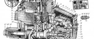
Compressor circuit
Possible malfunctions and repairs
As a rule, problems with the pneumatic system become noticeable when the proper pressure is not provided. The reasons can be different, from slipping of the drive belt to mechanical wear of components. Defective spare parts, poor-quality and untimely maintenance, climatic parameters and working conditions (for example, high humidity or dust in the air) and much more can also play a role.
Main symptoms of problems:
- A complete lack of pressure may be due to faulty valves or slippage of the drive belt. First, you should replace the belt; it's easy and quick. If the belt is new and installed correctly, then the problem is in the compressor device itself. In particular, you need to inspect the discharge and suction hoses of the MTZ compressor and make sure that they are not damaged and are properly secured.
- The wear of the valves is immediately visible - the parts are bent and crumpled. Double-sided parts can be turned over (provided the second surface is not worn). If replacement is unavoidable, new valves must be ground in. This is done like this: you need to apply lapping paste to the disk and intensively rotate it along the seat. The easiest way to perform this operation is to use a drill with a pre-attached rubber hose. After grinding in, the disc must be washed in kerosene or diesel fuel. It is necessary to check the springs and change them if necessary.
- Low pressure most often means excessive wear of the rings and piston group. This is also indicated by an increased amount of oil in the condensate. The piston rings and crankshaft seals need to be replaced. All necessary materials are included in the MTZ compressor repair kit, which can be purchased at any auto parts store (including online).
- If extraneous sounds appear in the piston area, you should suspect surface wear. Usually it is enough to listen carefully to where and at what moment the knocking occurs in order to understand which part is worn out.
- A knocking sound in the crankshaft indicates that the bearings or bearings are damaged. The problem is solved by replacing the crankshaft journal needle bearing or connecting rod bearing shells. The bearing itself is changed only if there is play in the upper head of the connecting rod in a plane parallel to the crankshaft axis.
- Most problems can be determined independently by disassembling the compressor. However, for a complete diagnosis, measurements will be required. The internal diameter of the cylinder should be 72 mm (measured with a bore gauge). The outer diameter of the piston skirt should be 71.87 mm. The gap between the ring lock in the cylinder should be no more than 1.21 mm. To measure gaps, special feeler gauges are used.
Be sure to read: Installation of a crane beam for a garage
Stages of assembly work
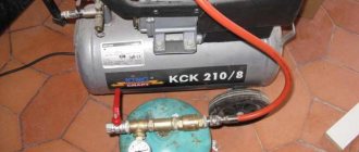
Making a compressor from a refrigerator means following a simple sequence of steps:
- Take pliers, a 12mm spanner, 2 screwdrivers - one for plus and one for minus. At the bottom of the rear panel, use pliers to cut through the tubes connecting the compressor to the cooling system. Unscrew the start relay, having previously marked the top and bottom sides on it. Disconnect the relay from the plug. We take all the fasteners with us.
- Checking functionality: reconnect the relay, provide air access to the compressor through the tubes, connect to the network. If everything is done correctly, the device works. Air will flow into one tube and out of the other. Label these tubes.
- Attach the compressor with self-tapping screws to a wooden board.
- We take an old fire extinguisher, 1 hose 600 mm long, 2 others - 100 mm, fuel filter, clamps, pressure gauge, sealant. We already have a drill, a screwdriver, and pliers.
- If there is no fire extinguisher, then we will make a plastic container. To do this, you need to take a container with a volume of more than 3 liters. Make 2 holes. Insert the inlet tube into 1 hole at a distance of 2 cm from the bottom of the container. We lower the outlet pipeline 10 cm deep. It is impossible to install a pressure gauge on a plastic tank.
- If there is an iron tank, then the tubes can be fixed by welding. We install a pressure gauge on the iron receiver. We fasten the receiver and compressor together.
- Place a filter on a 10 cm long hose and attach the free end of the tube to the inlet of the constructed apparatus. We use another hose to connect the receiver inlet to the compressor outlet. We fix the joining places with clamps. A diesel filter is attached to the last hose, and its free end is inserted into the outlet of the receiver. If necessary, equipment can be attached to the remaining end of the tube to make airbrushing and painting available.
Second version of step-by-step instructions:
- We drill a special hole for the adapter that needs to be secured. You can choose different methods, for example, the most affordable is cold welding (using Epoxylin).
- Carefully clean the bottom of the receiver from contaminants - plaque and rust. This is necessary so that Epoxylin adheres well to the surface for strong bonding. And, of course, so that the paint does not become dirty and does not form into lumps with debris. This can be achieved by sanding the bottom of the fire extinguisher to a metallic shine using rotating and circular movements using sandpaper.
- We secure the adapter by clamping it from the front side with a nut, and give the Epoxylin time to harden according to the instructions.
- Let's move on to the base for the compressor, for which you need to acquire three wooden boards or a piece of plywood measuring 30 by 30 cm. For the convenience of further moving our device, you can screw mobile furniture wheels to the base. We do not specifically describe the dimensions of the holes and other details, since this will all be purely individual, as it depends on the selected material, type of compressor, and so on.
- We drill holes for the compressor and studs and mount them. The studs are secured with nuts and washers. We put a car filter with a special paper core on the inhalation of the compressor. This will help prevent dust and other small contaminants from getting inside the compressor.
- Next we'll deal with the electrical work. To make our homemade compressor for painting a car convenient to use, we equip it with a pressure switch (for example, PM5 or RDM5), as well as a shutdown switch. The first device, a pressure switch, is necessary for us to turn off the compressor during the process of pumping air into the receiver, when the pressure reaches the permissible maximum, and vice versa, to turn it on when the pressure drops below the permissible minimum. You can set the values of the maximum and minimum pressures directly on the relay using springs, with the large spring responsible for the minimum pressure (and the corresponding activation of the compressor), and the small one for the difference between the maximum and minimum pressure values.
- Take a closer look and you will see 2 contacts on the relay, designed specifically for connecting it to the network. Since such relays were originally used in the water supply system, we will slightly change its purpose and connection features. Our task is to connect the first contact to the network, and the second to the compressor.
- We place the general shutdown switch on the gap between the pressure switch and the 220V network. This will help de-energize the entire installation so that you don’t have to constantly run around to turn it on and off.
- We paint the receiver and begin final assembly.
- Screw the nut with the fitting onto the oil-moisture separator filter.
- We take the hose and put one end of it on the fitting, and with the other we pull it onto the compressor tube and clamp it all with clamps. To do this, we take a reinforced, oil-resistant hose. Each threaded connection should be sealed with fum tape.
- We screw the filter to the bottom of the receiver and treat the silicone connection with sealant.
- We screw on the cast iron lid, but pre-treat its threaded connection with the same sealant. To improve sealing, you can place a rubber gasket under the lid.
- You need to screw a tube onto the lid, the thread of which should be a quarter of an inch, and screw the cross onto it.