Overhead crane
- This is a special structure that has an above-ground location and is used in construction and industrial production for lifting and moving various loads and equipment. Due to its simplicity of execution, this mechanism is in wide demand. It is used not only in production workshops, but in warehouses, as well as during installation and construction work.
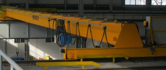
The most common lifting equipment in industries such as metallurgy and mechanical engineering is an overhead crane. Its design features make it possible to make full use of production premises and move loads from 1 to 20 tons throughout them. It moves freely back and forth and left and right, and since its main part is located in the upper tier of the workshops, it does not take up much space.
Types and classification of overhead cranes
Several types of cranes are used in industrial areas; their classification depends on the design features and type of fastening.
Based on their component mechanisms, they are distinguished:
- Single girder overhead crane. It is also called a “beam crane”, since it consists of one I-beam, at the ends of which there are end beams with attached running wheels. Such cranes are lightweight and can move a load of up to 10 tons, lifting it to a height of no more than 18 meters.
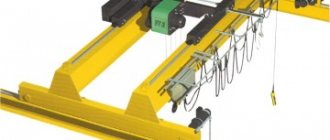
- Double girder overhead crane. This type is more common than the previous one; its design difference consists in the movement of the hoist along two beams, and not along one. The trolley can be modernized and have an auxiliary mechanism instead of one. This type has a large lift; the overhead crane is controlled from its cabin, and in some models, by remote control.
Depending on the fixation, there are types:
- Overhead overhead crane. The trolley of the device “walks” along the top of the beam, resting its wheels on the crane rails. This design is the most reliable and has a high load capacity.
- Suspended bridge crane. It is suspended from the bottom of the beam, this is an economical option, but it is not as reliable as the previous one.
Construction of a double girder overhead crane
The main design feature of a double-girder crane, which distinguishes it from other types of cranes, is a bridge consisting of two beams of a box or lattice structure. The bridge beams rest on two transverse end beams (trolleys), on which the running mechanism of the forklift is installed. Thanks to it, the machine moves along the rails of crane tracks in the upper belt of a workshop or overpass located in an open area. Crane tracks are attached to columns (or other load-bearing structures of the building) or to external ground supports.
The lifting and lowering of the load is carried out by a mechanism mounted on a cargo trolley moving along the crane bridge. The design of the trolley is a welded frame on which one or two lifting mechanisms (telphers) are mounted, as well as a movement mechanism, the low-speed shaft of which evenly transfers the load to the running wheels of the trolley. In this case, the PMG of the trolley can have an expanded (all parts are mounted on the trolley separately) or a modular layout (the PMG is mounted on the assembled trolley).
If an electric double-girder overhead support crane is designed to work with long loads, 2 load trolleys can be installed on it, the operation of the mechanisms of which must be synchronized.
The gear motors driving the forklift are synchronized. Power is supplied to them using a trolley busbar, and to the mechanisms of the cargo trolley - using a flexible cable suspension. The double girder support crane is controlled from the cabin or from the floor using a wired or radio remote control.
Technical characteristics of overhead cranes
At the heart of any of their types is a bridge (double or single beam), on which a cart “walks.”
Main nodes:
- Brakes serve to hold the container and stop the bridge in the desired position.
- Mechanism for capturing cargo. It can be either one or several at once. Its components are: shafts, electric motor, cargo cables and gearbox.
- Crane tracks, which ensure the movement of the crane beam and guarantee uniform redistribution of the load.
All mechanisms are controlled from the cabin, and if the overhead crane is manual, then from a remote control, which may be located outside the workshop area.
General characteristics are given in the table.
| Indicators | Meaning |
| Speed | from 8 to 60 m/min |
| Operating mode | up to A5 |
| Overhead crane lifting capacity | from 1 to 20 tons |
| Temperature | from -40 to +40 degrees |
| Conduit | closed or open trolleys, flexible cable |
| Speed Options | 1,2,3,4 |
GOST 534-78 Overhead overhead cranes. spans
STATE STANDARD OF THE USSR UNION
BRIDGE SUPPORT CRANES. SPANS
GOST 534-78 (ST SEV 5235-85)
USSR STATE COMMITTEE ON STANDARDS
Moscow
STATE STANDARD OF THE USSR UNION
| BRIDGE SUPPORT CRANES. SPANS Overhead traveling cranes. Spans | GOST 534-78* (ST SEV 5235-85) Instead of GOST 534-69 |
By Decree of the USSR State Committee on Standards dated August 17, 1978 No. 2234, the introduction date was established
from 01.07.79
Verified in 1983. The validity period was extended by State Standard Decree 02.09.83 No. 4127
until 07/01/89
Failure to comply with the standard is punishable by law
* Reissue (July 1986) with Changes No. 1, 2, approved in September 1983, April 1986 (IUS 12-83, 7-86).
1 . This standard applies to overhead support cranes (hereinafter referred to as cranes) of all types and lifting capacities, intended for operation in buildings with spans up to 36 m, as well as on open crane trestles.
The standard corresponds to ST SEV 5235-85.
(Changed edition, Amendment No. 2).
2. Crane group depending on lifting capacity and size l
indicated in the drawing should be determined from the table. 1 .
Table 1
| Group | Load capacity | l , mm, no more |
| 1 | Up to 50 incl. | 300 |
| 2 | Over 50 to 125 incl. | 400 |
| 3 | St. 125 | 500 |
(Changed edition, Amendment No. 2).
3. Crane spans L
k indicated in the drawing must correspond to those given in the table. 2.
table 2
| Building spans L | spans L for group cranes | |||
| 1 | 2 | 3 | ||
| in the absence of passages along the crane tracks | in the presence of passages along the crane tracks | |||
| 6 | 4,5 | — | — | — |
| 9 | 7,5 | — | — | — |
| 12 | 10,5 | 10 | 10 | 10 |
| (15) | (13,5) | (13) | (13) | (13) |
| 18 | 16,5 | 16 | 16 | 15,5 |
| (21) | (19,5) | (19) | (19) | (18,5) |
| 24 | 22,5 | 22 | 22 | 21,5 |
| (27) | (25,5) | (25) | (25) | (24,5) |
| 30 | 28,5 | 28 | 28 | 27,5 |
| (33) | (31,5) | (31) | (31) | (30,5) |
| 36 | 34,5 | 34 | 34 | 33,5 |
Note: The dimensions indicated in brackets are not recommended.
4 . Cranes intended for operation in unique, experimental and reconstructed buildings, on open overpasses and in buildings built according to designs approved before July 1, 1970, are allowed, by agreement between the consumer and the manufacturer, to be manufactured with spans corresponding to the spans of the specified buildings and overpasses, and cranes intended for export - with spans in accordance with the orders of the foreign trade organization.
(Changed edition, Amendment No. 1).
5 . The spans of electric overhead cranes with a lifting capacity of up to 12.5 tons inclusive and manual overhead cranes of all lifting capacities can be increased by 0.5 m, if the dimensions of the columns allow this.
6. The spans of overhead cranes specified in this standard may be reduced by a multiple of 0.5 m:
in buildings with a crane runway height from the floor level of more than 10 m;
for the lower crane when the cranes are located in one span in two tiers;
if there is a wall located along the middle row of columns, and it is necessary to create passages along the crane runways on both sides.
For size l
more than 550 mm.
Purpose and application
The overhead crane devices in question are used in large enterprises, sometimes in small auto repair shops. The machines are used for various loads in the foundry industry, mechanical engineering and construction work, in the oil refining and chemical industries.
Purpose of the overhead crane:
- lifting loads in indoor areas and carrying them;
- work with bulk goods, for which models with grabs are used;
- carrying out lifting operations without current;
- operations at closed and open sites.
Overhead cranes help large enterprises operate, which allows them to conquer new markets.
Scope of application
Thanks to their exceptionally reliable and safe design, double girder cranes are widely used:
- in open areas of large warehouses, large cargo terminals,
- during the construction and installation of large-scale facilities,
- in foundries of metallurgical enterprises,
- in assembly shops of factories producing large-sized equipment and machine tools,
- in workshops and warehouses of large enterprises in the food, chemical and pharmaceutical industries, incl. in fire and explosion hazardous industries.
In other words, double-girder cranes are in demand where large and long loads need to be moved, as well as increased requirements for the reliability and stability of the lifting mechanism. It is the load capacity and the length of the span beams that are the two main criteria on the basis of which double-girder support cranes are selected.
These PMGs can operate in difficult climatic conditions, in enterprises with an aggressive environment and high temperatures - in the chemical, oil refining, forestry, metallurgical industries, at airports, shipyards, and military bases.
Installation
Installation of a double-girder overhead crane is carried out taking into account the following indicators:
- Technical characteristics of the crane (weight, maximum lifting height, overall dimensions, installation diagram).
- The dimensions of the room or workshop, the load-bearing capacity of the walls or columns on which the crane runways will be installed.
- Conditions for assembling the structure (availability of access roads and installation site).
There are several methods for assembling a crane. Single-beam lightweight structures are mounted below. Then the finished structure is lifted up using auxiliary equipment and installed on the rails. Installation of the structure involves a large number of operations, especially when assembling devices with a load capacity of 50-100 tons and above.
Installation stages of a double girder crane:
- Half-bridges are being installed. At the assembly site, 2 halves of the bridge are assembled.
- The end beams are assembled and installed on the crane runway.
- The half-bridges are lifted and installed on the ring beams.
- Half bridges and end beams are connected to each other.
- The trolley movement system is being installed. Then they lift it and fix it on the bridge.
- The power supply unit and the device control system are assembled.
- Install the limit switch.
- Assemble and install the operator's cabin.
- Carry out adjustment work. Test the installed lifting device.
Construction cranes
Cranes are used in various sectors of the national economy to move goods along spatial trajectories of arbitrary configuration. They are manufactured in the form of cantilever and span structures. The basic parameters of cranes are determined by the parameters of construction projects and their elements.
Jib cranes
- booms with rotating and non-rotating parts (Fig. 6.7). An arrow with a pulley at its end is attached to them, to the movable holder of which a load-handling device is suspended. The clip can be installed on a movable carriage (trolley) moving along the boom. The load in such cranes is always located outside the crane's support contour. Cantilever cranes include mast-jib and tower cranes, a large group of self-propelled jib cranes (crawler-mounted, rail-wheeled, pneumatic-wheeled, on a vehicle-type chassis, automobile, tractor-mounted, pipe-laying cranes, powerful assembly cranes).
Span (bridge) type cranes
consist of a span and a trolley with a pulley moving along it. The load is within the crane's support contour. This group includes overhead and gantry cranes (Fig. 6.8 and 6.9).
Basic parameters of cranes: lifting capacity, lifting height of cargo, cargo outreach, span (distance between the longitudinal axes of the crane track rails), depth of lowering of cargo, track (distance between wheels or tracks), base, speed of lifting cargo, speed of smooth landing of cargo, average speed changes in reach, rotation speed of the rotating part of the crane, speed of movement of the crane.
The dependence of the load capacity on the load outreach is called the load characteristic. Presented graphically. There are min
and
max
reach, corresponding to the highest and lowest load capacity. A change in reach leads to a change in the maximum lifting height of the load. This is a high-altitude characteristic. Combining them on one graph, a cargo-altitude characteristic is obtained. The load capacity multiplied by the reach is the load moment. The contour covering the supporting elements (wheels, outriggers, tracks) is called the support contour.
Average hourly operating performance of cranes (total mass moved per unit time):
(6.13)
where is the maximum load capacity, t;
— crane utilization rates in terms of lifting capacity and time;
— duration of the crane operating cycle, s;
— when reloading bulk cargo with grabs;
- the same, with other devices;
- the same, piece cargo;
— during construction and installation works;
— when calculating the average daily productivity and using the crane 12…14 hours a day;
- when calculating the average annual productivity and crane operation 3600...3800 hours per year.
Mast jib cranes.
These are cranes with a permanently installed mast supported by guy cables (cable-stayed cranes) or rigid braces (strutted or rigid-legged cranes). They are used for installation of prefabricated structures and technological equipment on large construction sites.
Rice. 6.7. Tower cranes: with rotating tower and luffing jib (a); with a fixed tower and a beam boom (b); 1-hook suspension; 2-arrow; 3-head; 4-cabin; 5-spacer; 6-tower; 7-ropes; 8-counterweight; 9,10,19-winches; 11-rotation mechanism; 12-platform; 13-slewing device; 14-ballast; 15-way frame; 16-way trolley; 17-load trolley; 18-counterweight console
Rice. 6.8. Overhead crane: 1-bridge; 2-cargo trolley; 3-rail cargo trolley track; 4-fences; 5-stairs; 6-cabin-cradle; 7.8-hook suspensions; 9-cabin; 10-above-ground crane runway
Rice.
6.9. Gantry crane made from shaped rolling posts and beams Cable-stayed mast-jib crane
consists of a mast, a boom, cargo and boom pulleys, electric winches, a support beam holding the mast with cables. At the bottom, through the thrust bearing, the mast rests on a turntable with a rope drive. From above, through the support, it is secured with four, six or eight guys - cables (depending on the load capacity). They are inclined to the horizon at an angle of 300. The cables are pulled and held by hand winches or turnbuckles (turnbuckles) attached to the anchors. The boom is hinged at the bottom and attached to the mast. It is held at the top by a lifting pulley. Their carrying capacity is from 5 to 25 tons.
Rigid mast jib crane.
Its mast is supported by rigid struts resting on beams. To ensure stability of the crane, the beds are loaded with ballast or anchored. Here the boom can be extended (1.5 - 2 times compared to the previous crane). Their carrying capacity is from 0.75 to 35 tons.
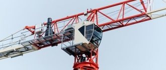
Tower cranes
- these are machines with a boom fixed at the top of a vertical tower, they carry out work on moving cargo and installing building structures through a combination of work movements: lifting, lowering the load, changing the reach, turning the boom and moving the crane itself. These are the main lifting machines in many industries and construction. Load capacity: from 5 to 250 tons. High maneuverability, large service area and under-shooting space are their advantages.
Tower cranes are classified according to their purpose (construction, installation, loader cranes); if possible, movement (on rails; stationary or attached; self-elevating); by the method of changing the hook reach (with a lifting boom and with a horizontal beam); by type of rotating elements of tower-boom equipment (with rotating towers or heads); by type of metal structures (lattice and tubular).
About the indexing system. They are designated by the type index KB-0000. Basic models of tower cranes are designated by the letters KB (tower crane) and numbers (Fig. 6.10).
Rice. 6.10. Tower Crane Indexing System
The first number (I) is the size group for the load moment.
The second two digits (II, III) are the serial number of the base vehicle, which has a rotating or fixed turret.
The fourth (IV) is the version number that differs from the base model, for example, in boom length, lifting height, and load capacity.
After the numbers (V) - the designation of the next modernization (A, B, C) and the climatic version for cold, tropical and tropical humid climates (HL, T, TV) can be indicated.
Tower crane with slewing tower
(Fig. 6.7, a) consists of a fixed frame with a running gear and its drive and a rotating part. The latter includes a rotating platform with a counterweight, a rotation mechanism, cargo and boom winches, a tower, a boom, and pulleys. All mechanisms have electric drive. The boom can be equipped with a load carriage. The supporting part includes a running frame, articulated brackets and four running trolleys.
Fixed tower cranes
(Fig. 6.7, b) the difference is that, together with the lower frame and running bogies, the fixed part also includes a tower with a portal and ballast in the lower part (for stability against capsizing). With a lifting capacity of more than 10 tons, it is more advisable to use these cranes.
Attached (stationary) tower cranes
– for the construction of high-rise structures (150m or more). They consist of a rotating head and a horizontal boom with a load carriage moving along it. They are installed on a special foundation or on part of the foundation of a building. The tower is attached to the building using embedded frames. The tower is built up in sections 2.5-7m long.
Adjustable (self-climbing) cranes
used in the construction of high-rise buildings with a rigid and durable metal frame. The difference is a short tower without a portal and the presence of a clip enclosing the tower. The tower rests on a support beam with folding stops. The lifting capacity of the cranes is up to 15 tons, and the load moment is 3300 kN m.
Self-propelled jib cranes.
This is a large group of cranes with high transport maneuverability, independent power supply and a variety of working equipment. Running equipment – caterpillar and pneumatic wheels. Such cranes use a variety of booms: straight short (main), extended with inserts and with jib.
A self-propelled jib crane consists of a running gear, a slewing ring, a rotating platform with crane equipment, a jib or tower-jib working equipment, a power plant, drive mechanisms and a control system.
Main parameters: weight, load moment, maximum lifting capacity, hook reach, maximum hook lifting height, hook lowering depth, undercarriage track, undercarriage base, specific ground pressure or undercarriage axle load, speeds (lifting, lowering, landing, lifting, horizontal movement of cargo), rotation speed of the turning part, working and transport speeds, power of the power plant, crane performance, etc.
According to GOST 22827-85, self-propelled cranes are assigned the following indices: KA-0000 - for truck-mounted cranes; KP-0000 – pneumatic wheels; KG-0000 – tracked; KSh-0000 – for cranes on automotive chassis; KK-0000 – for cranes on a short-base chassis.
The first zero is replaced with a number from 1 to 9 (size group) (load capacity: 4; 6.3; 10; 16; 25; 40; 63; 100; more than 100t).
The second zero is the type of undercarriage (1 – tracked with a minimal supporting surface; 2 – tracked with an increased supporting surface; 3 – pneumatic; 4 – on a special automobile-type chassis; 5 – truck chassis; 6 – tractor; 7 – trailed; 8 – short-wheelbase; 9 – reserve for other running devices).
The third zero - from 6 to 9 - version of the boom equipment (6 - with a flexible rope suspension; 7 - with a rigid hydraulic suspension; 8, 9 - reserve).
The fourth zero is the serial number of the model. Additionally, the letters indicate the next modernization and special climate version.
Crawler cranes.
Travel speed is 0.5-1 km/h. Load capacity from 16 to 250t. The length of straight arrows is 10-15m. Individual electric drive with a primary power unit - a diesel engine and a three-phase alternating current electric generator with a frequency of 50 Hz, voltage 380 and 220 V. Ground pressure up to 0.1 MPa.
The drives of all mechanisms - cargo, boom-lifting, rotary, chassis, etc. - are built according to standard schemes: electric motor - brake - gearbox - working element. The stability and lifting capacity of cranes depends on the size of the supporting contour - the base and the track (Fig. 6.11).
Pneumatic wheel cranes.
These are cranes of the KS and MKP types (Fig. 6.12 and 6.13) with a lifting capacity of 16, 25, 36 and 100 tons. Running equipment: biaxial and multi-axial (up to five axes). Operating speed is 5 km/h, transport speed is 35 km/h or more. Work on remote hydraulic supports. In cramped conditions, a pneumatic crane on a short chassis is good. The boom is telescopic in three sections. Swivel wheels with multi-ply tires allow increased loads and provide a small turning radius.
Self-propelled jib cranes based on two or three-axle trucks - truck cranes - are widely used in construction. Load capacity 4; 6.3; 10; 16; 25; 32t. Cranes with rigid (fixed) and telescopic (sliding) booms.
Cranes on special automobile-type chassis
– for construction and installation works, installation of technological equipment, loading and unloading operations. Their carrying capacity is 25, 40, 50, 63, 100 and 250 tons (foreign models up to 1000 tons). Special chassis (3 to 8 axles) can handle heavy loads. Telescopic booms of 3-5 sections are expanded by hydraulic cylinders.
Tractor cranes
- in off-road conditions. Based on tracked and pneumatic wheeled tractors. Load capacity does not exceed 10t.
Pipe laying cranes
– for work on oil and gas pipelines. Base - crawler tractors. For stability, a folding counterweight (counterweight) is installed on the opposite side of the boom. Feature: moves with a load on a hook. For laying pre-welded and insulated pipelines, single pipes, shut-off valves in a trench, transportation of pipes and pipe sections (strands), for the installation of pumping and compressor stations. The domestic industry produces pipe-laying cranes with a lifting capacity from 6.3 to 50 tons with a minimum reach of 1.5 m, and a hook lifting height of 4.5-7.5 m.
They are equipped with the following rigging installations: universal rope slings, automatic clamps, elastic grips (towels), trolley suspensions, cross-beams with end gripping of pipes for unloading them from pipelines and stacking them in warehouses and bases.
Span type cranes
– the load is within the support contour. These are gantry, semi-gantry, overhead cranes, beam cranes and cable cranes. They have two supports that move on rails or on pneumatic wheels, and a span (a bridge of lattice or box structure).
Gantry cranes
used in warehouses and assembly sites. Load capacity from 1 to 500t. Spans from 9.3 to 50m. Lifting height 7-30m. There are general purpose and special (installation) ones. Constant load capacity over the entire service area, more stable and less material intensive compared to boom lifts. For installation of cement kilns, boilers, turbogenerators - with a load capacity of 100-125 tons with a span of 20-25 m and a lifting height of 12.5-25 m. During the construction of nuclear power plants, gantry cranes with a lifting capacity of 400 tons are used.
Overhead cranes
differ from gantry ones in that they move along rail tracks laid on the columns of the workshop (warehouse). Single beam and double beam. Load capacity from 5 to 500t, span 10-32m.
As a lifting mechanism for single girder overhead cranes, also called jib cranes
, use electric hoists. Load capacity up to 5t, span 5-17m. The crane is controlled from the floor, or less often from the cabin.
Cranes are used in various sectors of the national economy to move goods along spatial trajectories of arbitrary configuration. They are manufactured in the form of cantilever and span structures. The basic parameters of cranes are determined by the parameters of construction projects and their elements.
Jib cranes
- booms with rotating and non-rotating parts (Fig. 6.7). An arrow with a pulley at its end is attached to them, to the movable holder of which a load-handling device is suspended. The clip can be installed on a movable carriage (trolley) moving along the boom. The load in such cranes is always located outside the crane's support contour. Cantilever cranes include mast-jib and tower cranes, a large group of self-propelled jib cranes (crawler-mounted, rail-wheeled, pneumatic-wheeled, on a vehicle-type chassis, automobile, tractor-mounted, pipe-laying cranes, powerful assembly cranes).
Span (bridge) type cranes
consist of a span and a trolley with a pulley moving along it. The load is within the crane's support contour. This group includes overhead and gantry cranes (Fig. 6.8 and 6.9).
Basic parameters of cranes: lifting capacity, lifting height of cargo, cargo outreach, span (distance between the longitudinal axes of the crane track rails), depth of lowering of cargo, track (distance between wheels or tracks), base, speed of lifting cargo, speed of smooth landing of cargo, average speed changes in reach, rotation speed of the rotating part of the crane, speed of movement of the crane.
The dependence of the load capacity on the load outreach is called the load characteristic. Presented graphically. There are min
and
max
reach, corresponding to the highest and lowest load capacity. A change in reach leads to a change in the maximum lifting height of the load. This is a high-altitude characteristic. Combining them on one graph, a cargo-altitude characteristic is obtained. The load capacity multiplied by the reach is the load moment. The contour covering the supporting elements (wheels, outriggers, tracks) is called the support contour.
Average hourly operating performance of cranes (total mass moved per unit time):
(6.13)
where is the maximum load capacity, t;
— crane utilization rates in terms of lifting capacity and time;
— duration of the crane operating cycle, s;
— when reloading bulk cargo with grabs;
- the same, with other devices;
- the same, piece cargo;
— during construction and installation works;
— when calculating the average daily productivity and using the crane 12…14 hours a day;
- when calculating the average annual productivity and crane operation 3600...3800 hours per year.
Mast jib cranes.
These are cranes with a permanently installed mast supported by guy cables (cable-stayed cranes) or rigid braces (strutted or rigid-legged cranes).
They are used for installation of prefabricated structures and technological equipment on large construction sites. Rice.
6.7. Tower cranes: with rotating tower and luffing jib (a); with a fixed tower and a beam boom (b); 1-hook suspension; 2-arrow; 3-head; 4-cabin; 5-spacer; 6-tower; 7-ropes; 8-counterweight; 9,10,19-winches; 11-rotation mechanism; 12-platform; 13-slewing device; 14-ballast; 15-way frame; 16-way trolley; 17-load trolley; 18-counterweight console Fig. 6.8. Overhead crane: 1-bridge; 2-cargo trolley; 3-rail cargo trolley track; 4-fences; 5-stairs; 6-cabin-cradle; 7.8-hook suspensions; 9-cabin; 10-above-ground crane runway
Rice.
6.9. Gantry crane made from shaped rolling posts and beams Cable-stayed mast-jib crane
consists of a mast, a boom, cargo and boom pulleys, electric winches, a support beam holding the mast with cables. At the bottom, through the thrust bearing, the mast rests on a turntable with a rope drive. From above, through the support, it is secured with four, six or eight guys - cables (depending on the load capacity). They are inclined to the horizon at an angle of 300. The cables are pulled and held by hand winches or turnbuckles (turnbuckles) attached to the anchors. The boom is hinged at the bottom and attached to the mast. It is held at the top by a lifting pulley. Their carrying capacity is from 5 to 25 tons.
Rigid mast jib crane.
Its mast is supported by rigid struts resting on beams. To ensure stability of the crane, the beds are loaded with ballast or anchored. Here the boom can be extended (1.5 - 2 times compared to the previous crane). Their carrying capacity is from 0.75 to 35 tons.
Tower cranes
- these are machines with a boom fixed at the top of a vertical tower, they carry out work on moving cargo and installing building structures through a combination of work movements: lifting, lowering the load, changing the reach, turning the boom and moving the crane itself. These are the main lifting machines in many industries and construction. Load capacity: from 5 to 250 tons. High maneuverability, large service area and under-shooting space are their advantages.
Tower cranes are classified according to their purpose (construction, installation, loader cranes); if possible, movement (on rails; stationary or attached; self-elevating); by the method of changing the hook reach (with a lifting boom and with a horizontal beam); by type of rotating elements of tower-boom equipment (with rotating towers or heads); by type of metal structures (lattice and tubular).
About the indexing system. They are designated by the type index KB-0000. Basic models of tower cranes are designated by the letters KB (tower crane) and numbers (Fig. 6.10).
Rice. 6.10. Tower Crane Indexing System
The first number (I) is the size group for the load moment.
The second two digits (II, III) are the serial number of the base vehicle, which has a rotating or fixed turret.
The fourth (IV) is the version number that differs from the base model, for example, in boom length, lifting height, and load capacity.
After the numbers (V) - the designation of the next modernization (A, B, C) and the climatic version for cold, tropical and tropical humid climates (HL, T, TV) can be indicated.
Tower crane with slewing tower
(Fig. 6.7, a) consists of a fixed frame with a running gear and its drive and a rotating part. The latter includes a rotating platform with a counterweight, a rotation mechanism, cargo and boom winches, a tower, a boom, and pulleys. All mechanisms have electric drive. The boom can be equipped with a load carriage. The supporting part includes a running frame, articulated brackets and four running trolleys.
Fixed tower cranes
(Fig. 6.7, b) the difference is that, together with the lower frame and running bogies, the fixed part also includes a tower with a portal and ballast in the lower part (for stability against capsizing). With a lifting capacity of more than 10 tons, it is more advisable to use these cranes.
Attached (stationary) tower cranes
– for the construction of high-rise structures (150m or more). They consist of a rotating head and a horizontal boom with a load carriage moving along it. They are installed on a special foundation or on part of the foundation of a building. The tower is attached to the building using embedded frames. The tower is built up in sections 2.5-7m long.
Adjustable (self-climbing) cranes
used in the construction of high-rise buildings with a rigid and durable metal frame. The difference is a short tower without a portal and the presence of a clip enclosing the tower. The tower rests on a support beam with folding stops. The lifting capacity of the cranes is up to 15 tons, and the load moment is 3300 kN m.
Self-propelled jib cranes.
This is a large group of cranes with high transport maneuverability, independent power supply and a variety of working equipment. Running equipment – caterpillar and pneumatic wheels. Such cranes use a variety of booms: straight short (main), extended with inserts and with jib.
A self-propelled jib crane consists of a running gear, a slewing ring, a rotating platform with crane equipment, a jib or tower-jib working equipment, a power plant, drive mechanisms and a control system.
Main parameters: weight, load moment, maximum lifting capacity, hook reach, maximum hook lifting height, hook lowering depth, undercarriage track, undercarriage base, specific ground pressure or undercarriage axle load, speeds (lifting, lowering, landing, lifting, horizontal movement of cargo), rotation speed of the turning part, working and transport speeds, power of the power plant, crane performance, etc.
According to GOST 22827-85, self-propelled cranes are assigned the following indices: KA-0000 - for truck-mounted cranes; KP-0000 – pneumatic wheels; KG-0000 – tracked; KSh-0000 – for cranes on automotive chassis; KK-0000 – for cranes on a short-base chassis.
The first zero is replaced with a number from 1 to 9 (size group) (load capacity: 4; 6.3; 10; 16; 25; 40; 63; 100; more than 100t).
The second zero is the type of undercarriage (1 – tracked with a minimal supporting surface; 2 – tracked with an increased supporting surface; 3 – pneumatic; 4 – on a special automobile-type chassis; 5 – truck chassis; 6 – tractor; 7 – trailed; 8 – short-wheelbase; 9 – reserve for other running devices).
The third zero - from 6 to 9 - version of the boom equipment (6 - with a flexible rope suspension; 7 - with a rigid hydraulic suspension; 8, 9 - reserve).
The fourth zero is the serial number of the model. Additionally, the letters indicate the next modernization and special climate version.
Crawler cranes.
Travel speed is 0.5-1 km/h. Load capacity from 16 to 250t. The length of straight arrows is 10-15m. Individual electric drive with a primary power unit - a diesel engine and a three-phase alternating current electric generator with a frequency of 50 Hz, voltage 380 and 220 V. Ground pressure up to 0.1 MPa.
The drives of all mechanisms - cargo, boom-lifting, rotary, chassis, etc. - are built according to standard schemes: electric motor - brake - gearbox - working element. The stability and lifting capacity of cranes depends on the size of the supporting contour - the base and the track (Fig. 6.11).
Pneumatic wheel cranes.
These are cranes of the KS and MKP types (Fig. 6.12 and 6.13) with a lifting capacity of 16, 25, 36 and 100 tons. Running equipment: biaxial and multi-axial (up to five axes). Operating speed is 5 km/h, transport speed is 35 km/h or more. Work on remote hydraulic supports. In cramped conditions, a pneumatic crane on a short chassis is good. The boom is telescopic in three sections. Swivel wheels with multi-ply tires allow increased loads and provide a small turning radius.
Self-propelled jib cranes based on two or three-axle trucks - truck cranes - are widely used in construction. Load capacity 4; 6.3; 10; 16; 25; 32t. Cranes with rigid (fixed) and telescopic (sliding) booms.
Cranes on special automobile-type chassis
– for construction and installation works, installation of technological equipment, loading and unloading operations. Their carrying capacity is 25, 40, 50, 63, 100 and 250 tons (foreign models up to 1000 tons). Special chassis (3 to 8 axles) can handle heavy loads. Telescopic booms of 3-5 sections are expanded by hydraulic cylinders.
Tractor cranes
- in off-road conditions. Based on tracked and pneumatic wheeled tractors. Load capacity does not exceed 10t.
Pipe laying cranes
– for work on oil and gas pipelines. Base - crawler tractors. For stability, a folding counterweight (counterweight) is installed on the opposite side of the boom. Feature: moves with a load on a hook. For laying pre-welded and insulated pipelines, single pipes, shut-off valves in a trench, transportation of pipes and pipe sections (strands), for the installation of pumping and compressor stations. The domestic industry produces pipe-laying cranes with a lifting capacity from 6.3 to 50 tons with a minimum reach of 1.5 m, and a hook lifting height of 4.5-7.5 m.
They are equipped with the following rigging installations: universal rope slings, automatic clamps, elastic grips (towels), trolley suspensions, cross-beams with end gripping of pipes for unloading them from pipelines and stacking them in warehouses and bases.
Span type cranes
– the load is within the support contour. These are gantry, semi-gantry, overhead cranes, beam cranes and cable cranes. They have two supports that move on rails or on pneumatic wheels, and a span (a bridge of lattice or box structure).
Gantry cranes
used in warehouses and assembly sites. Load capacity from 1 to 500t. Spans from 9.3 to 50m. Lifting height 7-30m. There are general purpose and special (installation) ones. Constant load capacity over the entire service area, more stable and less material intensive compared to boom lifts. For installation of cement kilns, boilers, turbogenerators - with a load capacity of 100-125 tons with a span of 20-25 m and a lifting height of 12.5-25 m. During the construction of nuclear power plants, gantry cranes with a lifting capacity of 400 tons are used.
Overhead cranes
differ from gantry ones in that they move along rail tracks laid on the columns of the workshop (warehouse). Single beam and double beam. Load capacity from 5 to 500t, span 10-32m.
As a lifting mechanism for single girder overhead cranes, also called jib cranes
, use electric hoists. Load capacity up to 5t, span 5-17m. The crane is controlled from the floor, or less often from the cabin.
Design features of overhead double girder cranes
Modern double-girder electric overhead cranes consist of the following structural elements:
Cargo trolley
Span beams
End beams
Control cabin
The double-girder design provides the crane with maximum stability and reliability, since the entire mechanism rests on the stationary columns of the building.
Electric overhead double-girder cranes are used year-round, both in industrial premises and on open construction and production sites. To rationally use the power of the equipment, crane models are created that are equipped with two trolleys with different lifting capacities. The service life of a crane with two lifting devices of different loads is usually significantly higher than equipment with one type of device.