Did you like the article? Follow our channel for new ideas of useful car tips. Subscribe to us in Yandex.Zen. Subscribe.
The most popular ZIL 130 truck lasted on the plant’s assembly line for more than 30 years. The unpretentious engine, reliable chassis and connection diagram of the ZIL 130, proven on its predecessors, allowed it to gain recognition in the cargo transportation market and firmly gain a foothold in the status of a popular “vehicle”.
Generator circuit for ZIL "Bychok"
The 90 ampere Bychkovsky generator 2022.3771 can be installed on Valdai, Gazelle, various UAZ vehicles, you just need to select a pulley and not pay attention to the alternating voltage terminal block.
Use an external voltage regulator - Gazelevsky 131.3702 Zil "Bychok" still exists and sometimes comes to repair the generator or starter.
The body of the generator is the same as on Gazelles and old Zils, but the pulley is different, doubled for narrow belts.
Accordingly, in its place you can install any generator from the many produced in such a housing.
In principle, you can install any generator, you just need to connect it correctly.
The generator must power 12 Volt electrical equipment and charge two series batteries, which together provide 24 Volts.
They would immediately make everything 24 Volt and install everything Kamaz.
But they didn’t do that, and you will have to use 12 Volt electrical equipment.
The starter, however, is 24-volt. Such a starter for a heavy engine is lighter and the long wires that go to it (and these are the thickest wires that are in the car) can be made thinner. The current is less, which means that all contacts in the starter circuits will work longer and more reliably.
To get 24 Volts you need 2 batteries and they need to be charged with a voltage of 28 Volts.
The generator uses 14 Volt, and to obtain a voltage of 28 Volt, it is raised using a transformer converter.
The generator, when the VSiP lock is turned on, receives voltage to point D. The initial excitation current passes through the control light on the instrument panel.
It goes to the plus of the voltage regulator, immediately to point Ш of the regulator, and then, through the brushes, to the excitation winding. It goes back into the voltage regulator and goes to the collector of transistor T6, the transistor is open, and the current goes to ground.
This small current, limited by the light bulb, excites the generator, and a voltage appears at its output.
Voltage also appears at the output of the additional diodes, and the current into the excitation winding now comes from the additional diodes.
This is the purpose of the additional diodes - to power the excitation winding.
The generator is fully excited and enters operating mode.
The voltage that acts from additional diodes on the plus of the regulator is transmitted to the input divider R1 R2 (R3). From the midpoint of the divider, part of this voltage is applied to the zener diode CT. While the zener diode is closed, the voltage at the generator output can increase. As soon as it reaches a value of 14.2 Volts, the zener diode will break through, all transistors will work and transistor T6 will close, the excitation current will stop and the voltage will begin to drop. The voltage on the divider R1 R2 will decrease, the zener diode will close, the circuit will work in the reverse order and transistor T6 will open, again, an excitation current will appear, the voltage will begin to rise and then everything will repeat, so that the regulator will not allow the voltage to rise above 14.2 V and fall below 13.6 V. That is, the voltage will be maintained at the specified level.
Several stages in the circuit, as well as feedback circuits, provide the necessary response speed and precise voltage regulation.
The input divider, which senses the generator voltage and supplies it to the zener diode, has a third resistance, this is R3, it can be located in the battery terminal. R3 is a thermistor that changes its resistance depending on the temperature of the electrolyte. If the temperature rises, the thermistor changes the voltage at the midpoint of the divider so that the regulator reduces the operating voltage of the battery; if the battery cools, the generator voltage increases accordingly. This voltage regulation significantly extends the life of expensive batteries.
Modification Policy
With such serious support and recognition, the car plant has been receiving orders for modifications of the ZIL 130 since 1967. Two areas should be highlighted in particular:
- Production of models capable of serving in the Arctic (at temperatures below -45C). These machines were produced for the development of fields in Siberia and the Far East;
- Production of models designed to work in the tropics (at 100% humidity). They were produced for foreign countries, which were helped by the Soviet government.
For reference: for the Arctic, cars were made from materials capable of ensuring vehicle operation in subzero temperatures. As for the tropics, the ZIL 130 wiring and a number of electrical components were sealed.
Modification ZIL 130S
In the 1970s, many mineral deposits were discovered in Siberia. The price of production was low, and their development required trucks capable of operating in difficult climatic conditions.
You can judge the difficulties that cars face in the far north from the video presented in our article. This black and white copy, recreated from archival materials from the Likhachev plant, clearly demonstrates the capabilities of the ZIL 130 S.
Watch the thematic video at the end of the article.
Among the configuration of the ZIL 130S (Siberia), the following electrical equipment characteristics are noted:
- Pre-heater with autonomous power source;
- Cabin with double glazing and additional independent heating with high-power electric fan;
- Fog light and adjustable light on command from the cab;
- Two independent gas tanks with a fuel level indicator on the dashboard;
- Battery electrolyte temperature sensor.
For reference: the battery itself was placed in a special thermal box and heated during operation by engine exhaust gases. The electrical wiring on the ZIL 130 is made of special rubber-plastic that can withstand low temperatures.
Special versions
Additionally, load changes vary depending on clients:
- For the Ministry of Defense (MoD);
- For emergency services (mainly firefighters);
- For civilian enterprises.
In particular, for the needs of the army, the automobile plant has mastered the production of the ZIL-130E car, for which:
- Shielded electrical wiring ZIL 130 was installed;
- generator G-51 (power 450 W, 40A);
- voltage regulator relay PP-51;
- ignition distribution switch R-102;
- high-voltage ignition coil B-102B;
- electric starter ST-2;
- spark plugs CH-307.
For reference: ZIL 130 is especially known as a fire engine. Many of the “pozhoks” produced in the 1980s still serve in Russian cities.
Converter 12V-24V
The converter that allows you to get 24 Volts to charge the second battery is a transformer and a diode bridge, the same as in the generator only without additional ones. diodes.
The transformer does not increase the voltage, its transformation ratio is 1 - as much as is supplied, so much is removed, but what is important here is that the transformer transmits energy through a magnetic field and decouples electrical circuits. The voltage obtained from the converter can be applied sequentially to the voltage from the output of the generator and they add up, so the output is 24 Volts, or rather double the output voltage of the generator.
Converter
The transformer is an alternating current device, so it is necessary to supply voltage to it not from the generator output, where it is already constant, but from the inside, from the generator windings to the diode bridge; for this, an additional block is made, the three terminals of which are connected to the winding phase terminals.
Possible wiring problems
The downside to the truck's proximity system in the old days was the lack of electronic parts and their reliability to handle harsh weather conditions.
Wiring problems may occur due to:
- circuit break;
- damage to current-carrying elements: cores, contacts, wires;
- poor contact at connection points;
- oxidation of terminals and contacts;
- insulation damage;
- lack of food.
An open circuit can be determined using a voltmeter or test light.
Broken wires must be replaced with intact ones. If it is not possible to make a replacement, you can temporarily connect the broken ends of the wire by wrapping them with insulating tape.
You should ensure that the contacts are clean, otherwise the current will not be able to break through the film formed from oil or oxide.
What kind of converter is it, why is it included in the generator circuit?
In order to make the starter lighter, it is designed for a voltage of 24 V. In this case, with the same power, it consumes less current, which means the long wires that go to it from the battery can be made thinner. Everything becomes more reliable, contacts, brushes, retractors.
24 Volts are obtained by connecting two batteries in series. In order to charge the second battery, you need to apply a voltage exceeding 24 V to them. This voltage is obtained by doubling the generator voltage. The converter receives alternating voltage from the generator and produces its voltage of 14 V. It can be added to the generator voltage and the result is 28 V.
Turning wheels ZIL 130: conditions and principle of operation
The direction of movement of the car is changed by turning the steered wheels. In this case, the axes rotate around special axles so that in the plane they touch in one place, which is called the center. It determines the turning radius and curvature of the vehicle.
Off-road vehicles may have a different number of pairs of steered wheels, but increasing their number makes it difficult to control, especially when the rear wheels are also steerable.
To begin with, the vehicle enters a zigzag, where it travels in an uneven direction. Then the wheels no longer rotate around the axle, and the machine rotates uniformly with an arc of a circle with a given radius R and constant angular velocity.
Determining the center of rotation of a car is similar to determining the center of a solid flat body. If a flat rigid body returns, then its center of rotation is determined by the velocities of any two of its points (a, b), drawing perpendiculars to the velocity vectors (a and b) of these points, and at their intersection we graphically determine the center of rotation of the body. The radius and angular velocity are determined simultaneously. In a car, the “rigid body” is the frame (body), and points a and b belong to the frame, therefore the theorem about the rotation of a rigid body fully applies to the car.
However, for pure rocking of the wheels when turning a car, when they roll without deviation to the side, it is necessary that the steered wheels return to different, but very specific angles. This can be done if, when moving, the axes of rotation of all the wheels of the car intersect at one point - the center of rotation. To fulfill the last condition, it is necessary that the extensions of the sides of the steering linkage intersect on the longitudinal axis of the car at a distance of 3/4 L from the front axle.
If the car is two-axle with one pair of steered wheels, then the condition for pure swing of the wheels during a turn will be the location of the center of rotation on the axis of the unsteered wheels. In a three-axle car, the center is at the intersection of the front wheel axles and the bogie axle, because the intersection with the rear wheel axles would give two centers of rotation. To reduce the slippage of the wheels of the rear axles when they are displaced, their axes are brought as close as possible to the axis of the bogie.
Is it possible to install a simple generator from Gazelle on the Bychok?
If you install a 12 Volt starter, and this option is quite possible, since for the D 242 engine all offered types of starters have both 12 Volt and 24 Volt versions. The 28 Volt voltage is no longer needed, there is no need for a converter, there is no need for alternating voltage outputs from the generator, which means any generator in such a housing will do.
A powerful starter will still require two batteries, but in this case they need to be connected in parallel.
The converter is no longer needed and no AC outputs are needed. The light on the instrument panel needs to be bypassed; charging can be monitored using a voltmeter.
Source
Sequencing
Get ready for work. To connect the ZIL-130 car generator via relay regulator 13. 3702-01, you will need:
- Five single-pin connectors (female). Preferably isolated.
- Three pieces of elastic wire. It is desirable that they differ in the color of the insulation.
- A roll of electrical tape.
- Crimping pliers for wire lugs or, alternatively, pliers.
If all this is available, we connect the generator of the ZIL-130 car, proceeding in the following sequence:
- We measure out pieces of wires of the required length, leaving a margin of 10 - 15 centimeters. The wiring should not be stretched.
- We connect two wires to the connector installed on the positive terminal of the brush assembly, one of which, using the “mother”, is connected to the relay-regulator, and the other to the positive terminal of the ignition switch.
- We use the last piece of wire, having secured the connectors on it, to connect the second contact of the brush holder to the “Ш” (top) terminal on the relay regulator.
If you do not have the necessary experience, it is advisable to practice by first removing parts from the car. But the final connection of the ZIL-130 generator to the on-board network must be made by installing the components in their standard places. It is recommended to protect the wires from mechanical damage:
- Using corrugated tubes of suitable diameter, made of heat-resistant plastic, as cable ducts.
- Secure them to the body and generator mounting brackets using special clamps or cable ties.
It won't require much effort on your part.
For clarity, the connection diagram of the ZIL-130 generator to the relay regulator 13. 3702-01 is shown in Figure No. 1.
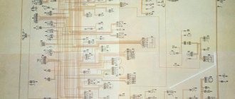
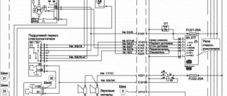
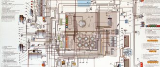
ZIL-5301. Electrical diagram
1 — front direction indicators left 4619.3726 and right 4609.3726;
5 - electric sound signal 20.3721-01 or S3-3B;
9 — coolant overheat indicator sensor TM111;
19 — coolant level indicator sensor DKU1.M;
23 — electronic unit of fan speed controller ROV2.MS;
27 — electric motor of the windshield wiper 35.5205;
32 – voltage regulator 42.3702 or 206-3702 or 207.3702;
39 and 86 - side middle marker lights 43.3731;
46 - push-button thermobimetallic fuse for 20 A129.3722;
57, 110 and 113 - connecting panels;
61 — relay for turning on the spark plug of the electric torch device 111.3747 or 90.3747, or 851.3747;
65 — thermal relay of the electric torch device 12.3741;
69 — generator set status indicator;
74 — oil pressure drop indicator 2202.3803-23;
79 — indicator of reserve fuel level 2202.3803-19;
85 — remote battery switch 11.3704;
90 — control unit for electric corrector BUK021;
94 — wiper switch 9912.3709;
98 — rear fog lamp switch 3832.3710-02.04;
107 and 120 — side rear marker lights 43.3731;
112 — license plate lights FP134;
2 — headlights 6002/6012.3711 or 68/681.3711;
6 and 14 — side front marker lights 43.3731;
10 — coolant temperature sensor TM100-V or 2442.38.28 or TM100V-01 or TM100V-K;
16 — oil pressure indicator sensor 18.3829 or MM355;
20 — electric motor 11.5208 windshield washer;
24 — electric motor of the ME272-B cabin heater;
28 — starter starting contactor 59.3747;
33 - starter 20.3708 or ST142N;
40 — breaker RS950С direction indicators;
48 - push-button thermobimetallic fuse 30 A 291.3722;
58 — starter automatic shutdown relay 111.3747-10 or 90.3747-22 or 853.3747;
62 — relay for fog lights and rear fog light 111.3747, or 90.3747, or 851.3747;
66 — RS492 parking brake warning switch;
70 — instrument cluster 36.3801;
75 — signaling device for switching on the electric torch device 2202.3803-17;
80 – brake system fault buzzer 733.3747-01;
91 — electronic control unit for windshield wiper and washer 92.3761 (installed on the bus);
95 — switch 20.3704 for instruments and starter;
99 — switch for heating elements of rear-view mirrors 3802.3710-02.23;
108 and 118 — rear marker lights 35.3731;
3 — electric drive for headlight range control EPKO22;
7 and 15 — side direction indicator lights 5702.3726;
11 - fuel shut-off electromagnet;
17- air filter clogging indicator sensor 13.3839;
21 and 34 — engine compartment lamps PD308-A;
25 — front contour lights 36.3731;
29 — brake signal switches for front and rear brakes 2802.3829 or 3402.3829;
35,37,53,54,55,56,71,77, 102 and 119 - connecting terminals;
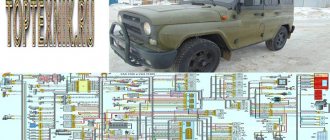
Zyl dump truck
The relay regulator can be checked directly on the bus. Detailed testing of various relays is described in the relevant sections of the book. A break in the circuit of sources and consumers of electrical energy occurs due to melting of a fuse, opening of contacts in a thermobimetallic fuse, rupture of wires, loose fastening of wire tips on the terminals, broken contact in the plug connection of wires, broken contact in switches and switches, broken circuit in consumers, burnt out thread incandescence in a lamp, burnout of an additional resistor or electric motor winding, etc.
If there is a break in the circuit, you need to disassemble the block and solder the broken section of the board, you can solder a conductor parallel to it or replace the printed circuit boards. To identify the location of the break, a wire with a spring tip is connected to ground, and the tip of the tip begins to touch the circuit clamps in the direction from the non-working device to the battery.
Then three modifications came out: with a carburetor engine; with a diesel engine; with unshielded wiring for civilian needs.
To transmit electrical energy from a source to consumers, wires are used, which are divided into low and high voltage wires based on insulation.
If there is a break in the circuit, you need to disassemble the block and solder the broken section of the board, you can solder a conductor parallel to it or replace the printed circuit boards.
To control the rectifier, connect a voltmeter or test lamp to its positive and negative terminals and disconnect the wire from terminal B of the relay regulator. Turn on the fuse and close the contacts by pressing a button. VEHICLE ELECTRICAL EQUIPMENT.
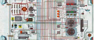
Electrical wiring ZIL 5301: color diagram with description
Nothing brings a large family together like a small car.
As history shows, unified all-Union planning of the national economy also had its shortcomings. In particular, when the country needed a light-duty truck, domestic automakers did not have promising developments, and therefore ZIL was forced to borrow ideas from Mercedes.
Restyled ZIL 5301 – photo from the exhibition “Autotrans 2012”
Excursion into history
- We are, of course, talking about the “Bull” - a popular model of our days, built on the Mercedes T2 platform , and capable of solving any transport problems on short and medium routes.
- The reason for its appearance was the transition to a market economy in the Russian economy, as a result of which the demand for gasoline heavy-duty vehicles fell catastrophically.
- And thanks to the new model, the plant managed to survive and even increase production volumes, benefiting from government support.
For reference: Industry index - received 5301 cars by mistake. According to GOST from 1966, “Bychok” had to have an index of 3301, corresponding to the small-tonnage class. However, when drawing up the certificate, an unfortunate mistake was made, which, when discovered, was too late to correct anything, because All documentation for the car already indicated the index 5301.
Possible problems and solutions
Many people consider the Internet to be an inexhaustible source of reliable information. However, it is not. For those who want to know how the generator of a ZIL-130 car is connected, search engines provide old-style electrical diagrams with DC devices. Confusion ensues. We will try to save car owners from unnecessary problems.
Since the advent of devices generating alternating current, the circuit diagram for connecting the ZIL-130 generator has not undergone any changes. But the problem is that old-style electrical equipment parts are rarely found on sale. Therefore, it is advisable to replace them with available components.
Some experts suggest using for these purposes relay regulators that have proven themselves in operation under the marking 121 3702, installed on VAZ cars. However, this option has its drawbacks, the main one of which is the need to make changes to the electrical circuit of a popular truck model.
This can be avoided by connecting the ZIL-130 generator, equipped with a two-contact brush assembly, through a similar device that is equipped with some GAZ models. It is marked 13. 3702-01. In this case, the cost of conversion is minimal, since the part is inexpensive, and the electrical circuit remains unchanged. By performing a number of simple steps, you will increase the reliability and maintainability of your equipment.
Model features
Main modifications of ZIL 5301 according to factory documentation
According to the manufacturer, the car’s design served as a platform for 35 modifications for various purposes. The photo above shows the factory instructions.
It should be noted that most modifications were ordered:
- state companies;
- public utilities;
which allowed the plant to load production capacity. The presented video shows only some of the modifications of this model found on domestic roads.
At the same time, to reduce the cost of the car, the manufacturer used components and assemblies from other models, for example, the electrical wiring of the ZIL 4331, since the high price of a car with original parts developed from scratch would not allow it to compete in market conditions.
In particular, the following were installed on the Bychok:
- The cabin is from model 4331. Along with it, the ZIL 4331 wiring and power steering migrated;
- Gearbox ZIL 130.
All features of the electrical circuit are described in the instruction manual
Summary
Despite the difficult market times, the automaker was able to offer a new truck that allowed it to withstand difficult economic conditions. And although domestic cars are not of high build quality, a variety of modifications of the ZIL 5301 are still in service in many cities and villages.
We hope that your car will serve for a long time, and the materials and photographs proposed in the article will help in its independent maintenance. Good luck on the roads!
Similar materials
Names such as the Paris-Dakar Rally and Mitsubishi Pajero are inextricably linked. Of course, after all, behind the wheel of this Japanese SUV, different racers won 12 victories.
Many car owners are thinking about how they can tune Dodge Caravan headlights, because now lensed designs of excellent quality are widespread.
The absence of fog lights on a modern car significantly worsens its safety in conditions of poor visibility. On Kalina cars the manufacturer already.
Model 3110 of the Gorky Automobile Plant was launched into production in 1997 and was conceived as a more modern and improved solution, comparable to the configuration.