It is necessary to ensure that there are no leaks of coolant and fuel in the connections of pipelines, hoses and taps, systematically inspect the pre-heater and immediately correct any detected faults. The connections between the fuel lines and the heater must be sealed, since air leaks into the fuel system are not allowed. The presence of air or a leak in the fuel system of the heater leads to unreliable operation and random stoppage of the heater.
It is necessary to regularly inspect the fastenings of the boiler and pump unit, clean all equipment from dirt, wash the filters of the solenoid valve and nozzles, clean the drain holes of the fuel pump and the drain pipe of the boiler burner from dirt. In addition, it is also necessary to clean the spark plug electrodes from carbon deposits, disassemble and wash the injector in gasoline or acetone, wash the solenoid valve channels in kerosene or gasoline, clean the valve core from dirt, check the condition of the wires and the fastening of the heater control devices.
Possible malfunctions of the preheater and ways to eliminate them
| Cause of malfunction | Remedy |
When starting the heater, the electric motor of the pump unit does not rotate, and the fuse trips.
| Freezing of the fan impeller due to incomplete removal of water after washing the car or fording | Using available means (a torch, a blowtorch), heat the fan housing and the liquid pump. In this case, it is necessary to ensure that the flame does not fall on the hoses and wires. |
There is no spark at the spark plug electrodes.
| There is no voltage at the terminals of the wires supplying low voltage current to the induction coil | Determine the location of the electrical circuit damage and eliminate the fault |
| The induction coil does not work | Disconnect the high voltage wire from the spark plug and secure its end at a distance of 3-5 mm from the ground of the car. If there is no spark when the switch is moved to position I, the induction coil should be replaced |
| The spark plug doesn't work | Replace spark plug |
The electric heater does not work.
| There is no voltage at the heater power terminal | There is no contact in the electric heater power circuit; The relay in the electric heater circuit has burned out. Tighten up contacts; Replace the relay if necessary |
| Heating element does not work | Replace |
There is no or insufficient fuel supply to the injector.
| The electric motor of the pump unit does not work | Check the motor circuit; Check the tightness of the tip on the terminals |
| The solenoid valve does not operate (there is no click when the switch is moved to position II) | Check the serviceability of the circuit supplying current to the valve and the tightness of the terminals |
| The fuel filter in the solenoid valve or in the injector is clogged | Remove the filter, rinse and blow with compressed air; replace the filter if necessary |
| Nozzle clogged | Remove the nozzle and disassemble it. Wash parts in gasoline or acetone. Assemble the nozzle and check the fuel atomization without screwing the nozzle into the burner |
| Presence of air in the fuel line | Bleed the fuel system by loosening the connection of the tube to the electric fuel heater. When fuel appears, secure the tube. Eliminate air leaks by checking the pipe connections |
| Insufficient fuel pressure supplied by the pump | Adjust fuel consumption using the fuel pump pressure reducing valve |
The heater smokes or there is an open flame during operation.
| Fuel pump performance is incorrectly adjusted | Reduce fuel consumption by adjusting the pressure reducing valve on the fuel pump |
| Low motor shaft speed | Recharge the battery; check the serviceability of the electric motor |
| Heating has formed in the combustion chamber and the heater boiler | Disassemble the assembly, remove carbon deposits and blow with compressed air |
Continuous warming up of the engine by the heater.
| Low fuel consumption due to clogged filters, injectors, leaking fuel lines, improper adjustment of the fuel pump | Wash the filters, injectors, eliminate leaks in the fuel lines, adjust the pressure reducing valve of the fuel pump |
| Low motor shaft speed | Recharge the battery; check the serviceability of the electric motor |
To remove carbon deposits, it is necessary to blow out the boiler, combustion chamber and flue with compressed air, disconnecting the air supply hose.
It is necessary to ensure that the heater fuel pump is adjusted correctly. The optimal supply of fuel to the combustion chamber in operation is determined by the uniform hum of the flame, stable operation of the heater and the absence of an open flame from the combustion chamber flue.
Fuel consumption is controlled by the pressure reducing valve of the fuel pump. To increase the amount of fuel entering the combustion chamber through the nozzle, unscrew the cap nut on the fuel pump, the lock nut of the adjusting screw and turn the screw to the right until the heater reaches a stable operating mode.
After completing the adjustment, lock the adjusting screw with the lock nut and screw on the cap nut:
Operating the heater with an open flame at the outlet is unacceptable.
After washing the car or fording in the cold season, remove water that has entered the air tract of the fan by turning on the pump unit for 3-4 minutes (put the switch to position III, having first disconnected the wire of the electric fuel heater).
What is PZD
A pre-heater on KamAZ is necessary to warm up a cold engine equipped with a liquid cooling system. It also prevents glass from icing up.
Device
The device includes the following elements:
- heat exchanger;
- burner;
- air blower;
- glow plug;
- flame sensor;
- thermal safety mechanism;
- temperature indicator;
- inlet and outlet pipe;
- flame swirler and solenoid fuel valve;
- exhaust pipe;
- high pressure fuel pump and harness;
- stabilizer and fan;
- pump unit and fuel tank valve.
Technical characteristics of the engine pre-start fuse:
| Heating capacity, kW | 12+1 |
| Fuel fluid consumption, l | During operation - 1.6 At idle - 0.7 |
| Diesel fuel requirements | GOST 305-82 (50% diesel + 50% gasoline) |
| Voltage, V | Up to 30 |
| Electrical power consumption, W | 70+10 |
| Rated voltage, V | 24 |
| Minimum amount of liquid for heating, l | 10 |
| CO content of gases at the outlet | No more than 4 |
| Smokiness | No more than 0.2% |
| Maximum operating pressure, kPa | From 40 |
| Weight, kg | 9 |
| Resource, h | 3000 |
Principle of operation
The PZD is connected to the liquid system of the heating and cooling device of the vehicle. The system must be filled with coolant.
The heating device itself does not depend on whether the engine is running or not.
The heating device is powered by the vehicle. When the diesel engine is turned on, fuel begins to flow from the plunger-type electromagnetic fuel pump through the glow plug bushing. The fuel liquid is combined with air, which is supplied by a special supercharger. The air flow passes through the pipe. The resulting mixture begins to ignite from the hot spiral of the glow plug, after which the glow plug turns off.
Cold engine starting assistance system (EFI and preheater)
System for facilitating cold engine starting (ECU and pre-heater)
In the cold season, the engine is started using an electric torch device or a pre-heater . The maximum temperatures for reliable starting of a cold engine and the time it takes to prepare the engine to accept a load at this temperature are given in the table.
An electric torch device (EFD) is used to facilitate engine starting at ambient temperatures from minus 5 to minus 20 °C.
| Options | Without the use of EFU | Using EFU | With preheater |
| Limit temperature for reliable start-up, °C, not higher | minus 10 | minus 22 | minus 45 |
| Engine preparation time to accept load, min, no more | 8 | 10 | 36 |
| Viscosity (grade) of engine oil, mm/s, (cSt) | 4000 | 6000 | winter, class 8 GOST 17479.1-85 |
| Fuel according to GOST 305-82 | diesel "Z" minus 35 | diesel "Z" minus 45 | diesel "A" |
Checking the functionality of the EFU
- Check the serviceability of the ECU warning lamp on the instrument panel in the cab (see Fig. Instrument panel) by pressing the control button.
- Determine the time from the moment the EPI is turned on until the control light comes on. lamps. To turn on the EFU for the first time, it should be: - at a positive air temperature - 50..70 s; - at negative air temperature - 70-110 C. When the EPI is turned on again, the time it takes for the control lamp to light up is reduced.
- Check for the presence of a flame in the intake pipes by touch, by heating the manifolds next to the spark plugs. If one of the spark plugs fails, the EFU is inoperative.
Pre-heater model 15.8106
The preheater model 15.8106 is designed to warm up a cold engine and automatically maintain the thermal state of the engine and cabin, regardless of the operation of the diesel engine.
The heater is operated at ambient temperatures from minus 50°C to plus 65°C with relative humidity up to 80% at a temperature of 15°C.
Security Requirement:
- When using the heater, you should remember that violation of the rules of operation of the heater or its malfunction can cause a fire.
- Using the heater when the engine cooling system is not filled is strictly prohibited.
- It is prohibited to turn on the heater without fuel.
- It is prohibited to turn off the heater until the end of the purge cycle by breaking the fan motor circuit.
- When the heater is running, do not open the burner.
- Opening the burner is allowed only after turning off the power supply to the heater and completing the purge cycle, as evidenced by stopping the pump and fan motors. When closing the burner, the nuts on the hinged bolts must be securely tightened.
- If you frequently drive on polluted roads, it is necessary to regularly clean the combustion air intake pipes and the exhaust gas exhaust pipes. In summer, it is advisable to close the air intake system.
- Where the vehicle is refueled, the heater must be turned off.
- When performing electric welding work on a vehicle, it is necessary to disconnect the six-pin connector on the heater control unit (to protect the electronic control unit).
- The negative power supply of the heater must be directly connected to the negative terminal of the battery, but not through the ground switch.
- It is prohibited to operate the heater with malfunctions that cause a fire hazard.
- A vehicle equipped with a heater must have a fire extinguisher.
- It is prohibited to operate the heater in closed, unventilated areas.
- After finishing work, close the fuel valve.
Technical characteristics of the pre-heater
| Model | 15.8106-01 |
| Heating capacity kW (kcal/h) | 11,6 (10000) |
| Fuel | diesel |
| Fuel consumption, kg/h | 1,25 |
| Rated voltage, V | 24 |
| Operating voltage, V | 20-30 |
| Power consumption (without pump), W | 70 |
| Electric circulation pump | mod.35.3730 |
| Pump performance at back pressure 0.015 MPa, l/hour, no less | 1600 |
| Rated voltage, V | 24 |
| Power consumption, W, no more | 46 |
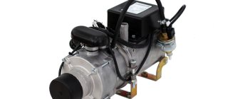
The heater is installed on the front cross member of the frame and consists of a heat exchanger 19 (Fig. Pre-heater) and a tilting burner.
The heat exchanger is welded with a “jacket”, inside of which a heated liquid, the coolant, circulates. A combustion chamber with a swirler 20 is inserted inside the heat exchanger. On the outer pipe of the heat exchanger, pipes 24, 25 for inlet and outlet of the heated liquid, pipe 23 for exhaust gases are welded.
A thermal fuse 29 and temperature sensors 30 and 31 are installed on the heat exchanger under the casing, which monitor the temperature of the liquid in the heater system and the vehicle cabin.
Sensor 30 controls the fluid temperature from (48±5)°С to (70±3)°С, sensor 31 - from (40±3)°С to (30±5)°С (maintains the thermal regime in the car cabin).
The thermal fuse turns off the heater when the maximum permissible liquid temperature in the heat exchanger is reached (103±5)°C (if sensor 30 fails, there is no water in the system, etc.).
The burner consists of a fan 5, a fuel pump 8, an injector 11, a solenoid valve 9, a flame indicator 15 and two ignition electrodes 12. The burner is used to create a torch and provide the necessary thermal conditions for the heated medium.
A fan with a plastic impeller and a 2 DC electric motor is designed to create air flow.
The 8-gear fuel pump is designed to supply fuel to the injector under pressure. The pump is driven by electric motor 2 through gear 7. Injector 11 sprays the supplied fuel. To increase the reliability of the nozzle, a sintered bronze filter is installed in front of the sprayer.
Electromagnetic valve 9 controls the supply of fuel from the fuel pump to the injector at the command of the control unit, depending on the operating modes of the heater.
The flame indicator 15 is installed on the disk 16 in close proximity to the nozzle and the flame and sends commands to the high voltage source, turning it on and off.
Two ignition electrodes 12 are located in front of the nozzle and ensure ignition of the heater due to a spark between them, formed when high voltage is supplied from the power source 28.
The burner is secured to the heat exchanger with hinged bolts and provides access to its elements during installation and maintenance. The burner is protected by a plastic casing on which is attached a high voltage source 28 and a suction pipe 3 for air intake.
Installation of ignition electrodes is carried out according to the template, as shown in Fig. Installation of ignition electrodes according to the template.
The circulation pump is installed on the front cross member and is designed to pump coolant through the heater.
The connection diagram of the heater to the engine cooling and cabin heating system (see figure) allows for optimal use of the heater's thermal energy by creating various coolant circulation circuits.
When the heater is operating, fuel is supplied to the injector by a pump under pressure. Excess fuel from the fuel pump returns to the heater tank. The fuel supply circuit for the heater is shown in the figure.
Heater device
The PZD includes the following elements:
- Radiator . This also includes the burner. The main element of the system with which the liquid is heated.
- Candle . This also includes additional elements. For example, a flame controller that regulates the heating strength and ensures the safety of the system.
- indicator . Works in conjunction with a swirler and an electromagnetic piston.
- Exhaust pipe. For proper operation, pumping equipment is used in conjunction with a harness.
- Regulator , cooler, fuel tank valve.
In some cases, additional equipment is installed on vehicles.
The heater can occupy one of four positions. Zero is when the device is completely turned off. It does not function at all, is not connected and does not work.
The first position is characterized by connected equipment and operating heating. The fuel goes straight to the burner, where it combines with air. The resulting substance ignites.
The second position is characterized by sending a flammable substance to a special combustion compartment. This is the main operating mode of the equipment. The substance lights up using a special torch.
The third position is characterized by preparatory work of the heater. The boiler is purged with ordinary air while heating the fuel.
The standard characteristics of the PZD for KamAZ guarantee 3,000 hours of operation.
PZD 15.8106 for KamAZ 65115
Using a specific model as an example, we will analyze the safety requirements during operation:
- You should understand how to use the heater by carefully reading the instructions, and remember: improper handling can lead to a fire.
- Do not use the heater if the cooling system is not full.
- Do not turn it on without fuel fluid.
- It is forbidden to open the burner during operation.
- Regularly clean the combustion air intake pipes from dirt and those going through the heater boiler to remove fuel combustion products.
- If electric welding work is planned on KamAZ, you should disconnect the six-pin connector on the PZD control unit.
- The negative terminal of the autonomous heater must be connected to the negative terminal of the battery, and not to ground.
- There should always be a working fire extinguisher in the vehicle interior.
- Always turn off the fuel valve after completing work.
Features of the operation of the Teplostar 14TS-10 PZD:
- It can operate in two modes: “economical” (ER) and “pre-start” (PR). In the first case, power consumption is reduced and allows you to complete a full cycle in 8 hours, while the operating time in pre-start mode is reduced to 3 hours.
- The system can be manually stopped at any stage of the cycle.
- The operation process of the autonomous heater 14TS-10 is controlled by the control unit.
- The temperature of the “autonomous” coolant is regulated depending on the selected heater operating program: “full” (70°C at WP, 55°C at ER), “medium” (70-75°C at WP, >55°C at ER ), or “small” (75-80°C at PR, 80°C at ER).
How does automatic control work in case of emergency situations:
- If 14TS-10 does not start, the control unit will automatically restart. If the second attempt is unsuccessful, the heater will turn off.
- If for some reason the combustion stops during operation, the heater will turn off.
- If overheating occurs (coolant circulation is disrupted or an air lock forms), the control unit will turn off the heater.
- When there is a sharp drop or surge in voltage, a shutdown also occurs.
In the event of an emergency shutdown of the diesel pre-heater, the LED on the control panel will light up, the number of blinks of which indicates the fault code. The explanation of errors and how to eliminate them can be found in the operating instructions.
What can you say about the control unit of the device?
The control unit guarantees control of the device together with the control panel. The block performs the following options:
- Initial diagnosis. The device and all its components are checked for malfunctions at start-up.
- Diagnostics of all processes directly during operation.
- Launch and automatic operation of the device in the “Economical” or “Pre-launch” programs. There is a transition to the above modes depending on temperature indicators.
- Turning off the device itself upon completion of the set cycle due to the loss of functionality of one of the components, when one of the parameters goes beyond acceptable limits, or when the flame in the chamber goes out.
Basics of operation of KamAZ railways
The KamAZ liquid heater works in conjunction with the vehicle’s heating equipment. At the same time, for the heater to work properly, a cooler must be present. Otherwise, the PZD will not be able to function.
The device receives power directly from the truck. As soon as the heater is turned on, a certain amount of fuel is sent. First, the electromagnetic pump turns on, and then the spark plug comes into play. The air comes into contact with the fuel through the nozzle, after which the hot candle provokes a fire. As soon as this happens, the candle turns off.
Combustion is maintained by constant contact of air with the combustible substance. Vapors of the hot substance come into contact with the walls of the heat exchanger. Exhaust gases are safely discharged through the exhaust pipe outside the vehicle.
The PZD can work even when the engine is turned off. There is no dependence of these devices on each other.
Error codes
Error codes PJ 14TS:
- If the LED blinks once, then the breakdown may be due to overheating of the heat exchanger or the temperature difference reported by the overheating and temperature sensors.
- If the LED element flashes 2 times, the error may be caused by the exhausted number of engine starts.
- The LED flashing three times is a preheater malfunction due to flame interruption.
- When the LED flashes 4 times, the problem may be a faulty spark plug or blower motor.
- 5 times means the flame indicator is broken.
- 6 times are errors in the operation of the overheating and temperature sensors.
- When the LED flashes 7 times, it is recommended to check the integrity of the circulation pump, fuel cell, control relay and heater.
- If the LED flashes 8 times, it means that the connection between the control panel and the control unit has been lost.
- 9 times - the voltage was turned off or reduced.
- 10 times - exceeding the time allotted for ventilation.
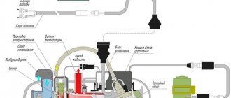
Connection diagram for PZD to KamAZ
1 – radiator of the car cooling system; 2 – coolant thermostat; 3 – car water pump; 4 – heat exchanger of the heating system; 5 – battery; 6 – heating system fan; 7 – fan switch; 8 – fuse block; 9 – heater; 10 – electric motor with pump; 11 - fuel line; 12 – electromagnetic fuel pump; 13 – fuel filter; 14 – timer – regulator; 15 - control unit for heater operation; 16 – relay for controlling the operation of the heating system fan; 18 – vehicle fuel tank; 19 – fuel tank; 20 – fuel supply valve for the heater.
PZD KamAZ is a liquid-type diesel heater.
Why doesn't it start
If the preheater does not work, the reason for this may be the following:
- The electric motor of the pumping mechanism does not start.
- The fuel liquid in the PZD boiler does not ignite.
- The fuse was turned off.
- Electric motor relay failure or switch failure.
- An open circuit that connects the wires between the relay and the electric motor.
- Malfunction of the engine itself.
- There is no spark between the spark plug electrodes.
- The overheating and temperature sensors failed.
- Disconnected or reduced voltage in the system.
- The spark plugs have failed.
- The blower motor was damaged.
- There is no communication between control systems.
- The number of engine starts has been exhausted.
- Overheating of heat exchange equipment.
- The flame indicator has failed.
- The supply pipe was damaged.
How to connect the railway to batteries on KAMAZ
We connect batteries to 24 volts
Kamaz, replacing the flame sensor.
Air suspension of the Kamaz cab, cut the cushions and see what's inside)))
autonomous stove KAMAZ
How to measure battery current leakage.
Ural use of EFU
Ammeter on the train
Teplostar 14 ts-10 for ZIL 4331 with YaMZ 236 engine
KAMAZ 4310, new
Glitch of the Planar 44D autonomous system or how to check the spark plug on the Planar heater.
Also see:
- Rear view camera for Hyundai Santa Fe 2011
- Automatic transmission for Volvo XC70 2001
- Test drive Mazda xedos 6 video
- Spare parts for Volkswagen Polo 2000
- Oil pressure insufficient Peugeot 307
- Compare Nissan Qashqai and Suzuki Grand Vitara video
- Hyundai Accent rear engine mount, automatic transmission
- Fuel pump relay for Kia sephia
- Wheels for Mercedes r18 amg replica
- Winch with cable laying device for KAMAZ trucks
- Mazda 3 speakers do not fit
- Chevrolet aveo or another name
- Toyota Cross 100 body tuning
- BMW X5 E70 glow plug block
- Volvo at dusk dawn 2
Home » New items » How to connect the railway to the batteries on KAMAZ
logovaz-auto.ru
Security measures
- Putting the pre-heater into operation and starting the engine is only possible if there is a sufficient amount of coolant in the system. Violation of this requirement can lead to boiler burnout, cracks in the cylinder liners and cylinder head, etc.
- Avoid oiling areas near the exhaust pipe of the heater boiler to prevent fire.
- The joint operation of the heater and the engine is unacceptable, because The flow of coolant during their operation is in the opposite direction. To avoid failure of the cooling system components and engine heating, it is necessary to first stop the heater and only then start the engine.
- It is not allowed to leave the motor grader while the heater is operating. If flame or smoke appears in the exhaust gases, immediately turn off the heater.
Principle of operation
The PZD is connected to the diesel engine cooling system. The system must be fully operational and filled with liquid in the required volume. When the diesel engine is turned on, fuel is supplied to its combustion chamber through a pump and a fuel pump and air, the fuel-air mixture ignites and begins to heat the engine cooling system liquid, which circulates around the combustion chamber body. The spent exhaust gases are discharged through its own exhaust system. After a few minutes, the temperature in the engine cooling system reaches an acceptable temperature for starting.
How to start
Instructions on how to start the preheater:
- Turn on the battery switch.
- Turn the valve on the fuel tank and fill the starting system with fuel fluid.
- Check the operation of the device using a special pump.
- Set the PZD switching handle to position III.
- Press the power button for the electric heating system.
- If the ambient temperature is above -40°C, then the time should be set to 60 seconds, and if -50°C and below, then 90 seconds.
- Move the switch handle to position I.
- Hold the control lever and wait for the characteristic hum in the heat exchange mechanism. This sound indicates that the burner has ignited.
- Release the lever.
If the hum is smooth, then all systems are working properly, but if not, then repair of the engine heating is necessary.
If the startup was unsuccessful, you need to move the switch to position 0 and repeat the procedure again after 1 minute. After 2 unsuccessful attempts, it is recommended to inspect the device for damage.
Starting the engine using a pre-heater PZD-30
Start-up must be done in the following order:
- Turn on the battery switch;
- Open the valve on the fuel tank of the heater and fill the heater power supply system with fuel, making several pumps with the manual fuel pump (see Fig. 10 and 11).
- Set the heater switch knob to position III and press the electric heater button (see Fig. 3) for a time depending on the ambient temperature: 60 s at temperatures up to minus 40 ° C; 90s - up to minus 50°C;
- Move the switch to position I and hold it in this position (no more than 30 s) until a characteristic hum appears in the heat exchanger, indicating that the fuel in the burner has ignited;
- Release the switch, which will automatically move to position II; a continued, even hum in the heat exchanger indicates that the heater is operating in a stable mode.
If the start of the heater fails, you need to turn the switch to position 0 and after 1 minute. repeat start. If after two attempts with switching to position I for 30 s with intervals between attempts of 1 min. If the heater does not start working, then you need to find the problem and fix it.
When the liquid in the engine cooling system warms up to 70-80°C, it is necessary to stop the fuel supply by setting the switch to position III. Then, after 15-20 seconds (after the flame noise in the boiler has completely stopped), you need to move the switch to position 0 and close the valve of the heater fuel tank.
After this, you need to start the engine by pressing the clutch pedal all the way.
Source
Errors and their elimination
When the Teplostar does not start or some part in it has failed, the first thing you need to do is inspect the connectors and contacts. Their characteristics are presented in the table:
Many faults are displayed as error codes.
Each of them has its own decoding. Thanks to such signals, you can fix the problem yourself. Error codes PZD 14TS-10 and their interpretation by the number of blinks from 1 to 10:
- Overheating has occurred in the heat exchanger. The system, using a semiconductor temperature and overheating sensor (SSD), shows +120°C. In this case, it is worth checking the operation of the pump and the functionality of the fluid circuit. If the difference is more than 20°, then change the sensor if necessary.
- All attempts to start have been exhausted, but the boiler does not want to start. In this case, you need to check how much fuel is in the system and how it is supplied. You also need to check the system in which the fuel burns and the pipeline that discharges exhaust gases.
- Flame interruption. The error indicates that you need to check the presence of fuel and its supply system. It is also worth inspecting the air supply system for fuel combustion. When the heating system turns on, you need to check the operation of the flame indicator and, if necessary, replace it. The filter installed on the fuel may be clogged.
- This error code 14TC-10 indicates that there are problems with the glow plug. Perhaps a fault in the motor is to blame. The supercharger wiring and spark plug operation should be checked. If necessary, components must be replaced.
- Flame indicator problem. The wiring needs to be inspected. It is worth checking the resistance of the indicator contacts: if the reading is more than 90 Ohms, an open is detected, less than 10 Ohms - a short circuit.
- The temperature and/or overheating sensor has become unusable. It's worth checking the wires. Most likely, you will have to replace the sensors.
- Failures in the circulation pump. If there is a break in the electrical circuits, then they need to be replaced. The short circuit must be repaired. If there are problems with the relay, it should be replaced with a new one.
- There is no connection between the remote control and the control unit. You need to carefully inspect the connectors and wiring.
- High/low voltage, the device has switched off. The battery, wiring, or voltage regulator must be repaired.
- The time allotted for ventilation has expired. The battery has not completely cooled down over a certain period of time. It is necessary to recheck the system supplying air to the fuel combustion chamber, and also replace the flame indicator.
Opinions about Teplostar are mostly positive. If you want to purchase it, then you should read the reviews and make sure that it is really necessary. The model range consists of the 11TS heater and 16 modifications of the 14TS. The manufacturer provides a guarantee for each device, but if instructions for proper operation are ignored, claims regarding malfunctions will not be considered.
instructions, 14TS-10, malfunctions, does not start, errors
The parking heater (in common parlance, autonomous heater) on KamAZ is used to heat the cab when the main engine is not running. Depending on the design, devices are divided into “dry” and “wet”. The first ones use a flame torch to heat the air that is supplied to the cabin, and the second ones heat the coolant of the car’s engine cooling system. In this case, the cabin is heated by a standard stove.
How does it work
The heater is an autonomous heat source and operates independently of the car engine. The device includes:
- burner;
- fuel pump;
- water pump;
- Control block;
- remote control panel;
- connecting wires.
The operating principle of the 14TS-10 heater is based on the transfer of heat from burnt fuel to a coolant pumped through a heat exchanger. The device is located under the hood and connected to the engine cooling system.
Before putting the autonomous heater into operation, an automatic check of the functionality of all its components is carried out. Having received information about the working condition, the control unit gives a command to ignite the device. At the same time, the circulation pump is turned on. There are 2 heater operating programs: “Economical” and “Pre-start”. The first one has lower power consumption, and the execution time is 8 hours. The second is more energy-intensive, but completed in 3 hours. You can stop the device manually at any stage of the cycle.
The fuel mixture is ignited after the combustion chamber is purged with air. A glow plug is used as a fire source, which remains in operation until the torch burns steadily. Diesel fuel is supplied to the combustion chamber by an electromagnetic fuel pump from its container or car tank. After heat is transferred to the walls of the heat exchanger, the exhaust gases are released under the car.
Automation ensures safe operation of the device and turns it off in the following cases:
- 2 unsuccessful startup attempts;
- flame torch failure;
- increase in network voltage more than 30 V and decrease below 20 V;
- heat exchanger overheating.
The first start-up and periodic switching on of the heater during the “Pre-start” program are carried out in the “Full” mode, and in the “Economic” mode - in the “Medium” mode. In this case, fuel consumption is 2 and 1.2 l/hour.
Malfunctions and their elimination
The organization of searching for defects is described in the operating instructions for the device. Malfunctions that arise during operation and require complete or partial disassembly of the heater must be carried out by specialists from repair organizations. All faults, except the inability to turn on the heater, are indicated by a blinking LED on the control panel.
Error codes
The heater is equipped with a monitoring system for the proper operation of components and individual elements. If a defect occurs, the automation classifies it and notifies the driver by the number of LED flashes. The list of possible malfunctions is summarized in a table indicating the necessary actions to be taken to restore the device to operability. Error codes correspond to the number of blinks of the indicator.
Malfunctions are collected into 10 groups based on the same causes of occurrence and methods for eliminating defects. The table is given in the heater operating manual.
Why doesn't it start
If, when you try to turn on the heater, the LED indicator does not light up and the start-up does not occur, then there may be several reasons for this situation, but they are all related to a lack of power:
- 25 A fuse blown;
- faulty electrical wiring;
- The contacts in the connectors have oxidized.
If there is power to the control panel, the cause of the malfunction may be a defect in any of the controlled elements. In this case, the defect code will be shown by a flashing indicator.
How to turn it on
Starting and changing operating modes of the “autonomy” are carried out from the control panel. To start the heater, you need to select a program using the mode key (3 or 8 hours) and turn on the power switch. The LED will light up and the control unit will begin executing the program. After testing is completed and the blower, pump and fuel pump are turned on, the burner will ignite. The program runs automatically and does not require driver intervention. At the end of the set time, the device will stop.
Restart is possible after a power failure; its subsequent activation - no earlier than after 10 seconds.
Repair
Despite the fact that the manufacturer recommends repairing breakdowns associated with disassembling an autonomous heater in specialized workshops, many drivers and car owners prefer to fix the faults themselves. The fairly high price of the work pushes them to this decision.
Most often, the flame sensor fails and the fuel line becomes clogged. The work is simple and does not require the use of special tools.
Regular scheduled maintenance will help reduce the number of defects.
For this type of heaters, there are 2 types of maintenance: daily and seasonal. The volumes, timing and list of work performed are given in the technical documentation for the device.
How to install
The 14TS-10 heater is installed on the frame cross member under the hood in front of the radiator. The device is mounted standard: bolted. The boiler's pipes cut into the standard cooling system. Fuel supply is possible from its own tank installed outside the engine compartment, or from the fuel system. Exhaust gases are removed through a corrugated metal hose under the bottom of the car between the cab and the body (trailer).
This placement of the autonomous unit allows for maximum removal of exhaust gases from the cabin, minimizing the length of the cooling system pipes and obtaining an additional heat source in the engine compartment.
specmahina.ru
PZD KamAZ - engine preheater, characteristics, analysis
During the cold season, car owners are forced to deal with the problem of freezing of the car and its fuel system. Endless temperature changes and dampness in winter can have a detrimental effect on the operation of the machine, rapid failure of parts and engine shutdown as a whole. To get rid of these problems, install an engine pre-heater or, in common parlance, a KamAZ PZD.
PZD-30 is installed on KamAZ vehicles and is a pre-starting liquid engine heater that is capable of operating unhindered at ambient temperatures from minus 45°C to plus 60°C. In this way, it is possible to simplify the task of owners in the fight against icing of glass, freezing of the cabin, and making it easier to start the fuel system of the car.
Important! Installing a PZD on KamAZ can not only reduce the wear of parts, but can also increase the service life of equipment and its units in severe frost.
Purpose of the heater
One of the features of a diesel engine is that it starts poorly at ambient temperatures below -15. -20°C. In cold weather, fuel and oil become too viscous, so the injectors cannot provide the necessary fuel atomization, and the crankshaft is difficult to turn. Therefore, to successfully start a diesel engine, it makes sense to use a pre-heater.
A heater is a special device that warms up the engine to a temperature at which it can start normally. In KAMAZ vehicles, a pre-heater is used to successfully start the engine at temperatures below -20°C. Some heater models can also warm up the cabin and other units, but this function is not used often, since it is not critically necessary.
Preheater operation
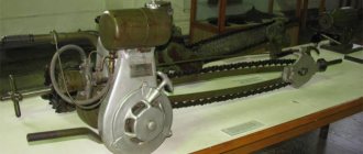
The operation of the KamAZ engine preheater, which is located under the front cross member of the frame (Fig. 1), is to supply fuel from the tank from the heater fuel pump.
Then the incoming fuel is directed through the open solenoid valve (1) to the nozzle and in a certain volume is injected into the internal burner of the heat exchanger (2) of the heater. The spread of fuel, mixed with the air from the operating fan, ignites and begins to burn, while heating the coolant. Next, the combustion products pass through the tube under the oil sump and increase the oil temperature.
Fuel in the heater tank appears during engine operation (4) from a special tank (5); if there is no fuel, then filling is possible using a manual fuel pump. It is necessary to regularly monitor for fuel and coolant leaks at the connections of pipes, valves and other components.
The pre-heater on KamAZ switches to purge mode when the boiler temperature reaches 85°C. It will be possible to re-enable the PZD at KamAZ after a complete shutdown.
Basic operating modes of 14TS-10
Using the regulator on the remote control, you can select one of three possible operating modes of the device, regulated by the control unit:
If the temperature drops to 55°C, the device automatically switches to the “Full” mode during the pre-start or “Medium” mode during the economical program.
The unit carries out preliminary and current diagnostics of 14TS-10, as well as control of specified operating modes. Using the remote control, the device is turned on, operating modes are selected and its parameters are controlled.
Pre-heater operating diagram
The operating diagram of the engine pre-heater looks like this:
Where: 1 control system; 2 DC motor; 3 suction tube; 4 coupling; 5 fan; 6 bearing; 7 gears; 8 fuel pump; 9 solenoid valve; 10.11 nozzle with housing; 12.13 ignition electrode and holder; 14 bypass valve; 15 flame supply indicator; 16 disk; 17,18 fuel outlet and supply pipes; 19,21,22 heat exchanger and its tubes; 20 swirler; 23 gas input/output tube; 24, 25 input/output tubes; 26.27 brackets; 28 power supply; 29 fuse; 30, 31 device control sensors.
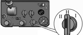
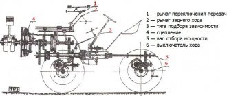
The PZD-30 remote control system makes it possible to control the operation of the heater both when the vehicle's cabin is in working position and when the cabin is overturned. The PZD-30 heater switch, mounted on a bracket in the cabin, has four positions:
- position 0 - everything is off;
- position I - the electric motor of the pump unit, the electromagnetic fuel valve and the electric spark plug are turned on;
- position II - the electric motor of the pump unit and the electromagnetic fuel valve are turned on;
- position III - the electric motor of the pump unit and the electric fuel heater are turned on.
Connection diagram for PZD to KamAZ
1 — radiator of the car cooling system; 2 — coolant thermostat; 3 — car water pump; 4 — heat exchanger of the heating system; 5 - battery; 6 — heating system fan; 7 — fan switch; 8 — fuse block; 9 — heater; 10 — electric motor with pump; 11 - fuel line; 12 — electromagnetic fuel pump; 13 — fuel filter; 14 - timer - regulator; 15 - control unit for heater operation; 16 — relay for controlling the operation of the heating system fan; 18 — car fuel tank; 19 — fuel tank; 20 — fuel supply valve for the heater.
Installation and repair of PZD
Important! It is better to install the PZD at specialized stations in order to avoid failure of vehicle systems or devices. Before the start of each cold season, it is necessary to carry out a technical inspection of the equipment.
The PZD-30 pre-heater device is started in a certain order:
- Activation of the battery switch - start by pressing the PZD switch button.
- Opening the valve on the fuel tank and filling the system with fuel in a KamAZ truck.
- Set the knob to position III and activate the heating start, taking into account the outside temperature.
- Move the handle to the reverse position I until the fuel ignites (characteristic sound).
- Automatic switching to steady heating mode
When the PZD is turned on, there is a stable hum in the system. This means that fuel combustion occurs in the heat exchanger and exhaust gases exit through the exhaust system without the formation of smoke or an open flame.
If disturbances occur in the operation of the KamAZ pump, you should initially adjust the fuel consumption using the pressure reducing valve. When changing and turning the valve to the right, the fuel supply increases, and to the left, it decreases. Depending on the stated requirements, it is necessary to set the lever to the optimal position. It is recommended to debug the fuel supply system depending on temperature changes. This will ensure not only more stable operation of the heating system, but also significantly reduce refueling costs.
Important! If you wash your car or water gets into the air fan, you need to remove it by turning the pump unit to position III for up to 3 minutes.
Functionality check
- Check the presence of antifreeze fluid in the engine cooling system
- Diagnosis of tightness of connecting nodes
- Electric heater diagnostics
- Bleed the fuel system manually
- Put the KamAZ PZD into action for 15-20 seconds
- Diagnosis of fuel leakage and presence of open flame
The PZD-30 engine pre-heater is a necessary device not only for comfortable and quick starting of a car engine, but also for saving fuel when warming up the cabin and fuel system, increasing the service life and wear of parts, the availability of the device (manufactured in the Russian Federation), and an affordable price.
Purpose of the device
In any KAMAZ 65115 or other modification, at temperatures below -15°C, a problem arises - the fuel acquires a viscous structure. Because of this, the engine injectors are not able to provide the necessary fuel spray, and the crank mechanism is very difficult to turn. That is why on KAMAZ one of the most useful additional devices is the pre-heater.
Before starting the engine, the device will warm it up to the optimal temperature, ensuring a stable start. As for the KAMAZ brand, in this case the device is mounted if the ambient air temperature reaches below -15°C. Some models are capable of performing several functions at once, including warming up the car cabin.
Unit features
For KAMAZ vehicles, autonomous liquid pre-heaters are used, which operate on diesel fuel. The main advantage of these variations is that they can provide effective engine warming up with minimal consumption.
Pre-heater KamAZ
It should also be noted that the device connects to the car’s electrical network, but does not consume a lot of electricity. It turns out that when using the KAMAZ preheater, the battery operates autonomously and does not require third-party power sources.
In more outdated truck models, simple devices of the 4310, 520 series are installed. These variations have a simple design and do not differ in complex installation schemes. Modern units are in great demand in new KAMAZ vehicles, buses, special equipment and tractors. But despite the difference in functions, the operating principle of the devices consists of standard steps.
VIDEO: Preheating a cold engine
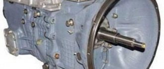
Design and device
The design of the KAMAZ pre-heater includes several main components:
- boiler room;
- burner;
- water pump;
- remote control device.
The main element is the boiler compartment, which consists of 4 durable cylinders that form a heat exchanger. This part includes 2 cavities that facilitate the unhindered passage of exhaust gas and coolant circulation. There are 3 tubes on the outer part of the engine heater, 2 of them are intended for draining or supplying antifreeze, one is for exhaust gas removal.
Pre-heater device
The exhaust gases hit the damped part of the boiler, which due to this action change direction and flow to the outlet pipe. In this case, thermal energy is consumed for heating in the engine sump.
On the reverse side, at the open end of the boiler compartment, a burner is mounted, which includes:
- spark plug;
- nozzle;
- valve;
- fuel heater;
- gas heater.
The pump is considered a separate unit that combines three main pumps - liquid, fuel, air. It is in this system that it differs from other types of pre-heaters.
For example, a modification of the PZD 30 heater has a pumping apparatus, which is designed as a separate unit. Such a device is installed both above the boiler room and in any most convenient place. In this case, the device is connected with hoses of different diameters and lengths.
Pumping unit design
Devices 15-8106 and other similar analogues are mounted on the edge of the boiler, near the burner. This installation option makes it possible to eliminate the need to use long hoses, which leads to a significant reduction in the dimensional parameters of the entire preheater.
Boiler heater design
The remote control device has an electronic unit, with the help of which the operating modes are configured in 4 main positions. This element also allows you to configure relays, various fuses, and a spark plug switch.
It should be noted that modern modifications in the design have a variety of controllers. First of all, users note the temperature and flame sensor. These elements make it easier to turn on the device and make it possible to fully control its operation.
Circuit diagram for switching on the engine starting heater
This eliminates the possibility of breakdowns requiring repair. But according to the principle of operation, these models of KAMAZ heaters do not have any special differences.
Recommendations for use
The key to a long service life of any equipment is compliance with the rules of use. In general, the following stages should be distinguished:
- Check the volume of coolant and fuel in the tank; if necessary, pump up or top up the mixture.
- The program regulator is directed to the fixed position “Three”. This action will start the fan and fuel mixture heater, and the boiler compartment will also be purged. At this moment, a portion of fuel is prepared for ignition. The operating time interval of the third program completely depends on the temperature regime of the atmospheric air: for -20°C you will need to hold it for only 25 seconds, -30°C - 35 seconds, -50°C - 1.5 minutes.
Connection diagram of the heater to the engine cooling system
- The program switch switches to the non-fixed “Two” mode. Here the valve at the inlet of the fuel pipe opens and the spark plug starts. The fuel is preheated under high pressure in the burner, at the same moment it is mixed with oxygen, forming a fuel mixture, which the candle ignites upon contact. As a rule, ignition is carried out in the first 15 seconds; when this mode is reached, a corresponding noise is generated.
- After the combustion chamber starts functioning, the “First” work program starts and is fixed. This task renders the spark plug inoperative, at which point the heater operates in main mode. The exhaust gases transfer their temperature to the coolant, and thanks to its circulation through the heater and the engine, it heats the power unit.
- When the temperature of the KAMAZ pre-heater reaches 70-80°C, the lever will need to be returned to level “Three”. This manipulation will allow you to close the valve on the fuel pipe without stopping the operation of the fan. As a result, the rotating element will completely purify the boiler from the remaining gases formed.
- After 30 sec. you need to turn on the “Zero” mode to completely stop the operation of the preheater. The final step is to close the solenoid fuel valve.
The preheater is considered a high hazard. If used incorrectly or made a mistake during installation, this particular device can become the primary cause of fire.
While the heater is operating, you need to stay nearby and ensure that no leaks form. If a liquid leak is detected, the device must be turned off immediately and not used until the problem is resolved.