IF THE TRACTOR SMOKES
If a tractor smokes, this may be due to:
- incorrect adjustment of the working fluid supply;
- motor overload;
- incorrect installation of the piston part;
- dirty air purifier;
- small advance angle of the fuel injection system;
- damaged injectors.
In these cases, engine repair using spare parts is required, and in some situations, overhaul.
If the smoke is black, it is recommended to reduce the load on the power unit or switch to first or second gear. It is also worth checking the nozzle holes of the spray mechanism with a needle, rinsing it, and if necessary, replacing it.
When white smoke pours out, you need to grind the valves or replace the heads of the cylindrical elements. The cause of white smoke may be water getting into the diesel fuel; in this case, it is necessary to drain the fuel fluid and add new one.
Blue smoke is a sign that piston parts such as rings and liners have been damaged.
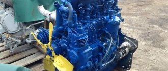
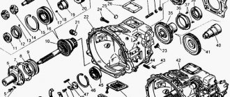
Bearings T-40, T-40A.
The universal row-crop tractors T-40M, T-40AM, T-40ANM were produced by the Lipetsk Tractor Plant from 1972 to 1995. The tractor is designed for processing and harvesting row crops, plowing light soils, pre-sowing treatment, sowing, hay harvesting, as well as for transport work. There were previous models: T-40 - 1961-77, T-40A - 1963-77. The high safety margin of the transmission and chassis components ensured the tractor high durability - most of the tractors produced in the 70s and 80s are still in use, both at enterprises and on private farms. The ongoing production of spare parts allows us to maintain these tractors in good technical condition.
Bearing table T-40, T-40A
| Installation location | Number | Bearing type | Size | Qty |
| Engine (flywheel) | 180204 | Ball radial single row | 20x47x14 | 1 |
| Starting motor PD-8 (gear wheel) | 202 | Ball radial single row | 15x35x11 | 2 |
| Starting motor PD-8 (crankshaft) | 205 | Ball radial single row | 25x52x15 | 2 |
| Starting motor PD-8 (crankshaft) | 42305 | Roller radial single row | 25x62x17 | 1 |
| Power regulator PD-8 | 202 | Ball radial single row | 15x35x11 | 2 |
| Single-section fuel pump 54.1111004-50 | 201 (46121209516) | Ball radial single row | 12x32x10 | 1 |
| Single-section fuel pump 54.1111004-50 | 6-25 (46111111065) | Ball radial single row | 5x16x5 | 2 |
| Single-section fuel pump 54.1111004-50 | 942/8 | Needle-shaped with one outer stamped ring | 8x14x12 | 2 |
| Single-section fuel pump 54.1111004-50 | 1000095 (46111170516) | Ball radial single row | 5x13x4 | 1 |
| Single-section fuel pump 54.1111004-50 | 29 | Ball radial single row | 9x26x8 | 1 |
| Single-section fuel pump 54.1111004-50 (cam shaft) | 204 (46121214329) | Ball radial single row | 20x47x14 | 1 |
| Single-section fuel pump 54.1111004-50 (cam shaft) | 304 (46121238320) | Ball radial single row | 20x52x15 | 1 |
| Single-section fuel pump 54.1111004-50 (cam shaft) | 29 | Ball radial single row | 9x26x8 | 1 |
| Cooling system | 180504 | Ball radial single row | 20x47x18 | 2 |
| Main clutch with PTO clutch (PTO release) | 9588213 (461993959604) | Ball thrust single row in casing | 65x99x21 | 1 |
| Main clutch with PTO clutch (clutch release) | 9588217 (461993960207) | Ball thrust single row in casing | 85x124x24.5 | 1 |
| PTO clutch shaft | 64706 (462532130903) | Radial roller with long cylindrical rollers without rings, single row | 29.9x42x41.1 | 1 |
| Gearbox (Slow Gear) | 305 | Ball radial single row | 25x62x17 | 3 |
| Gearbox (Slow Gear) | 102305 | Roller radial single row | 25x62x17 | 1 |
| Gearbox (primary shaft) | 406 | Ball radial single row | 30x90x23 | 1 |
| Gearbox (primary shaft) | 407 | Ball radial single row | 35x100x25 | 1 |
| Gearbox (secondary shaft) | 406 | Ball radial single row | 30x90x23 | 1 |
| Gearbox (secondary shaft) | 102211 | Roller radial single row | 55x100x21 | 1 |
| Gearbox with differential | 180107 | Ball radial single row | 35x62x14 | 2 |
| Gearbox with differential | 209 | Ball radial single row | 45x85x19 | 1 |
| Gearbox with differential | 212 | Ball radial single row | 60x110x22 | 1 |
| Gearbox with differential | 213 | Ball radial single row | 65x120x23 | 1 |
| Gearbox with differential | 102305 | Roller radial single row | 25x62x17 | 1 |
| Gearbox with differential | 102309 | Roller radial single row | 45x100x25 | 1 |
| Gearbox with differential | 42215 | Roller radial single row | 75x130x25 | 2 |
| Gearbox PD-8 (shaft) | 305 | Ball radial single row | 25x62x17 | 1 |
| Gearbox PD-8 (shaft) | 943/25 | Needle-shaped with one outer stamped ring | 25x32x25 | 1 |
| Gearbox PD-8 (shaft) | 180502 | Ball radial single row | 15x35x14 | 1 |
| Transfer case | 207 | Ball radial single row | 35x72x17 | 1 |
| Transfer case | 305 | Ball radial single row | 25x62x17 | 1 |
| Front drive axle (differential) | 213 | Ball radial single row | 65x120x23 | 2 |
| Front drive axle (main drive gear) | 209 | Ball radial single row | 45x85x19 | 1 |
| Front drive axle (main gear drive) | 310 | Ball radial single row | 50x110x27 | 1 |
| Front drive axle (crosspieces) | 804704 | Needle radial single row without inner ring and separator | 22x35x26.5 | 16 |
| Front drive axle (wheel steering axis) | 8115 | Ball thrust single | 75x100x19 | 2 |
| Front drive axle (final drive driven gear) | 311 | Ball radial single row | 55x120x29 | 2 |
| Front drive axle (final drive driven gear) | 409 | Ball radial single row | 45x120x29 | 2 |
| Front drive axle (final drive driven gear) | 7507 | Roller conical single row | 35x72x23 | 4 |
| Rear axle (final drive) | 315 | Ball radial single row | 75x160x37 | 2 |
| Rear axle (final drive, driven gear) | 2312 | Roller radial single row | 60x130x31 | 2 |
| Rear axle (final drive, drive gear) | 12309 | Roller radial single row | 45x100x25 | 4 |
| Front axle | 8208 | Ball thrust single | 40x68x19 | 2 |
| Front wheel hubs | 7608 | Roller conical single row | 40x90x35.3 | 2 |
| Front wheel hubs | 7609 | Roller conical single row | 45x100x38.3 | 2 |
| Steering (power steering housing) | 207 | Ball radial single row | 35x72x17 | 1 |
| Steering (bipod shaft) | 1207 | Ball radial spherical double row | 35x72x17 | 1 |
| Steering (hydraulic booster) | 304 (46121238320) | Ball radial single row | 20x52x15 | 1 |
| Compressor (crankshaft) | 112 | Ball radial single row | 60x95x18 | 1 |
| Compressor (crankshaft) | 60207 | Ball radial single row with one protective washer | 35x72x17 | 1 |
See also:
- Bearings VTZ-2427
- Bearings T-25A
- Bearings MB "Favorite" MB-3, MB-4, MB-5.
- Bearings for Bosch GWS 1400.
- Bearings MTZ-80
- Bearings T-16
- Bearings SB-640A, SB-640M, SB-640MD, “Buran”
- Bearings Zirka GN 121, Zirka GN 151.
- Bearings T-012 "KhTZ"
Construction of rear axles of wheeled tractors
The rear axle of the MTZ-50 and MTZ-52 tractors has a cast iron body 21 (Fig. below), reinforced with internal partitions.
Rear axle of the MTZ-50 tractor:
1— final drive driven gear; 2, 4 and 7 - bearings; 3 — splined bushing; 5 - axle shaft; 6 — oiler; 8 — axle sleeve; 9 — brake casing; 10 - cover; 11 — brake discs; 12 — final drive drive gear; 13 — brake ball; 14 — pressure plates; 15 — cylindrical roller bearings; 16 — adjusting shims; 17 - glass; 18 — tapered roller bearing; 19 — BOM shift clutch; 20 — BOM drive shaft; 21 — body; 22 — drive gear of intermediate gear; 23—adjusting washer; 24 — secondary shaft of the gearbox; 25, 30 — satellite axis; 26 - thrust steel washer; 27 — semi-axial gear 28 — bronze thrust washer; 29 — satellite; 31 — differential housing; 32—intermediate gear driven gear 33—differential lock pedal; 34 — fixed cam clutch differential lock; 35, 45 — spring 36 — lever; 37 — rod, 38 — cover; 39 — earring; 40 — movable cam clutch differential lock; 41 — pedal 42 — rod for fixing the brake pedal; 43 — adjusting rod; 44 — bar
In front, the gearbox housing is bolted to it, and on the sides are the sleeves of 8 axle shafts. The housing houses the intermediate gear, differential, final drives and PTO planetary gearbox.
The intermediate gear consists of two bevel gears with spiral teeth: a drive gear 22, mounted on the splines of the secondary shaft 24, and a driven gear 32, attached to the differential housing.
The differential is closed . Its body 31 is composed of two cups, between which the axes of the satellites 25 and 30 are clamped. Four satellites 29 are put on the axle, which are in constant mesh with two semi-axial gears 27. The satellites are pressed against the body through steel thrust washers 26, and the semi-axial gears - through bronze washers 28.
The differential rotates in tapered roller bearings 18, pressed into cups 17, which are inserted into the bores of the side walls and internal partitions of the housing. Steel spacers 16, placed between the cup flange and the rear axle housing, serve to adjust the bearings and engage the intermediate gear bevel gears. The cups also contain drive gears 12 of the final drives, manufactured as one piece with shafts that rotate in cylindrical roller bearings 15. The internal splined ends of these shafts are connected to the differential side gears.
In the cups 17 against the driving gears 12, slots are made through which the driven gears 1 of the final drives engage with these gears. The driven gears are put on the splines of the bushings 3, which rotate on bearings 2 and 4. The splined ends of the axle shafts 5 are passed through the bushings. The other ends of the axle shafts rest on ball bearings 7, pressed into the sleeves 8.
Inside, on the axle shaft there are cam clutches of the differential locking mechanism: fixed 34 and movable 40. When you press the pedal 33, the rod 37 rises up and through the earrings 39 turns the lever hingedly attached to the cover 38. The fork of the lever moves the clutch 40, connected to it by pins, to the right and connects to coupling 34, so both axle shafts rotate as one. When you stop pressing the pedal, spring 35 returns the parts to their original position.
The rear axle mechanisms are lubricated with automotive oil AK-15 (in summer) and AKP-10 (in winter). It is poured through the hole in the gearbox cover. From the cavity of the box, oil enters the cavity of the rear axle. Penetration of oil to the brakes and into the axle sleeves is prevented by oil seals.
Disc brakes are placed in cast housings 9, attached to the rear axle housing. Together with the shaft of the final drive drive gear, two brake discs 11 with friction linings rotate. Between them there are two pressure disks 14, tightened by springs. Five balls 13 are placed between the pressure disks in the holes facing each other.
When one of the pedals 41 is pressed, the bars 44, following the rod 43, turn the pressure disks in different directions. The inclined surfaces of the holes slide over the balls 13 (see Fig. c), the pressure disks diverge, lightly press the brake disks against the casings 9 and the cover 10 and slow them down. At the same time, the disks themselves begin to rotate.
However, the disks move together only until the tide of one of the pressure disks reaches stop A - forward movement (see Fig. b) or until stop B - backward movement. After this, only one pressure plate turns, the balls expand the disks even more and increase braking.
The brakes are adjusted by changing the length of the rods 43 so that the full pedal stroke is 80-100 mm with a force of 12 kgf. To ensure that the brakes operate simultaneously, it is important to set the travel of both pedals to the same level. If the total wear of the discs exceeds 8 mm, the friction linings are replaced.
Rear axle of tractors T-40 and T-40A . The intermediate gear and differential of these tractors are placed in the same housing with the gearbox, to which the final drives are connected through sleeves. The intermediate gear is double, its bevel gears 3, 5 and 11 are located ahead of the gearbox, and cylindrical gears are located after it. The drive gear 49 is attached to the secondary shaft, and the driven gear 47 is attached to the differential housing 43.
The differential housing rotates on cylindrical roller bearings 42. Inside the housing there are two satellites 4b on a common axis 44 and side gears 48.
To lock the differential, press the pedal 29. At the same time, the rod 33, rising by the lever 30, turns the fork 38, which moves the gear coupling 40 along the splines of the axle shaft 39. The coupling engages with the internal teeth of the hub of the differential housing cover and thus connects it to the axle shaft. When you stop pressing the pedal, the rod spring returns all parts to their original position.
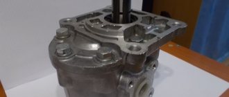
Final drive of the T-40 tractor:
a - final drive; b - seal; 1 - shaft with drive wheel flange; 2 - mechanical seal; 3 - body; 4 - coupling bolt; 5.7 - cylindrical roller bearing; 6 - drive gear; 8 — oil seal; 9, 11 — brake rod; 10 - spring; 12— brake pedal; 13 — brake drum; 14 — brake band; 15 — sleeve flange; 16 - cover; 17 — axle shaft; 18 — brake lever; 19 — brake roller; 20 — adjusting nut; 21 — brake band lever; 22 — thrust; 23 — axle sleeve; 24 - cover; 25 — roller bearing; 26 - bolt; 27 and 28—glasses; 29 — driven gear; 30 - pallet; 31 - ball bearing; 32 — plate with pins; 33 - plate; 34 — shields; 35 - thrust ring; 36 - pin; 37—spring; 38 — pressure ring; 39 - diaphragm
The final drives on tractors are mounted in cast housings 3, which are fixed relative to the hose flanges by 23 mounting pins and bolted to them. The drive gear 6 rotates on cylindrical roller bearings 5 and 7. Its splined shank is inserted into the hub of the brake drum 13, riveted to the flange of the axle shaft 17. The axle shaft and gear are tightened with a long bolt 4, passed through a drilling in the gear. This connection makes it easy to disconnect the final drive from the axle sleeve, for example when changing the ride height.
The driven gear 29 is mounted on the splines of shaft 1, manufactured together with the drive wheel mounting flange. The shaft rotates in 31 ball and 25 roller bearings.
The final drive parts are lubricated with oil poured into the housing to the level of the filler hole. Penetration of oil into the sleeve is prevented by oil seal 8. The same oil seal is installed in cover 16.
Oil leakage through the gap between shaft 1 and the housing, as well as the penetration of dirt into the final drive, is prevented by the mechanical seal 2. The pressure ring 38 is pressed against the thrust ring 35 of the seal, mounted on shaft 1, by means of springs 37, which is held from rotation by pins 36. Joints of the rings carefully polished and ground together.
The pressure ring is connected to a diaphragm 39 made of oil-resistant rubber. The plate 33 and shields 34 protect the diaphragm and form a labyrinth that reduces the penetration of dirt to the oil seal.
Band brakes with two tightening ends. The brake drum 13 is covered by a steel band 14 with a friction lining. Both ends of the tape are attached to a lever 21 fixed to the inner end of the roller 19, and a thrust bolt keeps the tape from sagging. When the pedal is pressed, the movement from its lever 12 through rods 11 and 9 is transmitted through lever 18 (Fig. below) and roller 19 to lever 21. When lever 21 is turned, the ends of the tape are pulled together, it is pressed against the pulley and slows it down. The release is carried out due to the force of the spring 10 and the elasticity of the tape itself.
T-40 tractor brake diagram:
40 - thrust bolt. The remaining symbols are the same as in Fig. higher
The pedal stroke until the tape is fully tightened should be 50-80 mm. If it increases as a result of lining wear, the brakes are adjusted. To do this, screw nut 20 until it stops, and then loosen it 3.5 turns and lock it with a lock nut. The uniformity of the gap distribution around the circumference of the tape is adjusted with a thrust bolt 40, it is screwed in until it stops, released 3/4 of a turn and locked with a lock nut. The simultaneous action of both brakes is regulated by changing the length of the rods 9 so that in the uppermost position of the pedals their grooves are located in the same plane and can be freely connected by a locking latch.
The rear axle of the T-16M self-propelled chassis is similar to the rear axle of the T-40 tractor. It is distinguished by its smaller size and some features of the device: the axle shafts are made together with the drive gears of the final drives, the differential rests on ball bearings and is locked by a cam clutch. The shafts of the driven final drive gears rotate on tapered roller bearings. The normal clearance in bearings is 0.1-0.3 mm. To reduce the gap under the flange of the inner bearing cup, steel shims are added. The shaft should rotate easily and at the same time not have noticeable longitudinal movement.
The brakes are simple band brakes, with separate controls. If necessary, both brake pedals can be locked with a latch. The travel of the pedals until full braking (75-100 mm) is regulated by changing the length of the connecting rods, and the uniformity of the gap distribution around the circumference of the belt is controlled by thrust bolts in the axle shaft sleeves. These bolts are screwed in until they stop and, after unscrewing 3/4-1 turn, they are secured with locknuts.
Rear axle of the T-25 tractor . The differential is placed behind the secondary shaft 16 (see Fig. 122) of the gearbox and receives rotation from it through gears 20 or 25, which are riveted to the differential housing 22. Inside the housing there are two satellites 23 on the axis 24 and two side gears 22. The differential rotates in two ball bearings installed in cups 21. There is no differential locking mechanism on the T-25 tractors. Oil leakage from the power transmission housing into the axle shaft sleeves is prevented by self-clamping oil seals installed in the cups.
The final drives are attached to the body with sleeves. The fastening design allows you to rotate the final drives relative to the sleeves to change the ground clearance.
The brakes are mounted on axle shafts and are made according to the diagram shown in Fig. 127.6. The gap between the belt and the drum is adjusted using thrust bolt 1 and limit bolts 14. To obtain the required gap, all bolts are screwed in all the way, unscrewed 1.5-2 turns, and then locked with lock nuts. In this case, the spherical nut 13 should touch the recess in the pedal lever, and the pedal stroke before full braking should be 50-60 mm.
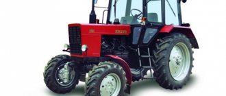
contents .. 1 2 3 ..DEVICE OF TRACTOR T-40, T-40A
The T40 universal tractor is made according to the usual design for tractors.
The tractor frame consists of: a half frame, a clutch housing, a transmission housing, sleeves and final drive housings.
Rice. 1. T40 tractor on the right - front.
In front of the engine, the following are mounted on a bracket: power steering, air cleaner and hydraulic tank.
All components and mechanisms located at the front along with the engine are covered by the hood.
The clutch mounted on the engine flywheel is a dual clutch and includes the main clutch and the power take-off shaft clutch.
At the rear of the clutch housing there are drive and control mechanisms for the rear and side power take-off shafts.
The rear and side power take-off shafts can be used with either independent or synchronous drive.
The transmission, final drive, differential, differential lock, and transmission control mechanism are located in one common housing called the transmission housing.
Rice. 2. T40A tractor on the right - front.
On the left and right sides of the transmission housing there are sleeves in which the brakes are placed. The final drives are attached to the sleeves.
The drive wheels of the tractor, equipped with pneumatic tires, are mounted on the axle shafts of the final drives.
To increase the traction weight of tractors, weights are installed on the rear wheel disks and a mechanical additional loader is used (rearranging the central link on the bracket).
To increase the longitudinal stability of the tractor, it is possible to move the loads from the rear wheels to a bracket fixed in the front part of the tractor.
A single-seat, sprung tractor driver's seat with a hydraulic shock absorber and a fuel tank are installed between the rear wings. A tool box is installed on the protective sheet behind the seat.
Tractors are equipped with a hydraulic system, which includes: a distributor installed on the rear wall of the battery box on the right side of the tractor: an oil pump with a drive located on the left side in front of the engine; oil tank mounted on the hydraulic booster bracket; main cylinder installed under the fuel tank on the left side of the tractor; a linkage mechanism located on the rear plane of the transmission housing, as well as pipelines and hoses for connecting components and assemblies of the hydraulic system and leads to remote cylinders. The hydraulic power steering is connected to the oil pump of the hydraulic system through a flow valve, making it easier to control the tractor.
The tractor's electrical equipment includes batteries, four headlights, a taillight, signal and instrument panel lighting lamps, a generator, a relay regulator, a fan, a lamp, a sound signal, switches and wires.
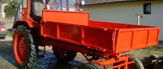
When working on transport, the tractor is equipped with a hydraulic trailer hook.
contents .. 1 2 3 ..