How to start a bulldozer t 170 video
Many tractor drivers traditionally call the T-130 bulldozer T-100 or “weaving”. In fact, the model was a deep modernization of the T-100 tractor. T-130 is a powerful tracked industrial bulldozer with a mechanical or hydromechanical transmission, belonging to the 6th traction class.
It was used as part of a bulldozer-loosening unit, used for the first plowing of uncultivated lands, deep plowing, harrowing, and transport work. The T-130 was the basic machine for the pile driver and pipe layer.
The main advantages of this equipment were the availability of spare parts, low cost and simplicity of design, allowing repairs to be carried out quickly and easily. Despite the obsolescence and wear of individual parts of the bulldozer, it can safely be classified as a “workhorse”.
Even now, T-130 models from the 1970s can be found on construction sites. The disadvantages of the model include unreliability of clutches and imperfect design. In comparison with models produced by foreign enterprises during the same period, the T-130 Engine was noticeably inferior to them in most respects.
It was quite difficult to start the bulldozer in low temperatures. However, simple maintenance and low cost did their job - the machine became widespread in the USSR and Russia. The T-130 was produced by the Chelyabinsk Tractor Plant. The model existed from 1969 to 1988, after which its production ceased.
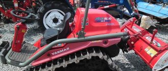
In addition to the classic version, the bulldozer came in a swamp modification - T-130B. It differed from the traditional larger track area, providing improved cross-country ability and low ground pressure. The T-130 model, the D 160 engine, was replaced by the T-170 version with significant modifications to the body and a new engine.
Technical characteristicsThe engine power of the T-130 bulldozer is 117.7 kW (140 “horses”). The specific fuel consumption of this model is 244.3 g/kWh (180 g/l. h.). At the same time, the bulldozer’s fuel tank holds up to 290 liters of fuel; the machine consumes exclusively diesel.
With a structural weight of the bulldozer of 14.32 tons, the specific pressure on the ground is 0.5 kg/1 cm2. Overall dimensions of the T-130: 5193 by 2475 by 3085 millimeters. The ground clearance of the model is 415 millimeters, the track width is 1880 millimeters.
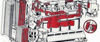
Device The T-130 bulldozer was equipped with a four-stroke diesel engine D-130 (power 140 “horses”), which became obsolete already in the 70s. Since 1981, the model began to be equipped with an improved four-cylinder D-160 engine with turbocharging (160 hp). It was started using a gasoline engine. This installation was received by a significantly modernized version of the T-130 - the T-170 bulldozer.
The model received an 8-speed manual transmission, including a clutch (permanently closed), four discs (two driven, two driven) and a four-shaft gearbox. Bulldozers of this type were equipped with a floating, band brake system.
The ability to mount a power take-off shaft made the T-130 universal, allowing it to be used with a variety of equipment for many industries. The cabin in this model is located at the rear and is designed for two people.
It has sound and thermal insulation, which allows you to “smooth out” unpleasant conditions outside and make working with equipment more comfortable. But the control of the bulldozer is far from ideal. During operation, a strong vibration emanating from the control levers is clearly felt.
This is due to their direct connection to the transmission.
How to start a bulldozer t 170 video
Operation of the T-170 tractor during forest fire extinguishing exercises. As you can see, the bulldozer copes perfectly with...
Operation of the T-170 tractor during forest fire extinguishing exercises. As you can see, the bulldozer copes well with such tasks.
Tractor.T-130. ... T-130 ringleader mudilovo. …. Kirovets drags a T-170 (MOVIE ABOUT THE FILM) - K-701 tractor towing a T-170 - Duration: 9 ...
Andrey with the launcher
Vladimir Manually a trifle from a moped, and they already have the main engine.
Mikhail First, the gasoline starting engine is started with an electric starter, then the main diesel engine is started with its help.
Bulldozer T-130 technical specifications, video, photo..
Many tractor drivers traditionally call the T-130 bulldozer T-100 or “weaving”. ... At low temperatures it was quite difficult to start the bulldozer. However... The T-130 model was replaced by the T-170 version with significant...
Bulldozer t 130 starter for launcher » Automotive portal for..
... bulldozer T-130. How to start a bulldozer with a dead battery... So this is on more serious bulldozers, T-130; T-170. Launcher for the T-130 bulldozer... through our website. launcher for a bulldozer - video NofolloW.Ru
Source: https://uvlechenie.info/chto-kak-pochemu-4/kak-zavesti-buldozer-t-170-video.phtml
Regulation of starting motor mechanisms T-170 B-10 D-160 D-180
here you will find information: about tractors T-170, T-130, B-10, and their mounted attachments, cabins of old and new cabins T-130, T-170, B-10, power plants engines D-160, D -180, caterpillar undercarriage T-170, B-10, bogie frame T-130, T-170, B-10, spare parts spare parts T-170, T-130, B-10, read articles about the repair of T- bulldozers 130, T-170, B-10.
Adjusting the gaps in the timing mechanism of the starting engine (Fig. 8.9)
| carry out on a warm engine in the following sequence: – turn the crankshaft with the handle until the “TDC-1C” mark of the flywheel coincides with the mark “1” on the flange of the clutch hatch on the compression stroke of the first cylinder (to reduce compression, unscrew the spark plug); – use a feeler gauge to check the gap between the head of the adjusting bolt and the end of the valve stem of the first cylinder. The normal gap is from 0.2 to 0.25 mm. If necessary, adjust the gap by rotating the adjusting bolt, after loosening the lock nut. After tightening the locknut, check the clearance again; – remove the spark plug, set the piston of the second cylinder to top dead center on the compression stroke and adjust the clearances as indicated above. | Rice. 8.9. Adjusting the gap in the timing mechanism of the starting engine: 1 – valve pusher; 2 – nut; 3 – adjusting bolt; 4 – valve stem; 5 – gap between the adjusting bolt and the valve stem |
Adjusting the carburetor throttle drive . The length of rod 1 (Fig. 8.10), connecting the throttle valve to the regulator lever, must ensure that the damper moves from the full open position to the full closed position when moving the regulator lever. To do this, by rotating the clutch on the rod, set the length of the rod so that when the carburetor throttle is fully open, the regulator lever is in the extreme left position. Then reduce the length of the rod by 4–8 mm and tighten the locknut of the threaded coupling.
Adjusting the carburetor choke control drive:
– disconnect rod 6 (Fig. 8.10) from the air damper lever;
– check the fastening of the rod shell, tighten if necessary;
– set the handle of the choke rod 36 (Fig. 3.9) to the extreme forward position and connect the rod to the carburetor choke lever.
| Rice. 8.10. Starting motor control: 1 – throttle control rod; 2, 4, 7, 8, 10, 12 – lever; 3, 5, 9, 11 – thrust; 6 – air damper control rod |
Regulating the quality of the combustible mixture.
When installing the carburetor on the engine, screw screw 2 (Fig. 8.11) all the way (without using excessive force) and turn it out 1.5–2 turns, carry out further adjustments with the engine running.
At minimum idle speed, tighten screw 2 to ensure stable engine operation. The normal screw position is 1–1¼ turns from the fully tightened position.
Regulating the crankshaft speed of the starting engine.
Adjust the minimum crankshaft rotation speed using screw 12 (Fig. 8.11) to limit the throttle valve stroke when screw 2 is in the adjusted position.
To adjust the minimum idle speed:
– tighten screw 2 until it stops (without using excessive force) and unscrew it 1.5–2 turns;
– tighten screw 12 1.5–2 turns from the position at which the throttle valve begins to open. Start the engine and let it warm up;
– holding the throttle valve in the closed position, slowly turn out screw 12, reducing the crankshaft speed until the engine starts to work intermittently, after which screw 12 in, setting the minimum stable speed;
– turn off the starting engine and start. If the engine operates unstable, repeat the adjustment using screw 12.
Before adjusting the maximum speed, it is necessary to adjust the length of the throttle linkage (see Adjusting the throttle drive).
The maximum idle speed is adjusted by changing the tension of the regulator spring using the adjusting screw nut. Increasing the spring tension increases the rotation speed, and decreasing the tension decreases it.
The maximum crankshaft rotation speed at idle is 2800 ± 50 rpm.
After adjustment, lock the adjusting screw nut.
| |
| Rice. 8.11. P-23U starting engine (cross section): 1 – throttle lever; 2 – screw for regulating the quality of the combustible mixture; 3 – wire; 4 – spark plug; 5 – cover; 6 – filter element; 7 – body; 8 – oil deflector; 9 – air damper lever; 10 – rod shell clamp; 11 – carburetor; 12 – throttle valve travel limiting screw; 13 – collector; 14 – cylinder head; 15 – valve sleeve; 16 – valve; 17 – cover; 18 – adjusting bolt; 19 – lock nut; 20 – valve pusher; 21 – plug; 22 – turning mechanism; 23 – oil measuring line of the starting engine; 24 – camshaft; 25 – plug; 26 – gearbox oil gauge; 27 – plug; A – gap 0.2-0.25 mm; B – oil level to the lower edge of the oil deflector |
Adjusting the clutch of the starting engine (Fig. 8.12) is necessary in cases of slipping of the disks, as well as if the gears of the gearbox are switched (ACCEPTATE, SLOW) and the engagement of the gear of the engagement mechanism with the rim of the diesel flywheel occurs with impacts of the teeth.
Disc slipping occurs either from wear of the rubbing surfaces of the discs or from their oiling.
If the rubbing surfaces of the discs become oily, they must be washed as indicated in subsection 7.7.
For wear adjustment:
– disengage the clutch;
– unscrew the bolts securing the side hatch cover and open the hatch;
– rotate the crosspiece 8 (Fig. 8.12) around its axis so that access to the latch 3 of the crosspiece is created through the hatch;
Rice. 8.12. Clutch and gearbox with clutch engagement mechanism:
1 – body; 2 – gear; 3 – latch; 4 – body; 5 – plug; 6 – disk; 7 – shaft; 8 – cross; 9 – fixed disk; 10 – pressure disk; 11 – coupling; 12 – clip; 13 – brake; 14, 15 – gear; 16, 19 – spring; 17 – latch; 18 – screw; 20 – clutch of the activation mechanism; 21 – pusher
– move the crosspiece latch button back until it comes out of the hole in the pressure plate 10;
– holding the pressure plate, rotate the cross until the latch enters the adjacent upper hole in the pressure plate. In this case, the clutch crosspiece will approach the pressure plate;
– turn the clutch on and off several times, move the cross another hole and repeat the activation.
When a properly adjusted clutch is engaged, the torque on the lever axis 2 (Fig. 8.10) should be from 50 to 70 Nm (5 to 7 kgfm).
When a properly adjusted clutch is engaged, the resistance on the engagement lever initially increases, and at the end of engagement, a click is heard from the closure of the pressure mechanism.
Shockless engagement of the gearbox gears is possible with effective braking of the clutch shaft, which is achieved by correct regulation of the clutch control drive.
Adjusting the clutch control drive (Fig. 8.10):
– disconnect rod 3 from lever 4;
– turn lever 2 clockwise until it stops;
– set lever 34 (Fig. 3.9) to control the clutch forward until it stops;
– align the holes in the fork of the rod 3 (Fig. 8.10) with the hole in the lever 4 and, lengthening the rod by 3–5 mm, connect it to the lever 4 and lock it.
When you turn the clutch on and off, you should hear a characteristic click.
Adjusting the gearbox drive (Fig. 8.10):
– disconnect rod 11 from lever 12;
– set lever 12 to the engaged overdrive position (lower position of the lever);
– install lever 37 (Fig. 3.9) to shift the gearbox forward until it stops;
– align the holes in the fork of the rod 11 (Fig. 8.10) with the hole in the lever 12 and then, lengthening the rod by 3–5 mm, connect it to the lever 12 and lock it.
The lever positions ACCELERATELY and SLOWLY are fixed. Turn the lever slowly to feel it lock. If the engagement does not occur when turning (the teeth of the gears rest), turn the engine shaft by engaging the clutch with lever 34 (Fig. 3.9), and repeat the engagement.
Adjusting the starting motor activation mechanism
With the spring tension correctly adjusted, gear 15 (Fig. 8.12) of the activation mechanism is disengaged from the flywheel ring automatically when the diesel engine reaches a rotation speed of 279 to 290 rpm. Adjust the rotation speed of the gear by changing the tension of the spring 19 of the latches 17 of the clutch of the activation mechanism with screws 18.
If the tension of spring 19 is weak, gear 15 is switched off prematurely, i.e., it disengages before the diesel engine starts working. If the spring tension is strong, there is a delay in turning off the gear, which can lead to a breakdown of the starting motor. One turn of the adjusting screw 18 of the spring approximately corresponds to a change in the rotation speed of the diesel crankshaft by 50–100 revolutions per minute, at which the gear is turned off.
After adjustment, tighten the latch screws.
Adjusting the drive of the drive gear engagement mechanism (Fig. 8.12).
For regulation:
– disconnect rod 9 (Fig. 8.10) from lever 10;
– set lever 35 (Fig. 3.9) of the activation mechanism forward until it stops;
– turn lever 10 (Fig. 8.10) clockwise until it stops (the switching mechanism must be in the off position). In this position, adjust the length of rod 9 and connect it.
Installing a magneto and starting motor ignition Before installing the magneto, check and, if necessary, adjust the gap between the breaker contacts:
– remove the cover from the magneto;
– loosen the screw securing the contact stand;
– turn the eccentric to set the required gap;
– tighten the screw securing the rack;
– check the size of the gap, which should be in the range from 0.25 to 0.35 mm.
When installing the magneto on the engine, align mark 2 “Clamp” (Fig. 8.13a) with mark 1 on the flange of the clutch housing hatch, slowly turning the flywheel as it rotates.
Rotate the magneto shaft so that slot 11 (Fig. 8.13c) on the starting accelerator body, when viewed from the flange, is on the left side of the vertical axis 8, and the axis of the cams 6 should pass beyond the vertical axis of the magneto at an angle from 5° to 10° along the rotation. In this position, install the magneto on the engine and check the ignition timing.
Rice. 8.13. Installation of magneto and ignition of the starting engine:
1 – mark on the clutch housing; 2 – mark “ZAZH” on the flywheel; 3 – slider; 4 – slider contact; 5 – terminal designation; 6 – axis; 7 – the angle between the vertical axis of the magneto and the axis of the cams is 5–10°; 8 – vertical magneto axis; 9 – arrow of the direction of rotation of the magneto rotor; 10 – starting accelerator cam; 11 – slot on the starting accelerator; 12 – “TDC-1C” mark on the flywheel; a – installation of ignition of the starting engine on the flywheel; b– rear view of the magneto; c – front view of the magneto
To check and adjust the ignition timing:
– slowly turn the flywheel as it rotates until the starting accelerator clicks on the compression stroke in the first cylinder, then turn in the opposite direction so that mark 2 “Clamp” (Fig. 8.13a) coincides with mark 1 on the hatch flange of the clutch housing;
– remove the distributor cap;
– check the position of the magneto breaker contacts, which should be at the beginning of opening. If the position of the contacts does not correspond to the specified one, loosen the nuts securing the magneto and, turning it relative to the studs, set the contacts to the position where the opening begins;
– secure the magneto in this position.
To check the serviceability of the magneto you must:
– having disconnected the wires from the spark plugs, bring their ends closer to a distance of 5 to 7 mm to the magneto body;
– sharply turn the crankshaft of the starting engine using the starter or crank. When the magneto is working properly, a spark occurs between the magneto body and the ends of the wires. If there is no spark, clean the magneto contacts, adjust the gap between the breaker contacts and repeat the test.
Before checking the serviceability of the spark plugs, it is necessary to unscrew the spark plug, clean it of carbon deposits, wash it in gasoline and wipe it. Inspect the surface of the insulator and the spark plug gasket. Check and, if necessary, adjust the gap between the spark plug electrodes. The gap should be from 0.6 to 0.7 mm (adjust by bending the side electrode).
To check the serviceability, connect the wire from the magneto to the spark plug, place its body on the starting motor, and turn the starting motor shaft using the starter or handle.
Check the quality of the spark - the spark should be bright, light blue in color and accompanied by a characteristic crackling sound.
ALL ARTICLES
Tractor T-130. Overview, characteristics, application and operation features
The T-130 tractor is a Soviet design, a caterpillar tractor produced by the Chelyabinsk Tractor Plant from 1969 to 1988.
It is a deep modification of the even more famous T-100 model, also known as “weaving”.
The scope of application of the T-130 was very wide, the device was used both for agricultural work and for work of industrial specifications.
Purpose of T-130
The T-130 tractor could perform the following operations:
- pipe laying;
- transportation of goods;
- plowing;
- hilling;
- harrowing;
- functioning as part of a pile driver;
- loosening the soil (bulldozer function);
- working with a loader bucket;
- dragging loads (for example, on logging sites).
The machine was used as an independent element and as a component of bulldozer units.
Distinctive features
- simple design;
- moderate cost in comparison with models produced at the same time (or foreign analogues, which were in short supply in the USSR);
- simple control mode;
- heavy weight, power, good cross-country ability (including the presence of a swamp modification, relevant for use in the taiga, tundra areas, and various lands that were being developed for the first time).
The T-130 model also had a number of disadvantages, which, unfortunately, could not be eliminated, for example:
- manual transmission;
- semi-rigid suspension;
- short service life of onboard clutches;
- starting a diesel engine by starting a gasoline engine;
- strong vibration, clearly felt in the operator's cabin.
Model range and modifications
Unlike its predecessor T-100, the T-130 tractor was produced in only two modifications:
- flagship model (directly T-130);
- swamp model T-130B (distinctive features - the track area was increased so that the equipment does not get bogged down in swamps and unsteady surfaces of swampy areas).
Tractor T-130. Review, technical specifications, reviews
This model is an improved modernization of the classic T-100 produced by the Chelyabinsk Tractor Plant - Uraltrak. The history of the tracked T-130 begins in 1960.
This tractor is equipped with an improved transmission and belongs to traction class 6. The main areas of application of the T-130 include bulldozing, deep plowing of virgin lands, and off-road transportation of heavy loads.
This machine was also used for driving piles and laying pipes.
The distinctive characteristics of the T-130 crawler tractor are the versatility of spare parts, low cost (compared to other taxes) and simplicity of design. Despite its almost retirement age (the last model was released in 1988) and long history, the T-130 is still found on construction sites.
Model range overview
The Chelyabinsk Tractor Plant offered only 2 modifications of the T-130 bulldozer. This is a classic and swamp model. The second had increased ground clearance, more weight and its tracks were slightly wider, which made it possible to increase the area of contact with the ground, and as a result, traction.
Tractor (bulldozer) T-130B
Characteristics
| Engine make | D180.111-1(D-160.11) |
| engine's type | Four-stroke diesel, turbocharged, multi-fuel |
| Engine power, kW (hp) | 125 (170) |
| Specific fuel consumption, g/kW*h | 218 (160) |
| Structural weight, kg | 12720 |
| Ground clearance, mm | 415 |
| Traction class | 10 |
| Base, mm | 2478 |
| Track, mm | 1880 |
| Fuel tank, l | 290 |
| Cooling system, l | 60 |
| Engine lubrication system, l | 32 |
| Hydraulic system, l | 100 |
T 130
The T 130 tractor is a heavy tracked machine, produced by the famous Chelyabinsk Tractor Plant. This tractor belongs to the 6th class of traction special equipment.
Its purpose is to perform a wide range of different types of work, namely, the tractor performs earthmoving, road, planting and reclamation types of work.
The operation of this tractor is also present in construction work and for some types of agriculture (plowing fields, cultivation, as well as the sowing process itself).
The production itself took place from 1969 to 1988, but later serial production of this model was discontinued. But regardless of this, the operation of this tractor model continues to this day. This is explained by the fact that the tractor has a fairly long service life and high maintainability.
Purpose
The T 130 tractor has a wide range of different types of work. The tractor is especially in demand where the operation of heavy equipment is necessary, for example in road and earthmoving work.
But the list of its complex does not end there, since it can be used in agriculture, namely for plowing fields with absolutely any type of soil, cultivation and sowing.
Planting and reclamation types of work also cannot be done without the use of this tractor.
Modifications
The T 130 tractor has undergone a lot of significant changes.
The basis of this model served as a kind of foundation for the development of tractors with an improved set of additional equipment components, as well as the parts themselves.
The power unit has been improved, which is capable of delivering the maximum achievable power of 174 horsepower. The tractor's fuel tank was also changed, its volume increased to 300 liters.
Peculiarities
Among the features, one can note the versatility of the tractor and the presence of a huge set of additional equipment units, which significantly expand the ability to perform various types of work.
It is also worth noting the advantages of the power unit of this tractor, because the engine has quite a lot of power, as well as high operational reliability.
The engine itself, working in tandem with the transmission, makes it possible to achieve enormous traction characteristics of the machine, which are simply necessary in road and construction types of work.
Operation of the T 130 tractor is also possible in any weather conditions without causing discomfort, since the cabin has a heat and sound insulating seal. The cabin itself is closed, made of metal, designed for two people.
A rear linkage for additional equipment is included in the package for agricultural needs.
And also, when purchasing this machine, you can request some additional equipment, such as: a liquid heater (water and oil), used immediately before starting the engine; a device for heating the air entering the cabin (will be necessary when operating the tractor in winter or under other cold conditions); spurs for icy roads and other surfaces (also relevant for winter use); for summer operation there is an awning that can be installed instead of a standard metal cabin; shoes on tracks for driving on asphalt roads or other areas.
Price new and used
The cost of a new tractor can vary from 1 million rubles and more. A tractor in used condition can be purchased in the price range from 0.7 million to 1 million rubles; it is worth remembering that the cost is calculated taking into account the technical condition, equipment, as well as the presence of attachments.
STARTING THE ENGINE OF THE T-130M TRACTORStarting the starter motor
. Before starting the engine, open the gas tank tap, turn on the “mass” switch and ignite the starting engine. Close the air damper and slightly open the carburetor throttle valve. The carburetor accelerator pump pumps gasoline two or three times.
To start the starting engine with the starter, press the starter button and hold it in this position for no more than 5 s. If the starting engine does not start the first time, then the starter is turned on again after 15-20 seconds.
When the starting engine has not been running for more than a day, before starting, turn the crankshaft 2-3 times with the starting handle.
To start the starting engine using the starting handle, the tractor driver must take a stable position on the track, holding the handle on the hood roof with his left hand. Then, putting the starting handle on the vertical shaft of the manual start of the starting engine, grasp the handle with your right hand; All fingers of the hand should be on one side of the handle (the thumb of the hand does not grip the handle). In this position, use the starting handle to slowly turn the roller, and when compression is felt, turn the handle sharply (with a jerk). If the engine does not start immediately, repeat the procedure. After two or three jerks, open the carburetor air damper slightly and continue to turn the roller with the handle in jerks until the engine starts.
Both when starting with a starter and when starting with a crank, it is not recommended to crank the crankshaft of the starting engine for too long with the carburetor air damper closed, because an enriched fuel mixture is supplied to the engine cylinders. In the absence of a flash, this mixture washes away the lubricant from the cylinder walls, making it difficult to start the engine further (no compression).
A warm engine is started with the air damper open - without suction. Only when starting is difficult due to lack of fuel is suction allowed, but only with the air damper closed.
After the starting engine begins to operate at stable low speeds, the air damper is opened and the engine warms up at low and medium speeds (idling).
Idling is necessary to completely distribute the lubricant of the starting engine before loading it, as well as to warm up the diesel engine in preparation for starting.
Starting the diesel engine
.
The main engine is started with the starting motor running using the handles on the starting motor control unit.
To start a “cold” diesel engine at positive temperatures, set the gear handle to the “slow” position, the bendix handle to the “on” position and smoothly engage the clutch with handle 21 (see Fig. 1). The rotation of the crankshaft of a diesel engine is checked by the movement of the arrow of the oil pressure indicator. The diesel crankshaft is cranked by the starting engine in “slow” gear for 1 minute. Then the clutch handle is moved to the “off” position, the handle
2 gearboxes are set to the “accelerated” position, the clutch handle is again moved to the “on” position.
The crankshaft of a diesel engine is cranked by the starting engine in accelerated gear.
1-2 min. In a diesel engine normally prepared for starting, the crankshaft is cranked in accelerated gear without a noticeable reduction in the starting engine speed (audibly). When there is a noticeable decrease in the rotation speed of the starting engine, the crankshaft is cranked in slow gear.
The readiness of the diesel engine to start is checked by the movement of the arrow of the turbocharger oil pressure indicator.
Handle 25 of the decompressor mechanism is set to the “work” position and the crankshaft continues to be cranked by the starting motor. As soon as the oil pressure gauge in the turbocharger shows 98 kPa (1 kgf/cm2), turn on the fuel supply, setting the accelerator handle to the middle position.
If the starting recommendations are strictly followed, the diesel engine starts at the moment the fuel supply is turned on.
As soon as the diesel engine starts running, the bendix will turn off automatically, and the starting engine clutch handle will be moved to the “off” position. Then they gradually reduce the starting engine speed to minimum and stop it, for which they close the gas tank valve and turn off the ignition.
It is not recommended to turn off the ignition while the starting engine is running at maximum speed.
To start a warm diesel engine, set the gear handle to the “accelerated” position, the bendix handle to the “on” position and smoothly engage the clutch, and set the decompressor mechanism handle to the “run” position. The crankshaft of the diesel engine is cranked by the starting engine in accelerated gear, and when the turbocharger oil pressure gauge shows 98 kPa (1 kgf/cm2), the fuel supply is turned on.
As soon as the diesel engine starts working, disengage the clutch and stop the starting engine in the same way as when starting a “cold” engine at above-zero temperatures.
At sub-zero temperatures, a diesel engine is started after warming up the water and oil using a PZHB-400B pre-heater. The drain valves of the heater boiler and engine block are closed, and the filler plugs of the water radiator, the heater pipes and the radiator drain valve are opened. While the heater is operating, the cabin heater damper is closed.
To start the heater, open the gas tank tap, turn on the “mass” switch, open the fan damper and manually turn the impeller. Then the boiler is purged, for which the switch knob is first moved to the “purge” position, that is, the fan is turned on for -10-15 s, and then set to the “neutral” position.
Cover the fan air damper, leaving a 5-10 mm gap for air passage.
To wet the burner wick with gasoline, pull the switch handle all the way towards you - to the “work” position for 15-30 s, while the fan motor is turned on and the solenoid valve opens. After this, the switch handle is set to the neutral position and the glow plug is turned on: the control spiral on the control panel glows bright red. After 30-60 seconds, the switch handle is turned to the “work” position.
As soon as the flame begins to hum in the heater boiler, turn off the glow plug. When the heater operates steadily (uniform hum), the fan damper opens completely. If the heater does not work for any reason, the startup is repeated.
10-15 seconds after starting the heater, 7-8 liters of water are poured into the filler pipe. At an ambient temperature of 253 K (-20 °C) and below, water is poured into the boiler through
1 minute after starting the heater. Then close the filler pipe plug and warm up the engine until abundant steam appears from the radiator neck, after which close the water radiator drain valve and fill the cooling system with water through the heater filler pipe. Having finished this, screw in the plug of the heater filler pipe, close the filler neck of the water radiator with the plug and continue warming up the engine to 313 K (+40 °C) according to the indicator.
To stop the heater, turn off the fuel supply to the combustion chamber by moving the switch knob to the “purge” position.
After 1-2 minutes, turn off the fan by moving the switch knob to the “neutral” position, and close the fuel sump valve and the air damper.
After warming up, the starting and diesel engines are started. Checking the operation of the diesel engine. After stopping the starting engine, the rotation speed of the diesel engine is reduced to the minimum stable speed and warmed up for 3 minutes, gradually increasing the rotation speed. Subsequently, the engine is warmed up at maximum speed without load.
The engine is considered warmed up and ready for operation when the water temperature in the cooling system is not lower than 313 K (+40 ° C) and the oil pressure in the diesel oil system is 196-343 kPa (2-3.5 kgf/cm2), and in the oil system of the turbocharger —98–294 kPa (1–3 kgf/cm2).
It is prohibited to operate a diesel engine at minimum idle speed for more than 30 minutes at a water temperature below 343 K (+70 °C).
The water temperature in the cooling system must be regulated by the radiator shutter, and in winter, additionally by the valve of the insulating cover.
Bulldozer T-130
Many tractor drivers traditionally call the T-130 bulldozer T-100 or “weaving”. In fact, the model was a deep modernization of the T-100 tractor.
T-130 is a powerful tracked industrial bulldozer with a mechanical or hydromechanical transmission, belonging to the 6th traction class.
It was used as part of a bulldozer-loosening unit, used for the first plowing of uncultivated lands, deep plowing, harrowing, and transport work. The T-130 was the basic machine for the pile driver and pipe layer.
The main advantages of this equipment were the availability of spare parts, low cost and simplicity of design, allowing repairs to be carried out quickly and easily.
Despite the obsolescence and wear of individual parts of the bulldozer, it can safely be classified as a “workhorse”.
Even now, T-130 models from the 1970s can be found on construction sites.
The disadvantages of the model include unreliability of clutches and imperfect design.
In comparison with models produced by foreign enterprises during the same period, the T-130 was noticeably inferior to them in most respects. It was quite difficult to start the bulldozer in low temperatures.
However, simple maintenance and low cost did their job - the machine became widespread in the USSR and Russia.
The T-130 was produced by the Chelyabinsk Tractor Plant. The model existed from 1969 to 1988, after which its production ceased. In addition to the classic version, the bulldozer came in a swamp modification - T-130B.
It differed from the traditional larger track area, providing improved cross-country ability and low ground pressure. The T-130 model was replaced by the T-170 version with significant modifications to the body and a new engine.
Photo
Thanks to the structural continuity of the T-130, T-170, T-10, T-11 models, spare parts for the older model can be found even in our time.
This fact will undoubtedly please consumers, since this will allow for repairs and continued operation of the T-130 model, which has been out of production for quite some time.
Moreover, advanced components can be installed on old equipment, making it more comfortable and productive. Models T-130, T-170, T-10, T-11 have almost the same dimensions and weight.
Cost of bulldozer T-130
Naturally, it is not possible to buy a new T-130 bulldozer at present. However, there are quite a lot of used equipment on sale.
Its cost varies depending on technical improvements, year of manufacture and condition.
You can purchase a T-130 at a price of 300,000-500,000 rubles for a variant on the move; for an offer with serious defects they will ask for 30,000-60,000 rubles.
9.1.1. Starting system for tractor T-170 T-130 T-10 T10M
The diesel engine is started by an electric starter or by means of a starting engine. The electric start system (ESS) of a diesel engine is described in the “Electrical equipment” section.
The starting motor is a unit consisting of the motor itself, a clutch, a two-speed gearbox and an activation mechanism.
The starting engine (Fig. 8.11, 9.10) is a carburetor gasoline, four-stroke, two-cylinder liquid-cooled engine with left-hand rotation of the crankshaft.
Rice. 9.10. Starting engine P-23U (longitudinal section):
1 – magneto; 2 – connecting rod; 3 – plug; 4 – finger; 5 – crankcase; 6 – cylinder head; 7 – piston ring; 8 – piston; 9 – crankshaft; 10 – clutch; 11 – starter; 12 – gearbox; 13 – plug; 14 – distribution gear housing
The core of the starting motor is a block with two vertical holes for the pistons. Based on the diameter of these holes (cylinders), the blocks are divided into groups (A, B, C, D), the designations of which are stamped on the upper mating and side planes of the block. The block head has cast combustion chambers, holes for glow plugs, and a water jacket. The crankshaft rotates in two ball bearings. The flywheel is mounted on the tapered shank of the crankshaft and has a ring gear for connection to the starter gear and internal splines for connection to the clutch drive plate. The pistons have three compression rings and one oil scraper ring. The size group of the piston stamped on the bottom must correspond to the size group of the block in which it is installed.
The gas distribution mechanism consists of a drive gear, a camshaft, pushers with adjusting bolts, intake and exhaust valves with guide bushings, springs and crackers.
The cooling system is liquid, common with the diesel engine, thermosiphon.
The starting motor parts are lubricated by oil mist formed when the crankshaft rotates in the crankcase oil bath. Oil is poured into the crankcase through a hole in the timing gear housing, closed by a breather.
The fuel supply system consists of a fuel tank with a sump valve, a carburetor and a speed controller.
The K125L carburetor is vertical, single-chamber, falling flow, with a single balanced float chamber. The main dosing system operates on the principle of pneumatic fuel braking. Air damper through lever 9 (Fig. 8.11) and rod 6
(Fig. 8.10) is connected to handle 36 (Fig. 3.9). The centrifugal speed controller is connected to the carburetor throttle valve and, depending on the load, automatically regulates the amount of fuel mixture entering the cylinder, thereby maintaining a constant crankshaft speed and limits the maximum idle speed.
An oil-contact air cleaner is used to clean the air entering the carburetor.
Ignition in the starting engine is carried out from a left-hand rotation M149A1 magneto, with a starting accelerator.
The clutch of the starting motor is dry friction, normally open with a manual drive.
The gearbox is two-stage with direct and slow gears. The slow transmission serves to pre-crank the diesel engine in the cold season.
The switching mechanism serves to transmit torque from the starting engine to the diesel crankshaft through the gear of the switching mechanism, which meshes with the ring gear of the diesel flywheel. The same mechanism automatically disengages this gear after starting the diesel engine.
The starting engine is started by an electric starter. The starter is controlled remotely.