When creating the 154 KAMAZ gearbox, the designers focused on traction characteristics. The transmission is initially aimed not only at the usual dump trucks and flatbed trucks, but also at all-wheel drive three-axle all-terrain tractors. The mechanical 10-speed unit (5 gears plus a 2-speed divider) is reliable and unpretentious. Works with a single-disc clutch; a 2-disc clutch cannot be installed.
KAMAZ 154 gearbox is a modification of the previous model with number 152. It consists of parts with increased wear resistance. Such elements include shafts, gears, synchronizers, and couplings. The vibration isolator effectively performs its intended function. Thanks to the presence of a drive for engaging the lever support, there are no delays during gear changes.
Engineers managed to reduce noise while driving by using a ground ring gear. The high-strength alloy steel in its composition made it possible to significantly increase the service life. The jet thrust is wear-resistant, protecting the working units from excessive loads and vibrations. Its bushings are designed for long service life. Their failure is accompanied by the appearance of body rocking when switching. When starting to replace bushings, it is useful to check the condition of the oil seal at the same time.
The divider mechanism has a pair of spur gears, two shafts, synchronizers and a gear change mechanism. In order to uniformly increase the power transmitted from the engine to the transmission, a range multiplier is used. This compact device reduces the loads acting on the components of the gearbox 154, which has a positive effect on the service life.
Sometimes the pneumatic system that controls the divider becomes clogged and stops functioning normally. Gears start to shift with difficulty or don’t shift at all. In this case, you will have to flush the air ducts and valves.
The main loads during transmission operation fall on the shafts and bearings. In the production of these parts, wear-resistant materials of high hardness are used. Dimensional tolerances were tightened even more, increasing dimensional accuracy and surface roughness class. The bearings on the shafts are sealed with sealed protection.
The principle of the KAMAZ vehicle gearbox, description of features
The KamAZ vehicle is equipped with 2 types of gearboxes: those with five and ten stages. The design of the 10-speed gearbox includes a main 5-speed gearbox with gear ratios and a front 2-speed gearbox with gear ratios. Thanks to this divider, the car has as many as 10 forward and 2 reverse speeds.
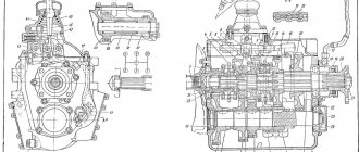
The 5-speed gearbox includes:
- Gearbox housing, in which the primary, secondary and intermediate shafts assembled with gears, as well as synchronizers and bearings are mounted;
- Separate gear block for reverse gears;
- gear shift mechanism in a separate block at the top of the box;
- Gear divider attached to the front end of the gearbox housing 154 KAMAZ.
- Covers with sealing gaskets that cover the shaft bearings, while the outer race of the bearing is centering for the rear bearing cover of the input shaft.
- The outer race of the rear bearing 29 of the driven shaft is centering for the cover 27 of the rear bearing of the driven shaft, which is attached to the rear end of the crankcase of the KPP-154 Kamaz.
- A cuff with a boot installed in the rear part of the cover and having a working edge with a left notch.
- The right wall of the crankcase has a boring in the counters. The axis of the reverse gear block is pressed into this bore, securing it from falling out. The washer itself is screwed with a bolt with a drill, into which a plastic pin is inserted to seal the threaded connection and prevent lubricant leakage.
- On the right side of the crankcase there is a neck for filling oil into the gearbox. It is closed with a plug in which a dipstick is built in to control the level.
- Oil is poured into the gearbox through the neck located on the right wall of the crankcase. The drain plug, screwed into the bosses, is located at the bottom of the crankcase. It is equipped with a magnet that can capture metal particles in the oil.
- There are hatches on both sides of the crankcase for installing power take-offs. The hatches are closed with lids with sealing gaskets. GOST for hatches - 12323.
- Permissible power output of 22064.97 W (30 hp) from each hatch. Power take-off while the vehicle is moving is prohibited.
- The upper right part of the rear wall has a pocket for oil, into which it is thrown by the rotation of the gears. Drilling in the crankcase wall allows oil to pass from the pocket into the cavity of the rear cover of the driven shaft, thus lubricating the worm pair of the speedometer drive.
| 1st Gear | 2nd Gear | 3rd Gear | 4th Gear | 5th Gear | R | |
| P | 7,82 | 4,03 | 2,5 | 1,53 | 1,00 | 7,38 |
| N | 6,38 | 3,29 | 2,04 | 1,25 | 0,815 | 6,02 |
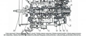
The primary shaft is mounted on 2 ball bearings. The front bearing is located in the crankshaft socket, the rear bearing is located in the bore of the front end of the gearbox housing. The drive shaft is supported by a retaining ring that protects it from shifting.
The input shaft is made together with the gear. The front part of the shaft goes into a cylindrical journal under the front ball bearing and has splines. The hubs of the driven clutch discs are mounted on the splines. The input shaft gear is helical and is constantly engaged with the intermediate shaft drive gear. It consists of an internal ring gear used to connect to the synchronizer carriage ring gear, and an internal cylindrical hole for installing the front roller bearing of the driven shaft.
The intermediate shaft is made together with the crowns of the gears of the 1st and 2nd gears and reverse gear. The 3rd and 4th gears and the intermediate shaft drive gear are pressed onto the front end of the shaft.
The driven shaft assembly with gears and synchronizers is installed coaxially with the drive shaft. A thrust ring with internal splines secures the 3rd and 4th gears. The arrangement of the ring splines is such that they are opposite the shaft splines. The ring is kept from turning by a spring-loaded key. Gear bearings receive oil supplied by the drive shaft oil pump through a drilled channel along the axis of the driven shaft. Inertial type synchronizers (2 pieces) are responsible for shockless gear shifting: 2nd, 3rd, 4th, 5th. The gear shift mechanism is mounted in the top cover of the box and is formed by:
- rods (3 pcs);
- shift forks (3 pcs);
- rod heads (2 pcs);
- clamps (3 pcs);
- fuses for 1st gear and reverse gear;
- rod locks. The rod lock is formed by 2 pairs of balls and a pin. The balls are located between the rods in the bushings, the pin is located in the hole in the middle rod between the balls.
The balls have such diameters that with a given inter-rod distance, if the rod moves from the middle position, they are able to exit the holes of the moving rod and enter the holes of the stationary rods. On the cover of the switching mechanism there is a support for the PP lever. On the right there is a set screw that secures the neutral position of the lever. In the working position, the screw must be turned out. The gear divider itself is formed:
- Spur gears;
- Drive and intermediate shafts;
- Synchronizer and PP mechanism with pneumatic control.
Metal spacers (02, 03 mm) installed between the back cover and the outer race of the ball bearing regulate the axial movement of the drive shaft. The involute splines for the finger synchronizer at the end of the shaft are divided by 2 grooves into 3 crowns. The teeth of the outer rings are thinner than those of the middle one, which makes it possible to create a “lock” to prevent the gears in the divider from switching off themselves. 2 roller bearings are the basis for the drive shaft gear rotating on them. Using an oil injection ring, oil is supplied through inclined drillings of the drive shaft into the internal cavity of the latter, after which it ends up in the channels of the drive and driven shafts of the main gearbox. The gear divider shift mechanism is located on the left side of the divider housing.
Technical specifications
The main parameter for any gearbox is the ratio of gear ratios for each stage. In the case of the KAMAZ 154 gearbox, this parameter is as follows:
- 1 (low) – 7.82;
- 1 (high) – 6.38;
- 2 (low) – 4.03;
- 2 (high) – 3.29;
- 3 (low) – 2.5;
- 3 (high) – 2.04;
- 4 (low) – 1.53;
- 4 (high) – 1.25;
- 5 (low) – 1;
- 5 (high) – 0.815;
- reverse (low) – 7.38;
- reverse (high) – 6.02.
Tapered single-row roller-type bearings are mounted on the transmission shafts. The exception is the front one, pressed onto the drive shaft in the dividing device housing - a ball element is used here. The bearings on which the gears are installed are separator, roller design, double row without rings. The 4th gear gear wheel also has a roller bearing, but there is no cage.
The synchronizer unit is inertial, finger-type. It has conical rings made of brass. Gear transmissions are helical with constant mesh. The exception is the 1st gear and reverse gears.
Lubricating fluid is supplied to parts using a combined method. The gear and divider bearings are lubricated by the oil injection mechanism, and lubricant is sprayed onto the remaining parts. Power is removed from the main part of the KAMAZ 154 gearbox in accordance with GOST 123-23. On the right, the ring gear of the gears located in a separate reverse block is engaged. On the left is the ring gear on the gear wheel of the reverse intermediate shaft.
The transmission is controlled manually. On the main part there is a remote type drive, on the divider there is a pneumomechanical preselector.
How to maintain a gearbox on KamAZ
Maintenance consists of:
- adjusting the gear shift drive;
- adjusting the gap in the divider activation valve;
- as well as periodic oil renewal.
- Adjusting the gap between the end of the cover and the stroke limiter of the splitter valve rod: First, check the adjustment of the clutch release drive; adjustments are made as needed; The valve stem stop nuts, located on the pneumatic booster piston pusher, are unlocked and unscrewed. The control terminal of circuit IV of the auxiliary brake drive of the pneumatic brake drive is connected to a pressure gauge. The pressure in the circuit is brought to 7-7.5 kgf/cm; The clutch pedal is pressed all the way; the stop of the valve rod for switching on the divider is brought into contact with the valve rod limiter and moves towards the valve rod. The resulting gap between the end of the valve cover and the stem stop should be 0.2 - 0.3 mm. In this position, the valve stem stop is secured with nuts and locked with bend washers. If the pressure in the IV circuit of the auxiliary brake system drive has dropped to 6.2 kgf/cm2, the gap can be increased to 0.6 mm. Next, the valve stem and cover are closed with a rubber dust guard;
- Checking the oil. The oil filler plug is turned out, the indicator is wiped with a clean rag and inserted into the filler hole until the plug rests against the thread. No need to twist.
- The oil is changed at least once a year, but only if the car travels less than 90,000 km. If the car is involved in heavy work, then the number of times the oil is changed increases significantly. Therefore, when deciding on a replacement, you need to start not from the manufacturer’s recommendations, but from the operating conditions of a particular car. When replacing, the hot oil is drained through the drain holes (to do this, remove the plugs located in the lower part of the gearbox housings and in the lower part of the gear divider housing). The magnets of the drain plugs are cleaned of dirt and metal particles. The box and divider crankcases are washed with clean oil. Clean oil is poured into the gearbox, which must be cranked in neutral gear for 10 minutes; Then the oil is drained from the gearbox, the drain plugs are screwed in and TSp-1.5K lubricant is poured up to the upper mark of the level indicator. After this, you need to turn the gearbox back to neutral for 3-5 minutes. If after all the manipulations when measuring the level it turns out to be insufficient, then the oil needs to be added. The oil must be hot, because... the higher its temperature, the lower the viscosity.
Maintenance and repair
The most common problem in the gearbox is wear on the gears and bearings. Parts are constantly in motion and wear out due to friction. In such cases, it is impossible to restore or repair the gearbox; the elements are replaced with new ones.
Signs of poor functioning of the gearbox-154:
- spontaneous transmission shutdown;
- increased noise and knocking;
- complex activation of the mechanism;
- locking in one position.
Repairing a box with a divider includes 6 stages:
- Disassembling the mechanism.
- Defect detection.
- Replacement of worn parts or adjustment of parameters.
- Changing transmission oil.
- Assembly.
- Test Drive.
During repair work, regulate:
- the size of the gap between the end of the cover and the stroke limiter of the divider activation valve rod;
- switch travel;
- drive for controlling the switching mechanism.
Remove the gearbox as follows:
- Drain the oil from the crankcase.
- Clean the magnet of the plug.
- Lower the spare tire.
- Disconnect the warning lamp switch wire, ventilation pipes, and muffler mounting brackets.
- Unscrew the flange mounting nuts.
- Loosen the clamp tees.
- Remove the clutch pneumatic booster, then the driveshaft.
- Remove the starter mounting bolts.
- They push the gearbox back, lower it onto a cart and roll it out from under the car.
Transmission repair is performed as follows:
- remove the air switch;
- unscrew the mounting bolts;
- remove the roller;
- unfasten the gear shift fork;
- remove the synchronizer;
- dismantle the shaft and fork of the release device;
- unscrew the fasteners that hold the rear bearing cover on the drive shaft;
- remove the cover, dismantle the rear bearing and shaft;
- unscrew the support roller washer and the bearing cup bolts, remove the parts;
- use a wooden block to knock out the shaft and remove the bearing from the divider housing;
- clamp the splined part of the drive shaft in a vice;
- unscrew the coupling nut and the oil injection nut from the shaft;
- remove the roller bearing, bushing and gears.
Removing the gearbox from the car and installing it
Gearbox removal includes
- The oil is drained from the crankcase;
- This is followed by tilting the cabin and removing the floor panels to gain access to the gearbox;
- Disconnecting the battery from the electrical circuit, disconnecting the terminal connecting the main switch to the frame;
- Disconnecting and pulling out the wire connecting the starter relay to the “+” terminal of the battery;
- The hose that serves as the connection between the engine intake manifold and the air cleaner connecting pipe is removed. To do this, you need to unscrew the nuts and pull out the bolts of the tie clamps;
- Disconnecting the plug connections of the tachometer, speedometer, trailer socket, brake light sensor, reversing lights, pressure drop indicator sensors in the receivers;
- Disconnecting the muffler mounting brackets to the splitter housing;
- Remove the pneumatic booster for the hydraulic clutch;
- The yoke flange of the propeller shaft of the middle axle is disconnected from the flange of the driven shaft of the gearbox by unscrewing the nuts of the fastening bolts, removing the spring washers and removing the bolts;
- The connecting hose of the ejector pipe is removed after loosening the tension bands;
- The air lines are disconnected from the trailer brake control valve with a 2-wire drive;
- Loosening the bolts securing the front supports of the power unit;
- Unscrewing the nuts of the rear engine mount bolts; removal of bolts;
- Unscrewing the bolts of the beam that serves to support the support to the frame;
- Unscrewing the bolts securing the gearbox support support to the transverse beam;
- Hanging the power unit by the gearbox eye bolts;
- Placing wooden stands under the front and rear halves of the 2nd frame cross member and lowering the power unit;
Important! The thickness of the supports should allow the rear support brackets to be 50 mm higher than the cushions.
- Unscrewing the pinch bolt of the front linkage lever of the gearbox control drive;
- Disconnecting the front linkage from the lever, removing the rubber boot, removing the ball and spring from the ball head of the lever tip;
- Disconnecting 3 bolts of the air divider control ducts from the block on the engine side, aligning the starter mounting bolts; Unscrewing the bolts securing the clutch or splitter housing to the engine flywheel housing by installing the chain grips of the lifting device behind the eye bolts on the gearbox;
- Removing the gearbox and installing it on the trolley.
Transmission Installation Plan
Important! Before connecting the gearbox to the engine, place 15 g of lubricant 158 into the cavity of the front bearing of the drive shaft located in the crankshaft bore;
- Lifting the gearbox and installing it in place with preliminary installation of the clutch release clutch, hose for supplying lubricant to the pressure bearing and release springs.
- Screwing in the bolts securing the divider housing to the engine flywheel housing.
- Screwing in the starter mounting bolts;
- Connecting the divider control pipelines to the connecting block.
- Connecting the front linkage to the lever with preliminary insertion of the ball and spring into the ball head of the lever;
- Screwing in the coupling bolt of the front linkage lever of the gear mechanism control drive;
- Regulation of the remote drive for controlling the gear shift mechanism;
- Hanging the power unit by the eye bolts of the gearbox;
- Screwing in the bolts securing the transmission support support to the transverse beam, after which the wooden blocks are removed from under the second transverse frame and the power unit is lowered onto the supports;
- Screwing in the bolts securing the support beam to the frame;
- Inserting bolts into the holes in the rear supports of the power unit, followed by tightening the self-locking nuts;
- Tightening the bolts securing the front supports of the power unit;
- Connecting air lines to the trailer brake control valve with a two-wire drive;
- Putting on the connecting hose of the ejector pipe and securing it with tightening tapes;
- Alignment of the holes in the yoke flange of the propeller shaft of the middle axle with the holes in the flange of the secondary shaft of the gearbox;
- Inserting bolts into holes, putting on spring washers, tightening nuts.
- Installation of a hydraulic clutch pneumatic booster;
- Attaching the muffler mounting bracket to the gearbox housing;
- Connection of plug connectors of a tachometer, tachograph, semi-trailer socket, brake light sensor, reversing lights, pressure drop indicator sensors in receivers;
- Connection of tachometer plug connectors;
- Putting on the hose connecting the engine intake pipe to the air cleaner connecting pipe;
- Putting on the clamps and securing the hose;
- Connecting the wire connecting the starter relay to the “+” terminal of the battery;
- Connecting the ground switch terminal to the vehicle frame (the terminal is located on the battery box);
- Connecting batteries to the vehicle's electrical circuit;
- Reimbursement of floor panels;
- Pouring oil into the gearbox housing;
- Cabin lowering;
- Check and, if necessary, adjust the free play of the clutch pedal.
Complete set of gearbox 154
The 154 KAMAZ gearbox is equipped with a number of elements. The design includes: clutch; a clutch release fork with a shaft with a lever extending from it; shafts (primary, secondary, intermediate); clutch housing; gearbox housing; rod support; gear shift lever with support, block and rod; axle with reverse gear block; flange to which the cardan is attached; divider with input shaft; roller and ball bearings.
There are also secondary elements: gaskets and rings, covers, springs, cuffs.
Maintenance of KamAZ 154 gearbox
The distance that the input shaft can move inside the divider is determined by the size of the gap between the rear cover and the limiter. We present step-by-step instructions for adjusting the gap between the valve stem movement limiter and the end surface of the cover:
- Check whether the drive that disengages the clutch is adjusted correctly; if necessary, make adjustments.
- Loosen the fixing elements and unscrew the nuts on the valve rod stop (the nuts are located on the piston pusher in the pneumatic booster).
- The air brake system has an auxiliary brake.
- There is a control terminal on its drive circuit - a pressure gauge must be connected here.
- Bring the pressure inside the circuit to 7-7.5 kgf/cm2.
- Smoothly and fully depress the clutch.
- Slide the stop towards the valve stem until it touches and move them so that the end of the valve cover and the stop are 0.2 to 0.3 mm apart. Secure the valve stem stop with nuts and install lock washers.
- If the air pressure in the auxiliary brake activation circuit is 6-6.5 kgf/cm2, then the gap should be 0.6 mm.
- The gap should be checked immediately after pressing the clutch pedal.
- Attach the rubber boots to the valve cover and stem.
Checking the lubricant level in the 154 KAMAZ gearbox:
- Unscrew the plug covering the oil filler neck. There is a dipstick on its reverse side.
- Wipe the dipstick with a clean rag and insert it back into the neck so that the plug rests against the thread (no need to wrap it).
- Take out the pointer. Check to what extent the oil trace reaches.
The oil is changed when the unit is warmed up to operating temperature. There are three drain holes - two in the gearbox housing and one in the divider housing. Proceed as follows:
- Unscrew the drain plugs and allow the waste fluid to drain.
- Clean the magnetic elements on the inside of each plug from metal shavings and dirt.
- Screw the plugs into place.
- Fill the gearbox housing with flushing oil (about 12 liters will be needed).
- Set the shift lever to the “neutral” position and turn the engine for 10-15 minutes.
- Drain the flushing fluid.
- Fill in transmission oil TSp-1.5K. Run the engine again for a few minutes, then turn off, wait 2-3 minutes to allow the fluid to drain into the crankcase and check the level. If necessary, top up.
The oil change in the 154 KAMAZ gearbox should be carried out every 90 thousand km or every three years.
Possible faults
All gears are difficult to engage; when engaging first or reverse, a grinding noise is heard.
→ The clutch does not disengage completely - the clutch requires adjustment.
The gear shift lever moves with excessive force.
→ The rods are dirty, the lubricant is thick or missing - clean the supports from dirt and lubricate.
First and reverse gears work flawlessly, and when the others are engaged, a blow is felt and a grinding sound is heard.
→ The cone rings in the synchronizer are worn out - replace the faulty parts.
The cotters in the divider switching drive are worn out.
→ The valve channels and breather are dirty. It is necessary to disassemble, wash the inside and add lubricant to the valve.
→ There is no gap between the traction fork block and the carriage on the synchronizer - adjust the distance between the elements.
The gears disengage themselves while driving.
→ The switching drive is worn out or not adjusted - replace the failed elements, adjust the mechanism.
→ The spline lock on the secondary shaft does not work - replace the shaft together with the synchronizer.
It is impossible to engage gears on the main box.
→ The switching drive is worn out or requires adjustment - replace the necessary components and adjust.
→ Drive shaft gear bearings are crumbling - install new parts.
The gearbox operates with increased noise.
→ Gear teeth are worn out or their bearings are damaged - replace faulty components.
Divider gears cannot be engaged.
→ The pistons in the air distributor have become sour - disassemble, wash, lubricate.
→ The valve that turns on the divider is not adjusted - adjustment is needed.
→ Valve stop is broken - replace.
→ Dirt in the pneumatic system - wash and blow with compressed air the throttle openings, valve system and air channels.
→ The cable attached to the control valve is broken - replace it.
Lubricant is leaking from the transmission.
→ Excessive pressure inside the crankcase - flush and blow out the breather.
→ The cuffs are worn out - replace them.
→ Gaskets are not tight - install new ones.
The clutch does not disengage completely.
→ In the main box, the brass rings on the synchronizers are worn out - replacement is required.
The brass rings on the synchronizers in the divider have failed.
→ The stop of the valve switching on the divider is not adjusted - the position of the stop needs to be adjusted and the synchronizers replaced.
→ The clutch does not disengage completely - inspect the condition of the clutch drive.
Removal and installation
Dismantling:
- Drain the transmission oil.
- Tilt the cab and remove the shields blocking access to the checkpoint.
- Disconnect the wires from the battery. Disconnect the ground.
- Disconnect and remove the wire that goes from the positive terminal of the battery to the starter relay.
- Remove the hose that runs between the inlet and the air cleaner.
- Disconnect the plugs of the instrument panel, brake light sensor, taillight wires, pressure sensors inside the receivers.
- Remove the brackets that secure the muffler to the splitter housing.
- Remove the pneumatic booster of the hydraulic clutch drive.
- Separate the flanges of the cardan and secondary shaft.
- Remove the bolts and bushings, loosen the clamps and remove the hose from the ejector pipe.
- Loosen the bolted connection of the front and rear engine mounts (remove the bolts on the rear).
- Unscrew the support beam from the frame.
- Unscrew the gearbox support from the cross member.
- Hang up the motor.
- Place thick blocks of wood under the second cross member of the frame and lower the engine onto them.
- Unscrew the bolt that tightens the lever element of the front linkage of the control drive and the gearbox.
- Disconnect the rod from the lever. Pull off the boot and remove the ball and spring from the tip.
- Unscrew the bolts that secure the splitter air ducts to the block from the front side.
- Remove the starter.
- Raise the gearbox using a hoist.
- Unscrew the clutch housing and divider.
- Move the gearbox housing back so that the drive shaft comes out of its housing completely.
- Move the box onto the cart using the lifting mechanism.
Installation:
Before you start mating the transmission with the internal combustion engine, apply automotive grease No. 158 to the inside of the bearing on the crankshaft into which the drive shaft is mounted.
- Secure the clutch release clutch, the springs and the hose that supplies oil to the pressure bearing.
- Lift the box using the lifting mechanism and place it on the car.
- Connect the ends of the engine flywheel housings and the divider, tighten with bolts.
- Install the starter.
- Connect the control hoses to the intermediate block.
- Insert the ball with the spring into the spherical part of the lever and attach the front link to it.
- Bolt the traction lever.
- Adjust the remote control drive of the gearbox mechanism.
- Hang the gearbox using eye bolts.
- Bolt the support leg and cross beam together.
- Remove the previously placed wooden blocks from below and lower the unit onto the supports.
- Bolt the beam that supports the supports to the frame.
- Use bolts and nuts to tighten the rear supports.
- Screw in the front support bolts.
- Connect the air hoses to the brake valve of the two-wire drive trailer hitch.
- Throw on and tighten the ejector pipe hose using clamps.
- Align the flanges of the driveshaft leading to the middle axle with the transmission driven shaft.
- Tighten the parts with nuts and bolts.
- Install the pneumatic booster for the hydraulic clutch drive.
- Bolt the bracket that secures the muffler to the gearbox housing.
- Connect to your connectors the wires going to the speedometer, tachometer, trailer socket, brake light sensor, tail lights and pressure sensors in the receivers.
- Connect the connecting pipe of the air cleaner and the engine intake system with a hose.
- Secure the hose with clamps.
- Connect the positive wire of the starter relay to the battery.
- Connect the ground wire to the frame.
- Connect the wires to the battery terminals.
- Place shields on the floor.
- Pour lubricant into the transmission.
- Place the cab upright.
- Check and adjust the free play of the clutch release pedal.
Checking gearbox 154 after installation
To check the 154 gearbox for functionality after repair, you will need a special stand. The gearbox test bench must be equipped with the following devices:
- a mechanism for providing two rotation speed modes to the drive shaft - 1300 rpm and 2600 rpm;
- a clutch connected to the input shaft of the gearbox, which disengages when changing gears. On parts driven by the clutch, the inertial moment should be no more than 12.7 Nm/cm or 1.3 KGS*m/cm2;
- a device that brakes the secondary shaft with a force of 49.1 Nm (in 1st gear and in reverse) and 98-147 Nm (in 2nd-5th gears);
- a tool that measures the torque transmitted to the driven shaft;
- pneumatic divider switch operating with a pressure inside the pneumatic system of 590-680 kPa;
- devices that determine noise levels.
During testing, engine oil heated to operating temperature (80-90 C) is used as a lubricant.
The 154 KAMAZ gearbox is tested in two modes - with and without load.
In unloaded mode, the correctness of gear shifting and the functionality of the divider are diagnosed. After checking, without allowing the lubricant to cool, drain it.
No-load test mode:
- Set the main gearbox shift lever to neutral, switch the divider to the top gear position. Spin the drive shaft to 1300 rpm and let it run in this mode for 1.5-2 minutes.
- The same thing, but the shaft should be spun to 2600 rpm.
- Do not change the speed, leave the main box in the “neutral” mode, and switch the divider alternately to both modes.
- The rotation speed is the same - 2600 rpm. Set the divider to the “highest” mode, switch the main transmission, changing gears sequentially. Start in reverse, then first and up to fifth. Then descending - from fifth to first and reverse.
Checking the 154 KAMAZ gearbox under load:
- Increase the drive shaft speed to 2.6 thousand rpm.
- Load the secondary shaft with a torque of 49 Nm and sequentially engage the gears with both the gearbox and the divider, start with reverse, then the first and in order to the fifth, including higher and lower ones.
- Do the same with a load of 98.1-147 Nm.
The difference between the KAMAZ 154 and 152 gearboxes
The KAMAZ 154 transmission and its predecessor have a common mechanism in common, the switching divider, here it is updated. The first thing that may catch your eye is the upper support of the remote gear shift device. She looks different.
There are several variations of the 154 gearbox. One is regular (154-1700051), the second is sealed (154-1700056). Externally, these modifications can be distinguished by the appearance of the clutch lever. In the first case it is straight, but on a sealed unit it is curved.
Old boxes 152 and 15 are equipped with the same type of divider switch; they are distinguished by tubular connections extending from the divider valve, switching mechanism, and air distribution device. Version 154 does not have this mechanism.
Now let's talk about the differences between the 15th gearbox model and the 152. On the latter, engineers simplified the system that controls the divider. But these are external differences, the most important changes of version 152 are internal:
- Reinforced splines on the divider drive shaft, synchronizer clutch and carriage.
- The gears on the intermediate shaft are fastened with high interference without keys.
- The lock on the splines in the gap between the gearbox driven shaft and the synchronizer carriage has disappeared.
- The diameter of the teeth on the couplings has been increased to prevent self-disengagement of gears.
- The roller bearing of the front support of the driven shaft has been strengthened.
- Extended fourth gear ring.
The main difference between the 15th and 152nd gearboxes is in the depth of the spline grooves and in the synchronizers. Therefore, it is believed that from a newer box you can simply transfer these parts into the outdated 15th. In principle, this is possible, but engineers calculate the parameters of the entire structure completely. Therefore, it makes no sense to cram in any one detail. It is worth replacing spare parts only comprehensively.
Repair of gearbox divider for Kamaz vehicles
Possible breakdowns
- The ball bearings of the primary and secondary shafts are faulty;
- Overdrive gear roller bearings;
- The shaft and gear are damaged by the rollers;
- Gear teeth are broken;
- The fastening bolts of the secondary shaft support washer are loosened;
- To correct problems, the divider must be disassembled, the problem area identified, parts replaced, and the device reassembled.
Disassembly
- Removing the gear shift fork;
- Removing the synchronizer;
- Simultaneous removal of the release bearing fork and shaft;
- Unscrewing and removing the rear bearing cover of the input shaft;
- Removing the input shaft and bearing, after which it is necessary to align the cutout of the drive gear with the teeth of the intermediate shaft;
- Removing the intermediate shaft ball bearing cover. For this purpose there is a specially provided thread in the holes of the cover;
- Removing the bearing support washer and the roller bearing of the secondary shaft;
- Removing the bearing together with the glass;
- Knocking out the shaft from a ball bearing with a wooden block;
- Removing the bearing from the divider housing;
- Next, the input shaft is disassembled. It is disassembled by unscrewing the coupling nut with a left-hand thread, then the oil pressure washer, bearing with sleeve, drive gear and roller bearings are removed;
- If necessary, parts are replaced.
How the transmission works
Its main components are a five-speed gearbox and a two-stage multiplier. When disassembling, the following are disconnected from it:
- drive shaft;
- gear transmission;
- synchronizers;
- coupling;
- driven shaft;
- intermediate shafts;
- crankcases;
- drive unit.
The ability to change gears is retained only if the clutch is in the disengaged position; for this purpose, the valve lever is moved to position B or H.
Control drive components:
- lever support, with the help of which switching is carried out;
- O-rings;
- jet thrust;
- axis;
- lever device;
- vibration isolator.
Selecting transmission oil
TSp-15k
Changing the oil in the gearbox in a timely manner will have a positive effect on the functioning of the vehicle. For Gearbox 154, the following type of fuel is suitable - TSp-15K. Its distinctive feature is the reduction of wear of contacting parts. This substance has an optimal viscosity coefficient and freezing point. It can be used to fuel not only KamAZ trucks, but also tractors. The frequency of replacement is directly related to the operating conditions of the machine.
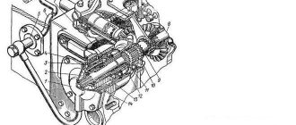
Thus, KamAZ is a freight transport equipped with reliable working mechanisms that are designed for a long functional life. The machine can be equipped with a Model 154 three-way gearbox, the diagram of which shows the general relationship of its constituent elements. They ensure excellent vehicle performance.